EP1521450A2 - Systems and methods for multi-dimensional dither structure creation and application - Google Patents
Systems and methods for multi-dimensional dither structure creation and application Download PDFInfo
- Publication number
- EP1521450A2 EP1521450A2 EP04023230A EP04023230A EP1521450A2 EP 1521450 A2 EP1521450 A2 EP 1521450A2 EP 04023230 A EP04023230 A EP 04023230A EP 04023230 A EP04023230 A EP 04023230A EP 1521450 A2 EP1521450 A2 EP 1521450A2
- Authority
- EP
- European Patent Office
- Prior art keywords
- temporal
- pixel values
- channel
- designated
- pixel
- Prior art date
- Legal status (The legal status is an assumption and is not a legal conclusion. Google has not performed a legal analysis and makes no representation as to the accuracy of the status listed.)
- Withdrawn
Links
Images


Classifications
-
- H—ELECTRICITY
- H04—ELECTRIC COMMUNICATION TECHNIQUE
- H04N—PICTORIAL COMMUNICATION, e.g. TELEVISION
- H04N1/00—Scanning, transmission or reproduction of documents or the like, e.g. facsimile transmission; Details thereof
- H04N1/46—Colour picture communication systems
- H04N1/64—Systems for the transmission or the storage of the colour picture signal; Details therefor, e.g. coding or decoding means therefor
-
- G—PHYSICS
- G09—EDUCATION; CRYPTOGRAPHY; DISPLAY; ADVERTISING; SEALS
- G09G—ARRANGEMENTS OR CIRCUITS FOR CONTROL OF INDICATING DEVICES USING STATIC MEANS TO PRESENT VARIABLE INFORMATION
- G09G3/00—Control arrangements or circuits, of interest only in connection with visual indicators other than cathode-ray tubes
- G09G3/20—Control arrangements or circuits, of interest only in connection with visual indicators other than cathode-ray tubes for presentation of an assembly of a number of characters, e.g. a page, by composing the assembly by combination of individual elements arranged in a matrix no fixed position being assigned to or needed to be assigned to the individual characters or partial characters
- G09G3/2007—Display of intermediate tones
- G09G3/2044—Display of intermediate tones using dithering
- G09G3/2051—Display of intermediate tones using dithering with use of a spatial dither pattern
- G09G3/2055—Display of intermediate tones using dithering with use of a spatial dither pattern the pattern being varied in time
-
- H—ELECTRICITY
- H04—ELECTRIC COMMUNICATION TECHNIQUE
- H04N—PICTORIAL COMMUNICATION, e.g. TELEVISION
- H04N1/00—Scanning, transmission or reproduction of documents or the like, e.g. facsimile transmission; Details thereof
- H04N1/40—Picture signal circuits
- H04N1/40087—Multi-toning, i.e. converting a continuous-tone signal for reproduction with more than two discrete brightnesses or optical densities, e.g. dots of grey and black inks on white paper
Definitions
- Digital images are communicated by values that represent the luminance and chromatic attributes of an image at an array of locations throughout the image. Each value is represented by a given number of bits.
- bandwidth, storage and display requirements are not restrictive, sufficient bits are available that the image can be displayed with virtually uninhibited visual clarity and realistic color reproduction.
- bit-depth is restricted, the gradations between adjacent luminance or color levels can become perceptible and even annoying to a human observer. This effect is apparent in contouring artifacts visible in images with low bit-depth. Contour lines appear in low frequency areas with slowly varying luminance where pixel values are forced to one side or the other of a coarse gradation step.
- contouring artifacts can be "broken up” by adding noise or other dither patterns to the image, generally before quantization or other bit-depth reduction.
- This noise or pattern addition forces a random, pseudo-random or other variation in pixel values that reduces the occurrence and visibility of contours.
- the image is perceived as more natural and pleasing to a human observer.
- Figure 1 illustrates an image display system 1.
- noise or dither patterns 16 can be added to 4 or otherwise combined with an image 2.
- the combined image is then quantized 6 to a lower bit-depth.
- the image may then be displayed directly or , as shown in Figure 1, may be transmitted 8 to a receiver 10.
- the noise/dither 16 that was added to the image may be subtracted 12 or otherwise de-combined with the image to reduce the visible effect of the noise/dither on areas where contouring is not likely to occur.
- the image is then displayed 14 on the receiving end.
- These methods may also be used in systems that do not transmit or receive such as with displays with bit-depth capabilities that are lower than the image data 2 to be displayed.
- an image 2 is combined 28 with a noise/dither pattern 16 and sent to a display system 22 that cannot display the full range of image data contained in the image.
- These display systems 22 may quantize 24 the image data to a bit-depth that matches the display capabilities. The quantized image data is then displayed on the display 26.
- the noise/dither pattern is not subtracted or de-combined from the image. In these systems, less noise can be added to an image before it causes adverse visual impact or "graininess.”
- Various frequency distributions for noise/dither patterns have been found to be more or less visible to the human visual system.
- the human visual system works as a low-pass filter that filters out high frequency data. Therefore, noise concentrated in a high-frequency range is less visible than lower frequency noise.
- a dither/noise pattern that is as big as an image file.
- a smaller dither pattern can be used by repeating the pattern across the image in rows and columns. This process is often referred to as tiling.
- a dither pattern may be repeated from frame to frame as well. Dither patterns may be designed to minimize artifacts created by their repetitive patterns.
- Dither structures may comprise multiple dither patterns to be used across a single image of multiple frames.
- a three-dimensional dither structure as shown in Figure 3, may employ a series of dither patterns. These patterns 30-36 may be arranged in a sequence that is used on sequential frames of video.
- a first dither pattern tile 30 may be used on a first video frame 38 while a next sequential pattern 32 is used on a next successive video frame 40.
- the sequence of patterns 30-36 may be repeated after each pattern in the sequence is used. These sequences may also be specially designed to reduce the occurrence of artifacts from their repetitive temporal patterns.
- Systems and methods of embodiments of the present invention comprise the creation and/or application of dither structures. These structures may be used to reduce the visibility of contouring and other artifacts in still and video images.
- Embodiments of the present invention may be used in conjunction with displays and, in some embodiments, in display algorithms that employ properties of the visual system in their optimization. Some embodiments of the present invention may comprise methods that attempt to prevent the contouring artifacts in displays that have too few gray levels. Some of these displays include LCD or similar displays with a digital bit-depth bottleneck. They may also be used with graphics controller cards with limited video RAM (VRAM). These bit-depth limitations can arise in the LCD display itself, or its internal hardware driver.
- VRAM video RAM
- Some embodiments of the present invention include systems and methods comprising an anti-correlated spatio-temporal dither pattern, which exhibits high-pass characteristics in the spatial and temporal domains.
- Methods for creating these patterns comprise generation of a series of dither tiles for multiple image characteristic channels and the temporal domain.
- a different dither pattern tile 50, 52 & 54 may be generated for each of three RGB color channels and this set of three tiles 58 may be generated for a series of temporal frames 58, 60, 62 & 64.
- a multi-dimensional array of tiles is generated.
- varying numbers of chrominance and luminance channels may be used and varying patterns may be used in successive frames in the temporal domain also.
- a set of dither pattern tiles is generated one element at a time by successively designating or assigning each pixel value according to an anti-correlation or dispersion method, which may be referred to as a merit function.
- a merit function pixel values in the dither pattern tiles can be generated.
- a dispersion-related merit function is used to place each pixel.
- a first pixel 80 is placed in the red channel tile 78 of frame 1. Since this is the first pixel the dispersion merit function may place the pixel value at essentially any location. This dispersion merit function can relate to values in the same color channel or a combination of color channels.
- Each dither pattern tile (i.e., 78) can be completed individually or a set of tiles making up a frame may be generated simultaneously. For example, a pixel may be placed in a red channel tile 78 followed by a pixel placement in a green channel tile 82 of the same frame followed by a pixel placement in the blue channel tile 84 of the same frame. Alternatively, a single color channel tile may be completed before placement of pixel values in another color channel tile of the same frame.
- each frame's dither pattern tiles are generated with reference to the patterns already established in previous frames and currently developing frames.
- the weighting of previous frames may vary. For example, the weight given to pixel values in the closest preceding frame may be higher than that given to the next closest preceding frame
- the number of dither pattern frames is much less than the number of frames in a video clip so a series of pattern frames is reused in sequence.
- This cycle makes the first frame of the sequence 86 immediately follow the last frame 90. Accordingly, if these frames are not correlated, visible artifacts may develop. To avoid this, the last frames in a sequence are generated with reference to the first frame or frames as well as the previous frame or frames. This helps ensure that the pattern is continuously high-pass throughout multiple cycles.
- a 32x32 spatial dither pattern tile is generated for each color channel for RGB application. This pattern is created for 32 temporal frames thereby yielding a 32x32x32x3 array.
- the size is not a factor in the overall function of some embodiments and many different dimensions may be used.
- a merit function is used to disperse the pixel values into a high-pass relationship. This high-pass relationship may exist spatially within a dither pattern tile, spectrally across color channel tiles and temporally across successive frames. In order to achieve all these relationships, the location of a pattern pixel value must have feedback from other pixel values within the tile pattern, other color channel tiles within the frame and pixel values in adjacent frames. Dispersion or anti-correlation across color channels can help reduce fluctuation in luminance where human vision has the highest sensitivity.
- Figure 6 is a diagram showing a mutual high-pass temporal and spatial relationship achieved in some embodiments of the present invention.
- a variety of feedback functions and parameters may be used.
- a level may correspond to a luminance value, such as a gray-scale value in a monochrome image, a value for the luminance channel in image formats with specific luminance channels (i.e., LAB, LUV) and other parameters related to the visual perception of a pixel. This number may vary significantly according to specific application factors.
- the dither values may be evenly distributed among each level.
- the display is not linear so the level distribution may be distributed in a non-linear manner.
- the number of output bits is greater than 4 the non-linear effect is small so uniform distribution does not cause a large non-linear error. Accordingly, the number of pixel values may generally be distributed evenly among levels.
- more threshold values should be distributed in the lower portion of the threshold range to compensate for the non-linear gamma effect.
- Some embodiments of the present invention comprise a spatial/temporal merit function. This function serves to evenly distribute the dither values in the spatial/temporal dither space so that there is minimum fluctuation in both luminance and chrominance when viewed from a certain distance.
- a model of a charged ball in the 3D space of the 3D dither pattern is used.
- the process of assigning a dither value is equivalent to putting a charged ball at the corresponding location in 3D space.
- each ball repels other balls of the same charge as far as possible.
- the new ball (dither value) ends up in the least occupied space.
- we use the inverse-distance-squared function as the repellent function.
- This function is the same as that typically used to model the repellent force between charged particles of same charge.
- the distance can be normalized by the spatial resolution of the display in pixels per inch (PPI) and the temporal frame rate (fps).
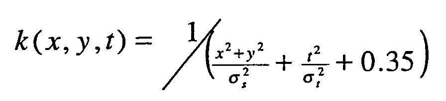
- the repellent function may be implemented with a convolution kernel as where x and y are the spatial coordinates, t is the temporal coordinate.
- the constant 0.35 may be used to prevent division by 0.
- This constant may also be used to adjust cross color channel influence. Other values may also be used for this constant. In these embodiments, a smaller constant will make it less likely that another color dither value will be assigned at this location due to the influence of a cross-color-channel repellent function.
- Sigma (ó s ) defines the spatial extent of the repellent function, which is a function of display resolution (PPI) and viewing distance.
- Sigma (ó t ) defines the temporal extent of the repellent function, which can be a function of the temporal frame rate.
- these parameters may be adjusted so that the power spectrum of the dither pattern is below the power spectrum of the equivalent noise of the human eye.
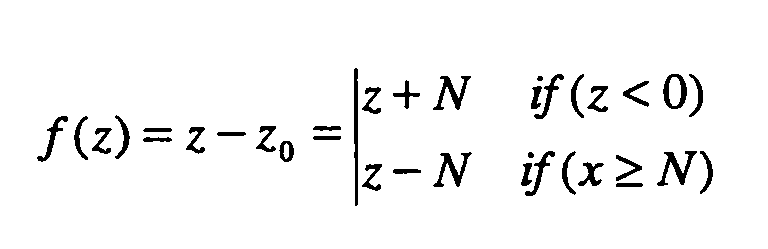
- repellent functions may be updated. Due to the limited size of the dither pattern, the shift operation can cause the kernel to extend beyond the size of the dither pattern.
- the kernel may be wrapped around the dither pattern when the kernel extends beyond the dither pattern, i.e where z can be x, y, or t, and N is the size of pattern in z dimension.
- Figure 7 depicts a typical repellent function of some embodiments of the present invention. The peaks are located at the position of dither values that are already assigned.
- Cross channel repellent function may be implemented using a set of weighted repellent functions. where C ii is the weight of cross color channel repellent function. The apostrophe (') is used to denote the combined repellent function from all the color channels.
- the cross channel weighting function may also be level dependent.
- C1 is the smallest so that the cross channel effect is very small, while at both low level and high level, the cross channel weighting function is larger.
- the algorithm may randomly pick one from the many positions. Once a dither value is assigned, the repellent function may be updated to account for the new pixel value. This process is repeated for all the colors, pixels, levels, and frames, so that every element in the dither pattern is assigned.
- dither pattern parameters are designated 102 to define the characteristics and dimensions of the tile set.
- the steps of these methods may be ordered in many ways, however, in the exemplary embodiments illustrated in Figure 8, each dither pattern frame is designated 104 before proceeding to the next frame. Once a frame has been initialized, these methods proceed to designate each level 106 of the dither pattern frame.
- the cross color-channel-influence is evaluated 108.
- This influence may vary according to the level therefore it is typically calculated inside the level determination loop 106, however, in non-level-dependent embodiments, it may be calculated in another order.
- This cross-color-channel influence may also depend on other parameters in lieu of or in addition to level parameters.
- the spatial and temporal dispersion or repulsion function is then constructed 110.
- a first pixel is then selected and a pixel counter is incremented 112 and a color channel tile is selected 114.
- the effects of the cross-color-channel function and the spatial/temporal repellent function may then be combined 116 to provide a composite function for which maxima and minima may be determined.
- the minimum or maximum values of this combined function are then found 118 to determine the optimal or preferable pixel location. If multiple minima or maxima are found, a single value can be selected randomly or by some other process. Once this location is determined, a pixel value is assigned according to the current level.
- the combined repellent function is then revised to reflect the presence of the newly designated pixel value 120.
- the process then jumps to the next color tile 122 in the frame and proceeds to designate a pixel value for that tile as explained for steps 112 through 120.
- the pixel counter is incremented 124 and another pixel value is designated for each color tile as explained in steps 112 through 122.
- the process jumps to the next level 126 and designates the pixel values for that level. This process continues until all pixels for each level of each color tile are designated.
- the process then advances to the next frame of the dither pattern array 128 and repeats the process until all frames are designated. Once all frames are designated, the process ends 130 and the dither pattern array may be applied to an image.
- a dither pattern created with an embodiment of the present invention has been analyzed using Fourier analysis.
- the spatial/temporal power spectrum of the dither pattern is shown in Figure 8.
- the dither pattern is high pass both spatially and temporally similar to the target spectrum.
- dither pattern pixel values may be designated in other orders.
- the pixel incrementing loop 112 may reside within the color channel selection loop 114 causing all pixels values for one level of a color channel to be designated before proceeding to the next color channel.
- Many other variations in these processes may also be implemented by one skilled in the art based on the information described herein.
- Some embodiments of the present invention may also employ a tile stepping method as illustrated in Figure 9 for further reduction of the possibility of visible artifacts.
- a spatio-temporal array of dither pattern tiles 150 may be used. These dither pattern tiles 150 are typically smaller than the image to which they are applied in order to reduce memory size. The smaller tiles can cover the image in a tile pattern that uses the same tiles repeatedly. In some applications, the same tile is used repeatedly across the image as shown in Figure 3. However, this method can result in visible artifacts caused by the repeated pattern. This problem may be reduced or eliminated by using tiles from multiple successive frames. This method can be employed in the spatial and temporal dimensions.
- tiles can be incremented spatially across an image 152 starting with a first tile frame 160 and then using each successive tile frame 161, 162 & 164 to fill out the tile pattern across the image 152.
- This pattern of successive tile frames can be employed in the temporal direction as well.
- the tile frame succeeding the tile frame used in the prior image frame at any given tile location is used. For example, when a first tile frame 160 is used in the top left position in a first image frame 152, the next successive tile frame 161 is used at that location in the next image frame 154.
- the second tile position in the first frame 152 is occupied by the second tile frame 161 and that position in the second image frame 154 is occupied by the third tile frame 162.
- the same pattern is repeated for each tile position and each image frame. Once the number of tile frames is exhausted, the tile set order is repeated.
- the tile pattern in a particular frame may be varied beyond a sequential spatial order across the rows.
- the tiles may be dispersed in a random spatial order across a frame. Once this random spatial pattern is established in the first frame, the tiles in the next temporal frame and subsequent frames will follow a sequential temporal order such that the tile corresponding to the position of a tile in the first frame will be the next sequential tile in the temporal order established in the dither tile structure.
- a dither tile set 170 is established with tile frames 0 through 3 (172-178) shown in sequential temporal order.
- Tile set 170 will typically comprise many other frames as well, but the quantity illustrated is limited to 4 for simplicity of explanation.
- a first image frame 180 tiles 172-178 and other tiles in a set are dispersed randomly across the frame 180.
- the tile used at any particular location is the next tile in temporal order from the tile used at that location in the previous frame.
- dither tile 6 is used as randomly placed.
- the next tile in temporal order established in the dither tile structure 170, frame 7, is used.
- tile 2 is used and the next tile, tile 3 is used for that location 196 in frame "p+1" 182.
- other non-random and pseudo-random patterns may be employed as well.
Landscapes
- Engineering & Computer Science (AREA)
- General Physics & Mathematics (AREA)
- Multimedia (AREA)
- Signal Processing (AREA)
- Physics & Mathematics (AREA)
- Computer Hardware Design (AREA)
- Theoretical Computer Science (AREA)
- Discrete Mathematics (AREA)
- Liquid Crystal Display Device Control (AREA)
- Control Of Indicators Other Than Cathode Ray Tubes (AREA)
- Facsimile Image Signal Circuits (AREA)
- Processing Of Color Television Signals (AREA)
- Image Processing (AREA)
- Color Image Communication Systems (AREA)
- Controls And Circuits For Display Device (AREA)
- Analogue/Digital Conversion (AREA)
Abstract
Description

Claims (19)
- A method for creating a dither pattern array, said method comprising:a. assigning a value to pixels in the pattern such that subsequent pixel values are placed at a location that is dispersed from previously-placed pixel values that are located in other color channels and other temporal frames.
- A method according to claim 1 wherein said dispersion from pixel values in said other color channels is weighted differently from dispersion from said pixel values in said other temporal frames.
- A method according to claim 1 wherein said dispersion from pixel values in other color channels is weighted such that dispersion from pixel values in a first color channel is weighted differently from dispersion from pixel values in a second color channel.
- A method for creating a dither pattern for a multiple image description channel image, said method comprising:assigning a value to pixels in a plurality of dither pattern tiles (50, 52, 54), each of said tiles being allocated to an image description channel, wherein said assigning is performed using cross-channel influence, such that subsequently-assigned pixel values are placed at a location that is related to the location of previously-assigned pixel values in the same image description channel and related to the location of previously-assigned pixel values in other image description channels.
- A method according to claim 4 wherein said "related to the location" comprises dispersion from the location.
- A method according to claim 4 wherein said "related to the location" comprises dispersion from the location using a combined repellent function comprising a spatial/temporal function and a cross-color-channel function.
- A method according to claim 4 wherein said relation to the location of previously-designated pixels is channel specific such that pixel values in one color channel will disperse differently than pixel values in another channel.
- A method according to claim 4 wherein said relation to the location of previously-designated pixels is channel specific such that pixel values in color channels other than the channel of the pixel being designated will disperse differently than pixel values in the same channel.
- A method according to claim 4 wherein said image description channels are color channels (78, 82, 84).
- A method according to claim 4 wherein said image description channels comprise three channels for each of a red (78), green (82) and blue (84) color.
- A method according to claim 4 wherein pixel values in said channels are assigned in a sequence one channel at a time with cross-channel influence being used to assign pixel locations after a first channel is designated.
- A method according to claim 4 wherein pixel values in said channels are assigned in parallel with cross-channel dispersion influence for each channel.
- A method for creating a spatio-temporal array of dither patterns, said method comprising:a. establishing a spatio-temporal array of dither pattern tiles (50, 52, 54) comprising a plurality of temporal framesets, each of said framesets comprising a plurality of pattern tiles for each of a plurality of color channels (78, 82, 84); andb. designating pixel values in said dither pattern tiles (50, 52, 54) wherein subsequently-designated pixel values are spatially dispersed from previously-designated pixel values in the same dither pattern tile (50, 52, 54), previously designated pixel values in dither pattern tiles (50, 52, 54) in other color channels and dither pattern tiles (50, 52, 54) in other temporal frames.
- A method according to claim 13 wherein said dispersion from pixel values in other temporal frames is weighted wherein temporal frames more temporally distant from a pixel value have a lower dispersion than closer temporal frames.
- A method according to claim 13 wherein said dispersion from pixel values in other color channels is weighted wherein other color channels have a lower dispersion than the color channel in which a pixel value is designated.
- A method according to claim 13 wherein pixel values designated in a last temporal frame are considered temporally adjacent to a first-designated frame wherein said pixel values in said first-designated frame have a dispersion effect on pixels designated in said last frame.
- A method for creating a spatio-temporal array of dither patterns, said method comprising:a. establishing a first temporal frameset comprising dither pattern tiles (50, 52, 54) for each of a plurality of color channels (78, 82, 84);b. selecting a first pixel value level for subsequent pixel value designation;c. calculating a cross-color-channel influence;d. constructing a spatial/temporal repellent function;e. establish a pixel quantity;f. select a color channel (78, 82, 84) for pixel value designation;g. create a combined cross-color-channel and spatial/temporal repellent function;h. find the location of an extreme value of said combined function;i. designate a pixel value corresponding to said first pixel value level at said location;j. update said combined function to account for the presence of said newly designated pixel value;k. select a new color channel;l. repeat steps h through k until a pixel value has been designated in all color channels (78, 82, 84);m. increment a pixel counter value;n. repeat steps h through m until said pixel counter value equals said pixel quantity;o. select a new pixel value level;p. repeat steps c through o until all levels have been designated;q. advance to the next temporal frame;r. repeat steps b through q until all temporal frames have been designated;s. designating a second pixel value at a second point in said second dither pattern tile of said subsequent temporal frameset, wherein said second point is placed at a location that is dispersed away from at least one pixel value in said subsequent temporal frameset, at least one pixel value in a prior temporal frameset;t. repeating step o until all pixel values in said second dither pattern tile have been designated;u. repeating steps n, o & p until all pixels in all dither pattern tiles (50, 52, 54) in said subsequent temporal frameset have been designated; andv. repeating steps j-q for a plurality of framesets.
- A system for creating a spatio-temporal array of dither patterns, said method comprising:a. a spatio-temporal array of dither pattern tiles (50, 52, 54) comprising a plurality of temporal framesets, each of said framesets comprising a plurality of pattern tiles for each of a plurality of color channels (78, 82, 84); andb. a designator for designating pixel values in said dither pattern tiles wherein subsequently-designated pixel values are spatially dispersed from previously-designated pixel values in the same dither pattern tile and dither pattern tiles in other color channels.
- A set of executable instructions for creating a spatio-temporal array of dither patterns, said method comprising:a. establishing a spatio-temporal array of dither pattern tiles (50, 52, 54) comprising a plurality of temporal framesets, each of said framesets comprising a plurality of pattern tiles for each of a plurality of color channels (78, 82, 84); andb. designating pixel values in said dither pattern tiles (50, 52, 54) wherein subsequently-designated pixel values are spatially dispersed from previously-designated pixel values in the same dither pattern tile and dither pattern tiles in other color channels.
Applications Claiming Priority (2)
| Application Number | Priority Date | Filing Date | Title |
|---|---|---|---|
| US676891 | 1984-11-30 | ||
| US10/676,891 US7352373B2 (en) | 2003-09-30 | 2003-09-30 | Systems and methods for multi-dimensional dither structure creation and application |
Publications (2)
| Publication Number | Publication Date |
|---|---|
| EP1521450A2 true EP1521450A2 (en) | 2005-04-06 |
| EP1521450A3 EP1521450A3 (en) | 2006-12-27 |
Family
ID=34314041
Family Applications (1)
| Application Number | Title | Priority Date | Filing Date |
|---|---|---|---|
| EP04023230A Withdrawn EP1521450A3 (en) | 2003-09-30 | 2004-09-29 | Systems and methods for multi-dimensional dither structure creation and application |
Country Status (3)
| Country | Link |
|---|---|
| US (1) | US7352373B2 (en) |
| EP (1) | EP1521450A3 (en) |
| JP (1) | JP4703152B2 (en) |
Families Citing this family (20)
| Publication number | Priority date | Publication date | Assignee | Title |
|---|---|---|---|---|
| US8243093B2 (en) | 2003-08-22 | 2012-08-14 | Sharp Laboratories Of America, Inc. | Systems and methods for dither structure creation and application for reducing the visibility of contouring artifacts in still and video images |
| US7352373B2 (en) * | 2003-09-30 | 2008-04-01 | Sharp Laboratories Of America, Inc. | Systems and methods for multi-dimensional dither structure creation and application |
| KR20050055459A (en) * | 2003-12-08 | 2005-06-13 | 엘지전자 주식회사 | Method and apparatus of driving plasma display panel |
| US20080158428A1 (en) * | 2007-01-03 | 2008-07-03 | Tvia, Inc. | Dynamic Cross Color Elimination |
| US9024966B2 (en) * | 2007-09-07 | 2015-05-05 | Qualcomm Incorporated | Video blending using time-averaged color keys |
| US8155434B2 (en) * | 2007-10-30 | 2012-04-10 | Sharp Laboratories Of America, Inc. | Methods and systems for image enhancement |
| JP2010049014A (en) * | 2008-08-21 | 2010-03-04 | Sony Corp | Liquid crystal display device |
| IL202028A (en) | 2009-11-10 | 2016-06-30 | Icts Holding Company Ltd | Product, apparatus and methods for computerized authentication of electronic documents |
| US9093031B2 (en) * | 2010-05-28 | 2015-07-28 | Sharp Laboratories Of America, Inc. | Off axis halo mitigation using spatiotemporal dither patterns, each indexed and arranged according to index patterns with diagonal lines of constant index |
| US20120154428A1 (en) | 2010-12-16 | 2012-06-21 | Apple Inc. | Spatio-temporal color luminance dithering techniques |
| WO2012150601A1 (en) * | 2011-05-05 | 2012-11-08 | Au10Tix Limited | Apparatus and methods for authenticated and automated digital certificate production |
| US10116919B2 (en) * | 2012-11-14 | 2018-10-30 | Thomson Licensing | Method and arrangement for estimating at least one cross-channel colour mapping model from an set of tuples of corresponding colours relative to at least two images |
| US9105226B2 (en) * | 2013-01-20 | 2015-08-11 | Qualcomm Incorporated | Spatio-temporal error diffusion for imaging devices |
| TWI546798B (en) | 2013-04-29 | 2016-08-21 | 杜比實驗室特許公司 | Method for dithering images using a processor and computer readable storage medium |
| JP6531471B2 (en) * | 2014-07-29 | 2019-06-19 | 株式会社リコー | Image forming apparatus, dither pattern generating apparatus, and dither pattern generating method |
| US10403192B2 (en) | 2016-09-22 | 2019-09-03 | Apple Inc. | Dithering techniques for electronic displays |
| JP7006519B2 (en) * | 2018-06-14 | 2022-01-24 | 株式会社Jvcケンウッド | Video signal processing device, dither pattern generation method, and dither pattern generation program |
| JP7063214B2 (en) * | 2018-09-25 | 2022-05-09 | 株式会社Jvcケンウッド | Video signal processing device, dither pattern generation method, and dither pattern generation program |
| JP7063213B2 (en) * | 2018-09-25 | 2022-05-09 | 株式会社Jvcケンウッド | Video signal processing device, dither pattern generation method, and dither pattern generation program |
| US11790815B1 (en) * | 2022-08-03 | 2023-10-17 | Innolux Corporation | Display device capable of decrypting visual secret information |
Citations (3)
| Publication number | Priority date | Publication date | Assignee | Title |
|---|---|---|---|---|
| EP1262942A1 (en) | 2001-06-01 | 2002-12-04 | Deutsche Thomson-Brandt Gmbh | Method and apparatus for processing video data for a display device |
| EP1262943A2 (en) | 2001-05-30 | 2002-12-04 | Pioneer Corporation | Display device and display panel driving method |
| US20030164961A1 (en) | 1999-10-22 | 2003-09-04 | Sharp Laboratories Of America, Inc. | Bit-depth extension with models of equivalent input visual noise |
Family Cites Families (80)
| Publication number | Priority date | Publication date | Assignee | Title |
|---|---|---|---|---|
| US3244808A (en) * | 1962-01-12 | 1966-04-05 | Massachusetts Inst Technology | Pulse code modulation with few amplitude steps |
| GB1218015A (en) * | 1967-03-13 | 1971-01-06 | Nat Res Dev | Improvements in or relating to systems for transmitting television signals |
| US3739082A (en) * | 1972-02-29 | 1973-06-12 | Us Army | Ordered dither system |
| US3961134A (en) * | 1975-05-09 | 1976-06-01 | Bell Telephone Laboratories, Incorporated | Bi-level display system |
| US4652905A (en) * | 1978-04-19 | 1987-03-24 | Quanticon Inc. | Instantaneous neutral colors in dither-quantized color television |
| US4568966A (en) * | 1978-04-19 | 1986-02-04 | Quanticon Inc. | Compatible color television with regenerable signals |
| US4275411A (en) * | 1978-04-19 | 1981-06-23 | Bernard Lippel | Dither-quantized signalling for color television |
| US4460924A (en) * | 1978-04-19 | 1984-07-17 | Quanticon Inc. | Dither quantized signalling for color television |
| US5652624A (en) * | 1985-09-23 | 1997-07-29 | Lippel; Bernard | Systems for dither-quantizing and reconstruction of digital television signals |
| US5253045A (en) * | 1985-09-23 | 1993-10-12 | Quanticon Inc. | Interpolating finer intensity levels in dither-quantized television pictures |
| US5148273A (en) * | 1985-09-23 | 1992-09-15 | Quanticon Inc. | Television systems transmitting dither-quantized signals |
| US4758893A (en) * | 1985-09-23 | 1988-07-19 | Quanticon Inc. | Cinematic dithering for television systems |
| US4675532A (en) * | 1985-11-06 | 1987-06-23 | Irvine Sensors Corporation | Combined staring and scanning photodetector sensing system having both temporal and spatial filtering |
| US5059963A (en) * | 1988-01-12 | 1991-10-22 | Sharp Kabushiki Kaisha | Two-level display device with hatching control means |
| US4956638A (en) * | 1988-09-16 | 1990-09-11 | International Business Machines Corporation | Display using ordered dither |
| US5254982A (en) * | 1989-01-13 | 1993-10-19 | International Business Machines Corporation | Error propagated image halftoning with time-varying phase shift |
| US5185602A (en) * | 1989-04-10 | 1993-02-09 | Cirrus Logic, Inc. | Method and apparatus for producing perception of high quality grayscale shading on digitally commanded displays |
| US5164717A (en) * | 1989-09-28 | 1992-11-17 | Sun Microsystems, Inc. | Method and apparatus for the dithering of antialiased vectors |
| US5201030A (en) * | 1989-09-28 | 1993-04-06 | Sun Microsystems, Inc. | Method and apparatus for dithering graphic images |
| US5138303A (en) * | 1989-10-31 | 1992-08-11 | Microsoft Corporation | Method and apparatus for displaying color on a computer output device using dithering techniques |
| US4965668A (en) * | 1989-11-09 | 1990-10-23 | The Grass Valley Group, Inc. | Adaptive rounder for video signals |
| US5218649A (en) * | 1990-05-04 | 1993-06-08 | U S West Advanced Technologies, Inc. | Image enhancement system |
| JP3137367B2 (en) * | 1990-08-09 | 2001-02-19 | 株式会社東芝 | Color panel display control system and computer system |
| JPH04100487A (en) * | 1990-08-20 | 1992-04-02 | Ikegami Tsushinki Co Ltd | Contour correction method |
| US5111310A (en) * | 1990-12-04 | 1992-05-05 | Research Technologies Corporation, Inc. | Method and apparatus for halftone rendering of a gray scale image using a blue noise mask |
| US5714974A (en) * | 1992-02-14 | 1998-02-03 | Industrial Technology Research Laboratories | Dithering method and circuit using dithering matrix rotation |
| US5633958A (en) * | 1992-07-31 | 1997-05-27 | Advantest Corp. | Basic cell for firing spatio-temporal pulses and pattern recognition unit using the same |
| US5333260A (en) * | 1992-10-15 | 1994-07-26 | Digital Equipment Corporation | Imaging system with multilevel dithering using bit shifter |
| US5333262A (en) * | 1992-10-15 | 1994-07-26 | Ulichney Robert A | Imaging system with multilevel dithering using two memories |
| US5469515A (en) * | 1993-05-03 | 1995-11-21 | Lin; Qian | Halftone image formation using dither matrix generated based upon printed symbol models |
| JP3381339B2 (en) * | 1993-10-25 | 2003-02-24 | 株式会社富士通ゼネラル | Error diffusion circuit for pseudo halftone display |
| EP0652671A3 (en) * | 1993-11-05 | 1995-06-21 | Ibm | Mapping colour digital image. |
| IT1262681B (en) * | 1993-11-08 | 1996-07-04 | Cms Spa | MACHINE FOR THE COLLECTION OF USED GLASSES |
| US5473384A (en) * | 1993-12-16 | 1995-12-05 | At&T Corp. | Method of and system for enhancing distorted graphical information |
| JPH0836371A (en) * | 1994-07-22 | 1996-02-06 | Toshiba Corp | Display controller |
| US5619228A (en) * | 1994-07-25 | 1997-04-08 | Texas Instruments Incorporated | Method for reducing temporal artifacts in digital video systems |
| US5696601A (en) * | 1994-08-03 | 1997-12-09 | Xerox Corporation | System and method for redistributing error values from an error diffusion process |
| US6147671A (en) * | 1994-09-13 | 2000-11-14 | Intel Corporation | Temporally dissolved dithering |
| US5623281A (en) * | 1994-09-30 | 1997-04-22 | Texas Instruments Incorporated | Error diffusion filter for DMD display |
| US5726718A (en) * | 1994-09-30 | 1998-03-10 | Texas Instruments Incorporated | Error diffusion filter for DMD display |
| US5712657A (en) * | 1995-03-28 | 1998-01-27 | Cirrus Logic, Inc. | Method and apparatus for adaptive dithering |
| CA2184129A1 (en) * | 1995-08-31 | 1997-03-01 | Donald B. Doherty | Bit-splitting for pulse width modulated spatial light modulator |
| CA2187044C (en) * | 1995-10-06 | 2003-07-01 | Vishal Markandey | Method to reduce perceptual contouring in display systems |
| US6040876A (en) * | 1995-10-13 | 2000-03-21 | Texas Instruments Incorporated | Low intensity contouring and color shift reduction using dither |
| US6052491A (en) * | 1996-01-26 | 2000-04-18 | Texas Instruments Incorporated | Non-monotonic contour diffusion and algorithm |
| JP3492083B2 (en) * | 1996-05-17 | 2004-02-03 | キヤノン株式会社 | Image display device |
| US5822451A (en) * | 1996-06-05 | 1998-10-13 | Eastman Kodak Company | Method for halftoning a multi-channel digital color image |
| US5809178A (en) * | 1996-06-11 | 1998-09-15 | Apple Computer, Inc. | Elimination of visible quantizing artifacts in a digital image utilizing a critical noise/quantizing factor |
| US6795085B1 (en) * | 1997-03-14 | 2004-09-21 | Texas Instruments Incorporated | Contouring reduction in SLM-based display |
| US6028608A (en) * | 1997-05-09 | 2000-02-22 | Jenkins; Barry | System and method of perception-based image generation and encoding |
| US6281942B1 (en) * | 1997-08-11 | 2001-08-28 | Microsoft Corporation | Spatial and temporal filtering mechanism for digital motion video signals |
| GB2336963A (en) * | 1998-05-02 | 1999-11-03 | Sharp Kk | Controller for three dimensional display and method of reducing crosstalk |
| JP4016493B2 (en) * | 1998-08-05 | 2007-12-05 | 三菱電機株式会社 | Display device and multi-gradation circuit thereof |
| US6288698B1 (en) * | 1998-10-07 | 2001-09-11 | S3 Graphics Co., Ltd. | Apparatus and method for gray-scale and brightness display control |
| IT1313382B1 (en) * | 1999-03-18 | 2002-07-23 | St Microelectronics Srl | ESTIMATE OF THE RECURRENT MOTION TEMPORAL SPACE WITH 1/2 MACROBLOCK AND 1/4 PIXEL SUB-SAMPLING |
| US6859275B2 (en) * | 1999-04-09 | 2005-02-22 | Plain Sight Systems, Inc. | System and method for encoded spatio-spectral information processing |
| US6697109B1 (en) * | 1999-05-06 | 2004-02-24 | Sharp Laboratories Of America, Inc. | Method and system for field sequential color image capture |
| KR20020027548A (en) * | 2000-06-15 | 2002-04-13 | 요트.게.아. 롤페즈 | Noise filtering an image sequence |
| WO2002008948A2 (en) * | 2000-07-24 | 2002-01-31 | Vivcom, Inc. | System and method for indexing, searching, identifying, and editing portions of electronic multimedia files |
| GB0026846D0 (en) * | 2000-11-03 | 2000-12-20 | Clayton John C | Motion compensation of images |
| US6501567B2 (en) * | 2000-12-15 | 2002-12-31 | Xerox Corporation | Method and system for designing spatially-partitioned and correlated stochastic screens for color halftoning |
| FR2821217B1 (en) * | 2001-02-21 | 2003-04-25 | France Telecom | METHOD AND SYSTEM FOR ITERATIVE CODING-DECODING OF DIGITAL DATA STREAMS ENCODED BY SPATIO-TEMPORAL COMBINATIONS, IN MULTIPLE TRANSMISSION AND RECEPTION |
| US7221381B2 (en) * | 2001-05-09 | 2007-05-22 | Clairvoyante, Inc | Methods and systems for sub-pixel rendering with gamma adjustment |
| US6892193B2 (en) * | 2001-05-10 | 2005-05-10 | International Business Machines Corporation | Method and apparatus for inducing classifiers for multimedia based on unified representation of features reflecting disparate modalities |
| US6993535B2 (en) * | 2001-06-18 | 2006-01-31 | International Business Machines Corporation | Business method and apparatus for employing induced multimedia classifiers based on unified representation of features reflecting disparate modalities |
| US6950211B2 (en) * | 2001-07-05 | 2005-09-27 | Corel Corporation | Fine moire correction in images |
| US20030062422A1 (en) * | 2001-09-10 | 2003-04-03 | Fateley William G. | System and method for encoded spatio-spectral information processing |
| US7124075B2 (en) * | 2001-10-26 | 2006-10-17 | Dmitry Edward Terez | Methods and apparatus for pitch determination |
| US7098927B2 (en) * | 2002-02-01 | 2006-08-29 | Sharp Laboratories Of America, Inc | Methods and systems for adaptive dither structures |
| JP4420607B2 (en) * | 2002-02-01 | 2010-02-24 | シャープ株式会社 | Image processing method and image processing apparatus |
| US7672369B2 (en) * | 2002-02-13 | 2010-03-02 | Reify Corporation | Method and apparatus for acquisition, compression, and characterization of spatiotemporal signals |
| US7167574B2 (en) * | 2002-03-14 | 2007-01-23 | Seiko Epson Corporation | Method and apparatus for content-based image copy detection |
| DE60323625D1 (en) * | 2002-05-03 | 2008-10-30 | Vialogy Llc | METHOD FOR CHARACTERIZING THE OUTPUT SIGNALS OF A MICROARRAY |
| US7268790B1 (en) * | 2002-08-29 | 2007-09-11 | National Semiconductor Corporation | Display system with framestore and stochastic dithering |
| US7408986B2 (en) * | 2003-06-13 | 2008-08-05 | Microsoft Corporation | Increasing motion smoothness using frame interpolation with motion analysis |
| US7558320B2 (en) * | 2003-06-13 | 2009-07-07 | Microsoft Corporation | Quality control in frame interpolation with motion analysis |
| US7190380B2 (en) * | 2003-09-26 | 2007-03-13 | Hewlett-Packard Development Company, L.P. | Generating and displaying spatially offset sub-frames |
| US8243093B2 (en) * | 2003-08-22 | 2012-08-14 | Sharp Laboratories Of America, Inc. | Systems and methods for dither structure creation and application for reducing the visibility of contouring artifacts in still and video images |
| US7352373B2 (en) * | 2003-09-30 | 2008-04-01 | Sharp Laboratories Of America, Inc. | Systems and methods for multi-dimensional dither structure creation and application |
| JP2006229264A (en) * | 2004-02-09 | 2006-08-31 | Sharp Corp | Method and system for adaptive dither structure |
-
2003
- 2003-09-30 US US10/676,891 patent/US7352373B2/en not_active Expired - Fee Related
-
2004
- 2004-09-27 JP JP2004279297A patent/JP4703152B2/en not_active Expired - Fee Related
- 2004-09-29 EP EP04023230A patent/EP1521450A3/en not_active Withdrawn
Patent Citations (3)
| Publication number | Priority date | Publication date | Assignee | Title |
|---|---|---|---|---|
| US20030164961A1 (en) | 1999-10-22 | 2003-09-04 | Sharp Laboratories Of America, Inc. | Bit-depth extension with models of equivalent input visual noise |
| EP1262943A2 (en) | 2001-05-30 | 2002-12-04 | Pioneer Corporation | Display device and display panel driving method |
| EP1262942A1 (en) | 2001-06-01 | 2002-12-04 | Deutsche Thomson-Brandt Gmbh | Method and apparatus for processing video data for a display device |
Also Published As
| Publication number | Publication date |
|---|---|
| US20050068463A1 (en) | 2005-03-31 |
| US7352373B2 (en) | 2008-04-01 |
| JP4703152B2 (en) | 2011-06-15 |
| JP2005107532A (en) | 2005-04-21 |
| EP1521450A3 (en) | 2006-12-27 |
Similar Documents
| Publication | Publication Date | Title |
|---|---|---|
| US8451289B2 (en) | Systems and methods for dither structure creation and application | |
| US7352373B2 (en) | Systems and methods for multi-dimensional dither structure creation and application | |
| US7692665B2 (en) | Methods and systems for adaptive dither pattern application | |
| US6714206B1 (en) | Method and system for spatial-temporal dithering for displays with overlapping pixels | |
| KR101427607B1 (en) | Multi-color conversion | |
| KR100548841B1 (en) | Display system and bit-depth expansion method of display system | |
| US5734369A (en) | Method and apparatus for dithering images in a digital display system | |
| EP0994457B1 (en) | Apparatus and method of gray scale video signal processing for matrix display apparatus | |
| EP0945847A1 (en) | Frame rate modulation for liquid crystal display (LCD) | |
| EP0606992B1 (en) | Dithering optimization techniques | |
| JP2010040050A (en) | Apparatus and method for sending image data | |
| EP1271927A2 (en) | Method for halftoning a multi-channel digital color image having at least one group of similar color channels | |
| EP0982932A2 (en) | Apparatus and method of performing dithering in a simplex in color space | |
| KR100782821B1 (en) | Methods and systems for video processing using super dithering | |
| WO2009149552A1 (en) | Method and module for improving image fidelity | |
| JP2003116018A (en) | Image processing apparatus and image processing method | |
| US7834887B2 (en) | Methods and systems for combining luminance preserving quantization and halftoning | |
| EP1271923A2 (en) | Digital image multitoning method | |
| KR20050093819A (en) | Method and device for processing video data for display on a display device | |
| EP0606994B1 (en) | Noise quenching method and apparatus for a colour display system | |
| JP2007058213A (en) | Video data processing method and apparatus | |
| Daly et al. | Bit‐depth extension: Overcoming LCD‐driver limitations by using models of the equivalent input noise of the visual system | |
| US20040104918A1 (en) | Three dimensional stochastic screen for LCD and video | |
| JP2006229264A (en) | Method and system for adaptive dither structure | |
| AU671874B2 (en) | Dithering optimization techniques |
Legal Events
| Date | Code | Title | Description |
|---|---|---|---|
| PUAI | Public reference made under article 153(3) epc to a published international application that has entered the european phase |
Free format text: ORIGINAL CODE: 0009012 |
|
| AK | Designated contracting states |
Kind code of ref document: A2 Designated state(s): AT BE BG CH CY CZ DE DK EE ES FI FR GB GR HU IE IT LI LU MC NL PL PT RO SE SI SK TR |
|
| AX | Request for extension of the european patent |
Extension state: AL HR LT LV MK |
|
| PUAL | Search report despatched |
Free format text: ORIGINAL CODE: 0009013 |
|
| AK | Designated contracting states |
Kind code of ref document: A3 Designated state(s): AT BE BG CH CY CZ DE DK EE ES FI FR GB GR HU IE IT LI LU MC NL PL PT RO SE SI SK TR |
|
| AX | Request for extension of the european patent |
Extension state: AL HR LT LV MK |
|
| 17P | Request for examination filed |
Effective date: 20070601 |
|
| AKX | Designation fees paid |
Designated state(s): DE FR GB |
|
| 17Q | First examination report despatched |
Effective date: 20080714 |
|
| RTI1 | Title (correction) |
Free format text: SYSTEMS AND METHODS FOR MULTI-DIMENSIONAL DITHER STRUCTURE CREATION |
|
| STAA | Information on the status of an ep patent application or granted ep patent |
Free format text: STATUS: EXAMINATION IS IN PROGRESS |
|
| STAA | Information on the status of an ep patent application or granted ep patent |
Free format text: STATUS: THE APPLICATION IS DEEMED TO BE WITHDRAWN |
|
| 18D | Application deemed to be withdrawn |
Effective date: 20170401 |