EP1521389A2 - Verfahren und Vorrichtungen zum Abbilden von Daten auf Subträger eines Mehrträgersystems bzw. zum Rückabbilden - Google Patents
Verfahren und Vorrichtungen zum Abbilden von Daten auf Subträger eines Mehrträgersystems bzw. zum Rückabbilden Download PDFInfo
- Publication number
- EP1521389A2 EP1521389A2 EP04104205A EP04104205A EP1521389A2 EP 1521389 A2 EP1521389 A2 EP 1521389A2 EP 04104205 A EP04104205 A EP 04104205A EP 04104205 A EP04104205 A EP 04104205A EP 1521389 A2 EP1521389 A2 EP 1521389A2
- Authority
- EP
- European Patent Office
- Prior art keywords
- data
- subcarriers
- station
- assigned
- serial
- Prior art date
- Legal status (The legal status is an assumption and is not a legal conclusion. Google has not performed a legal analysis and makes no representation as to the accuracy of the status listed.)
- Withdrawn
Links
- 238000000034 method Methods 0.000 title claims description 45
- 238000013507 mapping Methods 0.000 title claims description 17
- 239000000969 carrier Substances 0.000 claims abstract description 7
- 238000006243 chemical reaction Methods 0.000 claims description 28
- 230000009466 transformation Effects 0.000 claims description 15
- 238000004891 communication Methods 0.000 claims description 14
- 230000005540 biological transmission Effects 0.000 description 11
- 238000013459 approach Methods 0.000 description 7
- 239000008186 active pharmaceutical agent Substances 0.000 description 5
- 230000008569 process Effects 0.000 description 5
- 238000012545 processing Methods 0.000 description 4
- 230000008901 benefit Effects 0.000 description 3
- 230000006870 function Effects 0.000 description 3
- 238000004364 calculation method Methods 0.000 description 2
- 238000005516 engineering process Methods 0.000 description 2
- 230000006872 improvement Effects 0.000 description 2
- 230000009467 reduction Effects 0.000 description 2
- 238000012546 transfer Methods 0.000 description 2
- 230000010267 cellular communication Effects 0.000 description 1
- 238000010276 construction Methods 0.000 description 1
- 238000000354 decomposition reaction Methods 0.000 description 1
- 230000001419 dependent effect Effects 0.000 description 1
- 238000012938 design process Methods 0.000 description 1
- 238000001514 detection method Methods 0.000 description 1
- 238000005265 energy consumption Methods 0.000 description 1
- 238000001914 filtration Methods 0.000 description 1
- 238000009432 framing Methods 0.000 description 1
- 238000003384 imaging method Methods 0.000 description 1
- 230000001771 impaired effect Effects 0.000 description 1
- 238000010295 mobile communication Methods 0.000 description 1
- 238000005070 sampling Methods 0.000 description 1
- 238000000926 separation method Methods 0.000 description 1
- 238000001228 spectrum Methods 0.000 description 1
- 238000009827 uniform distribution Methods 0.000 description 1
- 239000002699 waste material Substances 0.000 description 1
Images


Classifications
-
- H—ELECTRICITY
- H04—ELECTRIC COMMUNICATION TECHNIQUE
- H04L—TRANSMISSION OF DIGITAL INFORMATION, e.g. TELEGRAPHIC COMMUNICATION
- H04L5/00—Arrangements affording multiple use of the transmission path
- H04L5/02—Channels characterised by the type of signal
- H04L5/023—Multiplexing of multicarrier modulation signals, e.g. multi-user orthogonal frequency division multiple access [OFDMA]
-
- H—ELECTRICITY
- H04—ELECTRIC COMMUNICATION TECHNIQUE
- H04L—TRANSMISSION OF DIGITAL INFORMATION, e.g. TELEGRAPHIC COMMUNICATION
- H04L27/00—Modulated-carrier systems
- H04L27/26—Systems using multi-frequency codes
Definitions
- the invention relates to methods for mapping data on subcarriers of a multi-carrier system or for remapping the data as well as corresponding devices with the preamble features of the independent claims.
- MC / Multi Carrier System The principle of a multi-carrier system is to use an available bandwidth of a carrier in a large number of subcarriers or subchannels (subchannels) to divide on which many parallel data streams with Data or data symbols are assigned permanently assigned.
- a major advantage of a multi-carrier system is its Ability to solve the complex problem of broadband equalization (Broad Band Equalization). This is for example from J.A.C. Bingham, "Multicarrier modulation for Data Transmission: An Idea Whose Time Has Come ", IEEE Commun. Mag., Pp. 5-14, May 1990, known [1].
- OFDM Orthogonal Frequency Division Multiplexing
- DABund are documented DVB standards and a standard for radio-based data networks (Wireless LAN standard) in European Telecommunications Standard Institute, "Digital Audio Broadcasting (DAB); DAB to mobile portable and fixed receiver ", France, ETS 300 401, February 1995 [2], European Telecommunications Standard Institute, “Digital Video Broadcasting (DVB); Framing structure, channel coding and modulation for 11/12 GHz satellite services, France, ETS EN 300 421, 1997-08 [3] or European Telecommunications Standard Institute, "Broadband radio access networks (BRANs); HIPERLAN Type 2; Physical (PHY) layer ", France, ETSI TS 101 475 V1.1.1, Apr. 2000 [4].
- FMT system for wired or wireless transmissions forms a possible physical interface for the VDSL technology (VDSL: Very-high-bit-rate Digital Subscriber Line) according to "Very-high-bit-rate digital subscriber line (VDSL) Metallic Interface. Part 3 ", Committee T1, Working Group T1E1.4 Contribution T1E1.4 / 2000-013R2, Feb. 2001 [11].
- Multi User (MU) scenario for downlink transmissions (Downlink) from a network-based base station to a subscriber-side user station and for transmissions in the uplink (uplink) from a subscriber-side or user station to a network-side station
- multiple access techniques Multiple Access (MA) Technics.
- TDMA Time Division Multiple Access
- FDMA Frequency DMA
- CDMA Code Division
- Pupolin "Capacity Considerations on the Uplink of a Multi-user DMT OFDMA System Impaired by Time Misalignments and Frequency Offsets ", in” Software Defined Radio ", Springer-Verlag, Del Re ed. 2000 [5], A. Tonello and S. Pupolin, "Discrete Multi-Tone and Filtered Multi-Tone Architectures for Broadband Asynchronous Multi-User Communications ", in Proceed. Of WPMC 01, Aalborg, pages 461-466, Sept. 2001 [6] and N. Yee, J.P. Linnartz, G. Fettweis, “Multi-Carrier CDMA in Indoor Wireless Radio Networks", 1993 [10].
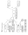
- FIG. 3 shows a simple embodiment of an MC-MU scenario (MU: multi-user / multi-participant) with nested (Interleaving) FDMA technique.
- the left side of FIG. 3 represents the case of an uplink scenario in which two Participants or users via their stations MSu or MSu + 1 for the transmission over the radio interface V a total number N of 8 frequency subcarriers fo + ⁇ f, fo + 2 ⁇ f, ...., fo + 8 ⁇ f des share available frequency band.
- the total number U of Participant is 2, whereby the number M of Subehr fi pro Participant 4 amounts to and in each case a frequency distance of ⁇ f.
- the first participant or his station MSu be according to the nesting principle or interleaving to transmit four consecutive data from one Symbol block of the first, third, fifth and seventh subcarriers assigned. For the other subcarriers will be zero values provided.
- the data block thus generated becomes a modulation device Mod supplied, which modulates the block and a transmitter TX.
- the so prepared Data is transmitted via the radio interface V in the upward direction UL transmitted to the base station BS.
- the second subscriber station MSu + 1 provided four data symbols, these in a symbol block the second, fourth, sixth and eighth position be assigned.
- the other positions, which of the first station MSu have been assigned, are with Zero values filled.
- the symbol block becomes a Modulation device Mod supplied, which is a modulation on the frequency band or the individual subcarrier makes.
- the data obtained are transmitted via a transmission device TX and transmit the radio interface V to the base station BS.
- the illustrated embodiment finds a communication between the first and second mobile stations as participant-side stations, so that the data of the second station MSu + 1 in the downward direction DL to the first subscriber side Mobile station MSu be transferred and the data from the first subscriber-side mobile station MSu in the downward direction DL to the second subscriber-side mobile station MSu + 1 are transmitted.
- the stations corresponding receiving devices RX To receive the stations corresponding receiving devices RX.
- Such a nested frequency mapping is in particular advantageous in that it provides the frequency diversity required in the Radio channel inherently available, used efficiently.
- everyone Participants or the corresponding stations transmit their Data on a given set of maximally spaced subcarriers within the available bandwidth.
- the well-known method for implementing a nested Subcarrier assignment [5] is the MC symbol build up from N subcarriers and zero values to the subcarriers assign, which by other participants or stations be occupied.
- each participant a block of length N with M symbols, which be separated by U-I zero values, i. N-M zero values are added to each block of N symbols.
- the block is then MC modulated on N subcarrier, in the OFDM case by an IFFT operation, which is a waste of computing power is because many of the samples (samples) are null values, but still provided a correspondingly large computational complexity must become.
- the complexity of a billing process is a key aspect during the design process of a communication system, especially if the subscriber station or the Subscriber terminal is considered.
- a high complexity directly causes correspondingly high costs, a corresponding one Size and corresponding power consumption, i. shortens the battery life, the subscriber equipment.
- the values thus replicated are each fed to a so-called prototype filter H (f).
- the data or data symbols a m (n / T) are complex values which are obtained via a previous bit mapping.
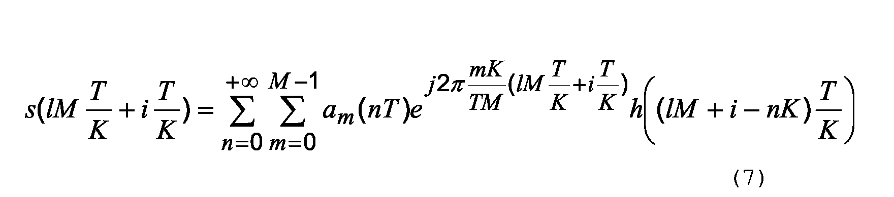
- Each of these values is oversampled by the factor K ⁇ M and filtered by the same prototype filter, whereupon each spectrum is arranged by a subcarrier frequency f m by multiplication by the exponential factor e j2 ⁇ fo ⁇ nT / K.
- the system is referred to as not being critically sampled if the oversampling factor is greater than the number of subcarriers, ie, K> M.
- each block of M input samples or K input data is assigned output samples, so that some degree of redundancy is introduced. This redundancy is used to increase the subcarrier spacing given by K / MT.
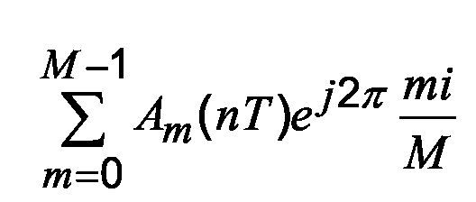
- a i (nT) is the same the inverse discrete Fourier transform, which allows a transformation to
- the output signal s (t (T / K)) at time k is obtained by convolution of the (k mod M) th IDFT output value with the (k mod K) -th polyphase filter component for K.
- the object of the invention is to provide a method and a device for mapping data symbols of a data source or a subscriber to one of the data sources or associated with the subscriber number of mutually separated Subcarriers of a variety of subcarriers of a multi-carrier system with a view to the calculation effort and the corresponding Improve complexity.
- too Provided methods or devices for a back image become.
- a first, transmitter-side solution consists of a procedure for mapping data from a data source of a station one of the station assigned number of subcarriers one Variety of subcarriers of a multi-carrier system in which a Sequence of station data to separate other data modulated on mutually evenly spaced subcarrier is used, where modulating the data only the assigned Subcarriers are modulated.
- a preferably such a method implementing device is to map data from a data source to a number of mutually separated data sources Subcarriers of a variety, in particular total number of subcarriers a multi-carrier system with a data source for Providing a sequence of data, a modulation means for modulating the data on the subcarriers and a Output device designed to output the processed data, wherein the modulation means for modulating only the associated subcarrier is arranged and formed.
- a second, receiver-side solution consists of a procedure for reconstructing data in a data receiving Station where the data is about a number of the data associated subcarrier of a carrier with a plurality, in particular Total number of subcarriers of a multicarrier system and the associated subcarriers to separate the data of the station from each other evenly are spaced apart, wherein in the re-mapping only received data the assigned subcarrier are processed.
- a preferably such a method implementing device is designed to reconstitute data, the Data about a number to the device and / or to the data assigned subcarrier of a carrier with a plurality, in particular total number of subcarriers of a multi-carrier system and the associated subcarriers to separate the data from each other evenly spaced and a demodulation device for demodulating the data received via the subcarriers, wherein the Demodulation device for demodulating over only the assigned subcarrier received data to the re-imaged Data is formed.
- the device in modulating the Data symbols modulated only the assigned subcarrier or when mapping back only processed data of the associated subcarrier.
- the device is the modulation device configured such that these according to only the subcarrier which modulates the data of the data source or the Associated with the subscriber. Accordingly also with the Reverse mapping made only a reduced demodulation.
- To separate is at least one subcarrier for other data between each two adjacent associated sub-carriers intermediately.
- the devices are in particular for performing designed such methods.
- a multiplication by an exponential factor is performed, in particular a multiplication by the factor e j2 ⁇ funT / K with ⁇ f as distance of the subcarriers, u as assigned index from a group to the total number of subcarriers, and nT / K as time index.
- the modulation is preferably by a Fourier transformation, in particular an inverse fast Fourier transformation, performed on only the assigned subcarriers. After modulation, a repetition of the modulated Data performed. To separate the distance of the associated subcarrier thereby preferably based on a non-critical Oversampling set.
- MC multi-carrier system
- an OFDM-MC system is preferably used as the multi-carrier system.
- the number of corresponding subcarriers is preferably successively a modulation in the form of an inverse fast Fourier transform on the supplied data carried out a repetition of the respective modulated data performed according to the number of stations, one Parallel / serial conversion performed on an output line and a multiplication of the obtained data with a exponential factor taking into account the distance of the Subcarrier, a group number of the station from the number of Stations and a running index performed.
- a device for modulating data preferably has a repetition means for multiplying by the Modulation device each output data, wherein the repetition device downstream of the modulation device is.
- a multiplication device is used to multiply the processed data before output by an exponential factor for shifting to other frequencies, in particular with the factor e j2 ⁇ funT / K with ⁇ f as distance of the subcarriers, u as assigned index from a group to the plurality of subcarriers split participants and nT / K as time index.
- a multiplication with a factor shifting the assigned subcarriers is applied according to a preferred method, in particular with the factor e -j2 ⁇ funT / K with ⁇ f as distance of the subcarriers, u as assigned index from a group to the multiplicity of subcarriers split participant and nT / K as time index.
- a serial / parallel conversion is applied to the number of assigned subcarriers.
- another serial / parallel conversion to the number of stations to which subcarriers have been assigned is applied to the data, whereupon the data obtained from the second serial / parallel conversion are respectively summed up.
- a demodulation in particular Fourier transformation (FFT) will be remapped to the remaining data for deployment Data applied.
- FFT Fourier transformation
- a number corresponding to a number of repetitions with assigned subcarriers complex multiplication is performed, in particular with a factor e -j2 ⁇ ukT / K , a serial / parallel conversion of 1 to the number of station ( MS1) assigned to each of the data obtained, a serial / parallel conversion to the number of stations with associated subcarriers is performed, the data respectively obtained in the second serial / parallel conversions are summed and the remaining data is a Demodulation, in particular a Fourier transform (FFT) applied.
- FFT Fourier transform
- An apparatus for demodulating received data preferably by performing a corresponding method, comprises multiplication means for multiplying the received data by a factor, in particular an exponential factor e -j2 ⁇ f ⁇ u ⁇ nT / N with ⁇ f as distance of the subcarriers, u as associated Index from a group on the multiplicity of subcarriers split participants and nT / K as time index.
- a factor in particular an exponential factor e -j2 ⁇ f ⁇ u ⁇ nT / N with ⁇ f as distance of the subcarriers, u as associated Index from a group on the multiplicity of subcarriers split participants and nT / K as time index.
- a serial / parallel conversion device is used for conversion the received or multiplied data to a number of lines, which is the number of assigned subcarriers equivalent.
- a further serial / parallel conversion device at each one of outputs from the above serial / parallel conversion device is used for respectively converting the converted data to a number corresponding to the number of stations with associated subcarriers of wires.
- the second serial / parallel conversion devices are addition means for adding up assigned to the values on their output lines.
- the demodulation device only serves to demodulate the processed and received via the associated subcarrier Data for reconstructing the data.
- a multiplication with an exponential factor for shifting is performed.
- This can be carried out in particular by the factor e + j2 ⁇ funT / K for shifting the subcarriers, where ⁇ f is used as the distance of the subcarriers, u as an assigned index from a group of subscribers divided into subcarriers and nT / K as the time index.
- the corresponding negative sign is used instead of the positive one.
- a modulation is made possible by a per se known Fourier transformation, in particular Fast Fourier Transformation, on assigned subcarriers.
- oversampling factor K (Oversampling factor).
- M (U-1) subcarriers are different Assigned to subscribers or stations.
- K M * U used.
- the multiplication with the Moves the exponential factor in a subsequent step the set of M uniform and maximally spaced subcarriers relative to the sentences of the other stations.
- Each participant or each station modulates or demodulates only their own associated subcarrier without the benefits of fast digital implementation of the MC modulation scheme to lose.
- the mobile station MS2 has a variety of components, where present only the components are shown, which are for understanding the method of mapping the data symbols are required on the associated subcarrier.
- the mobile Station MS2 are e.g. the second, fourth, sixth and eighth subcarriers f1, f3, f5, f7 assigned.
- MS2 can also be special provided for the process trained stations.
- MS2 can also be special provided for the process trained stations.
- Hardware elements In addition to the implementation of individual components by Hardware elements is also an implementation by a corresponding software control of a reduced number of Components, in particular a central processor chip possible.
- the station MS2 has a central control device C and a memory MEM for storing data and control programs on.
- a remote Station in particular base station BS to be transmitted data ..., d1, d2, d3, d4, ... are provided by a data source DS.
- the data source DS sequentially outputs the Data values, wherein according to the preferred embodiment for the present constellation also a parallel Output over four data lines, each with four consecutive Data or data symbols d1, ..., d4 done can.
- a data block db with a number is output of data or data symbols d1, ..., d4, respectively the number m of subcarriers assigned to station MS2 are.
- the modulation device IFFT preferably carries out the modulation on M subcarriers with the aid of an inverse fast Fourier transformation.
- the modulation device IFFT may have a single serial or preferably a plurality of parallel output lines for outputting the modulated data or data symbols d1 * , d2 * , d3 * , d4 * .
- the data d1 * , ..., d4 * output by the modulator IFFT are supplied to a repetition means REP receiving the respective data d1 * , d2 * , d3 * and d4 * , respectively and multiply issues.
- the multiplication corresponds to the value of the total number U of subscribers, in the present case 2.
- the modulated data blocks fb * provided by the repeater REP are supplied to a parallel / serial converter P / S, which converts the M input lines to an output line.
- a multi-carrier or MC symbol fb * is output.
- two successive data blocks fb * with the modulated data d1 * , d2 * , d3 * , d4 * are available at the output of the repetition device or the plurality of repetition devices REP.
- These data values are assigned to individual subcarriers such that the first, third, fifth and seventh subcarriers f0, f2, f4, f6 are assigned to the data values.
- the distance between the subcarriers to one another corresponds to U times the difference .DELTA.f between two individual, directly adjacent sub-carriers f0, f1.
- the required spacing of subcarriers f0, f2, f4, f6 or f1, f3, f5, f7 is determined by oversampling for each Attained participants or his station. However, it will be in a first step only the group of the associated ones Subcarrier f0, f2, f4, f6 taken into account for the first station MS1. However, the second station MS2 is the second group associated with the subcarriers f1, f3, f5, f7 assigned to one another, which compared to the first group to the frequency difference ⁇ f is shifted.
- the MC symbol is supplied to a multiplier MULT, the supplied modulated data being multiplied by an exponential factor.
- the exponential factor takes into account the still missing spacing of the output subcarriers between the individual stations MS1 or MS2. Depending on the exponential value, the exponential factor leads to a shift of the subcarriers.
- the exponential factor is built up by e j2 ⁇ f ⁇ u ⁇ nT / N ,
- the station number u 0, so that a multiplication by the factor 1 is performed.
- the MC symbol is thus not changed with respect to its associated frequencies, so that the MC symbol fb ° after the multiplication has data associated with the first, third, fifth and seventh subcarriers f0, f2, f4, f6.
- the station number u 1, which multiplies by the factor e j2 ⁇ f ⁇ 1 ⁇ nT / N , is carried out. This corresponds to a frequency shift around the simple frequency difference ⁇ f, so that the modulated data values d1 * , ... are now assigned to the offset second, fourth, sixth and eighth subcarriers f1, f3, f5 and f7, respectively.
- the multiplied MC symbol is finally a digital / analog conversion device DAC for analogizing and a Transmitting device TX supplied.
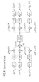
- the device or a suitably designed method thus reduce the required computational complexity of Station or terminal MS1, MS2 of the subscriber on the Sender side in the uplink scenario and accordingly also on the Receiver side in the downlink scenario by re-sorting the general implementation of a non-critical sampled (sampled) Filterbank (FB) MC modulation system, as is clear from G. Cherubini et al. [7] is known and will be described below with reference to FIG 4.
- FB Filterbank
- the occupancy / reconversion (allocation / deallocation) implementing a MU-MC nested FDMA system with a much lower complexity in terms of commonly used approximation.
- the implementation is achieved by boosting the desired MC modulation as the general non-critically sampled FB-MC modulation and using an oversampling factor (Oversampling factor) implemented to introduce MU access.
- the participants or their stations do not send any null values on the subcarriers, which other participants or their Stations are assigned.
- the stations carry an MC modulation however, only on their own assigned subcarriers by.
- the application finds in the case of the OFDM system, where the MC modulation implemented on N samples via the IFFT operation where N equals the number of subcarriers.
- OFDM systems become one scored low complex nested subcarrier arrangement, as follows.
- the settings are sufficient for all assumptions the for a quick digital implementation of the general not critically sampled FB-MC modulation by a fast Fourier transformation using benches Polyphase filters are required. Therefore, every participant or each station the multi-carrier transmission over their M assigned subcarrier by performing the inverse fast Fourier transform to M samples or data or implementing data symbols, followed by filtering to every initial value of the inverse fast Fourier transform a periodically time-variant polyphase component with respect to the factor K of the prototype filter is carried out.
- This also applies to the case of a polyphase filter with a shape other than the rectangle. Under the Assume that the prototype filter is a rectangular shape in the time domain has its polyphase components always as time invariant Kronecker A functions, where they do not contribute. In the latter case offers the Use of OFDM with the described repetition instead the polyphase filter advantageous.
- the introduction of a redundancy is effected by a repetition or repetition of the output values of the inverse fast Fourier transformation by a factor of threefold.
- the transmission of the data of the station of the individual subscriber to M equally spaced subcarriers, the 0th, the Uth, the 2Uth, ... (the MU (U-1) -th ) is efficiently implemented without the transmission of unnecessary zero values.
- an additional frequency shift is then implemented in the digital domain, which assigns different subscribers or their stations different sets of equally spaced subcarriers.
- the implementation is thus according to the method of the Carrying out a modulation, especially inverse fast Fourier transform to M samples or data, one U-fold repetition, a parallel processing of a parallel-serial conversion from U to 1 and a multiplication with an exponential factor.
- a modulation especially inverse fast Fourier transform to M samples or data, one U-fold repetition, a parallel processing of a parallel-serial conversion from U to 1 and a multiplication with an exponential factor.
- a modulation especially inverse fast Fourier transform to M samples or data, one U-fold repetition, a parallel processing of a parallel-serial conversion from U to 1 and a multiplication with an exponential factor.
- the computational effort in the modulation can also the computational effort in the demodulation in appropriate Way to be reduced.
- a base station transmits BS data via a radio interface V to the subscriber or to its mobile station MS1, being in turn for transmission a given set of subcarriers f0, f2, f4, f6 for used an exemplary MC-FDMA application with interleaving becomes.
- Over the radio interface V are also more Data on further stations on further subcarriers of the Transfer available carrier tape.
- the station MS1 of the subscriber recorded in the illustrated Embodiment only their own data, so used a kind of individual participant detection, whereby the data on the other subcarriers are ignored. Therefore exists for the Station MS1 does not require MC demodulation of all Perform subcarrier, for example by means of a fast Fourier transform FFT at OFDM. This brings with it the classic approach, where each station is all subcarriers MC-demodulated and then subsequently to the other Subscribers assigned subcarriers received data throws away the advantage of a significantly reduced computational complexity.
- a preferred embodiment for a reduced MC demodulation may be provided by a fast implementation scheme which may be used for an OFDM-MC system by, for example, selecting an arrangement and adjustment as is known per se from [3] and applying to the Receiver side of the oversampled FB-MC system, as is known per se from [7].
- the preferred implementation for use with a reduced number of subcarriers to be considered includes the steps of K complex multiplies with the factor e -j2 ⁇ ukT / K, followed by serial to parallel conversion of 1 to M, M serial to parallel conversion from 1 to U, M (U-1) summations and a Fourier transform FFT to M samples.
- the complexity of the mathematical calculations can be expressed by the number of complex multiplies, which in turn gives K + M log M, as was the case in the uplink case. This is a significant reduction compared to the effort of the classical approach with K log K required complex multiplications.
- the downlink scenario of the present approach provides the same improvement or gain in terms of complexity as the uplink. The profit depends on the number of participants in the system.
- the station MS1 has a receiving device RX for receiving the data transmitted via the radio interface V, wherein the transmitting and receiving device can also be designed as a combined device.
- the received data is supplied to an analog / digital converter ADC, which converts into digital data.
- ADC analog / digital converter
- These digital data are supplied to a multiplier to be multiplied therein with the exponent e -j2 ⁇ fukT / K.
- the multiplication result is supplied to a serial / parallel converter S / P for conversion to M output lines.
- Each of the output lines leads to another serial to parallel converter for converting the received data to U output lines.
- the values of these U output lines are supplied to an addition device having at least one adder ADD and added thereto.
- the resulting M output lines of the addition devices ADD are supplied to the inputs of a demodulation device FFT.
- the demodulation in the demodulation device FFT is advantageously converted to M data values by a fast Fourier transformation.
- the M output lines of the demodulation device FFT finally provide the reconstructed data or data symbols d1, d2, d3, d4, which are fed to an output or to a further processing device X.
- the control of the process is in turn carried out by a central control device C. It is also possible to completely or partially implement the structural arrangement in a software solution, ie in a procedural solution of the individual steps described.
- the station MS1 also has a memory MEM, among other things, in which the program routines and communication parameters required for the specific application are stored.
- MEM the program routines and communication parameters required for the specific application are stored.
- the multitude N of subcarriers f0, f1, ..., f7 evenly on the number U is distributed by stations MS1, MS2.
- they are also other allocation schemes for subcarriers possible.
- preference is given to assignment schemes in which starting from a base number of assigned subcarriers, z. B. 2 or 4 a station, each a multiple of this Base number of subcarriers. Accordingly then the modulation device or demodulation device be formed correspondingly more extensive, the different Number in the repetition device REP and in multiplication by selecting suitable factor parameters or with the multiplication element MULT is.
- each station MS1, MS2 modulates only the M subcarriers associated with it, is based in the simplest embodiment on the idea that all stations transmit and receive M with the same number M of subcarriers.
- This frequency shift is implemented in the digital domain, being constant and also different for the different stations.
- the modulation or the Fourier transformation does not depend on the oversampling factor K but only on the number M of assigned subcarriers. This allows each station to perform a Fourier transform over only the number of subcarriers it uses.
- the IDFT operation (IDFT: Inverse Discrete Fourier Transformation) does not depend on the oversampling factor K but only on the number M of subcarriers used, taking into account the non-critically sampled case. This means that each station performs a Fourier transformation only over the number M of carriers used by that station.
Landscapes
- Engineering & Computer Science (AREA)
- Signal Processing (AREA)
- Computer Networks & Wireless Communication (AREA)
- Mobile Radio Communication Systems (AREA)
- Digital Transmission Methods That Use Modulated Carrier Waves (AREA)
Abstract
Description




- FIG 1
- Komponenten einer sendenden Station eines Teilnehmers;
- FIG 2
- Komponenten einer empfangenden Station eines Teilnehmers;
- FIG 3
- Stationen verschiedener Teilnehmer, welche mit einer Basisstation kommunizieren und eine Datenverarbeitung zum Senden gemäß dem Stand der Technik durchführen; und
- FIG 4
- ein Filterbank-Mehrträger-Schema.
Claims (20)
- Verfahren zum Abbilden von Daten (d1, d2, d3, d4) einer Datenquelle (DS) einer Station (MS2) auf eine der Station (MS2) zugeordnete Anzahl (M) von Subträgern (f1, f3, f5, f7) einer Vielzahl (N) von Subträgern (f0, f1, ... f7) eines Mehrträger-Systems, bei dem eine Folge der Daten (d1, ... d4) der Station (MS2) zum Separieren von weiteren Daten auf zueinander gleichmäßig beabstandete der Subträger (f1, f3, f5, f7) moduliert wird,
dadurch gekennzeichnet, dass
beim Modulieren der Daten (d1, ... d4) nur die der Station (MS2) zugeordneten Subträger (f1, f3, f5, f7) moduliert werden. - Verfahren nach Anspruch 1, bei dem
zum Verschieben der zugeordneten Subträger eine Multiplikation mit einem exponentiellen Faktor durchgeführt wird. - Verfahren nach einem vorstehenden Anspruch, bei dem
zum Separieren der Abstand der zugeordneten Subträger (f1, f3, f5, f7) anhand einer nicht-kritischen Überabtastung festgelegt wird. - Verfahren nach einem vorstehenden Anspruch, bei dem
nach der Modulation eine Repetition der modulierten Daten (d1*, d2*, d3*, d4*) durchgeführt wird. - Verfahren nach einem vorstehenden Anspruch, bei dem
die Modulation mittels einer Fourier-Transformation (IFFT) auf die zugeordneten Subträger (f1, f3, f5, f7) durchgeführt wird. - Verfahren nach einem vorstehenden Anspruch, bei dem
auf eine aufeinanderfolgende Anzahl von Daten (d1, ... d4), die der Anzahl (M) von zugeordneten Subträgern (f1, f3, f5, f7) entspricht,eine Modulation mittels einer inversen schnellen Fourier-Transformation (IFFT) auf die zugeführten Daten durchgeführt wird,eine Repetition der jeweiligen modulierten Daten (d1*, d2*, d3*, d4*) entsprechend der Anzahl (U) von Stationen (MS1, MS2) durchgeführt wird,eine Parallel-/Seriell-Umsetzung auf eine Ausgangsleitung durchgeführt wird, undeine Multiplikation der modulierten Daten (d1*, d2*, d3*, d4*) mit einem exponentiellen Faktor unter Berücksichtigung eines Abstands (Δf) der Subträger (f0, f1, ..., f7), einer Gruppennummer (u) der Station (MS2) aus der Anzahl (U) der Stationen (MS1, MS2) und einem Laufindex durchgeführt wird. - Vorrichtung in einer Station (MS2) eines Kommunikationssystems zum Abbilden von Daten (d1, d2, d3, d4) einer Datenquelle (DS) auf eine der Datenquelle zugeordnete Anzahl (M) von zueinander separierten Subträgern (f1, f3, f5, f7) einer Vielzahl (N) von Subträgern (f0, f1, ..., f7) eines Mehrträger-Systems, mitdadurch gekennzeichnet, dasszumindest einer Datenquelle (DS) zum Bereitstellen einer Folge von Daten (d1, d2, d3, d4),einer Modulationseinrichtung (IFFT) zum Modulieren der Daten (d1, ..., d4) auf die Subträger (f1, f3, f5, f7) undeiner Ausgabeeinrichtung (TX) zum Ausgeben der verarbeiteten Daten,die Modulationseinrichtung (IFFT) zum Modulieren nur der der Station (MS2) zugeordneten Subträger (f1, f3, f5, f7) ausgebildet ist.
- Vorrichtung nach Anspruch 7, mit
einer der Modulationseinrichtung (IFFT) nachgeschalteten Repetitionseinrichtung (REP) zum Vervielfachen der durch die Modulationseinrichtung (IFFT) jeweils ausgegebenen Daten (d1*, d2*, d3*, d4*). - Vorrichtung nach Anspruch 7 oder 8,
mit einer Multiplikationseinrichtung (MULT) zum Multiplizieren der modulierten Daten (d1*, d2*, ...) mit einem exponentiellen Faktor zum Verschieben zu anderen Frequenzen. - Verfahren zum Rückabbilden von Daten (d1, d2, d3, d4) in einer die Daten empfangenden Station (MS1), bei dem die Daten über eine Anzahl (M) den Daten zugeordneter Subträger (f0, f2, f4, f6) eines Trägers mit einer Vielzahl (N) von Subträgern (f0, f1, ..., f7) eines Mehrträger-Systems empfangen werden, und wobei die zugeordneten Subträger zum Separieren der Daten der Station voneinander gleichmäßig beabstandet sind,
dadurch gekennzeichnet, dass
beim Rückabbilden nur empfangene Daten der zugeordneten Subträger (f0, f2, f4, f6) verarbeitet werden. - Verfahren nach Anspruch 10, bei dem
auf die empfangenen Daten eine Multiplikation mit einem die zugeordneten Subträger verschiebenden Faktor angewendet wird. - Verfahren nach Anspruch 11, bei dem
auf die multiplizierten Daten eine Seriell-/Parallel-Umsetzung auf die Anzahl (M) der zugeordneten Subträger angewendet wird. - Verfahren nach Anspruch 12, bei dem
auf die Daten eine weitere Seriell-/Parallel-Umsetzung auf jeweils die Anzahl (U) Stationen (MS1, MS2), welchen Subträger zugeordnet wurden, angewendet wird, und bei dem die aus der weiteren Seriell-/Parallel-Umsetzung erhaltenen Daten jeweils aufsummiert werden. - Verfahren nach einem der Ansprüche 10 bis 13, bei dem eine Demodulation (FFT) auf die verbleibenden Daten zum Bereitstellen rückabgebildeter Daten angewendet wird.
- Verfahren nach einem der Ansprüche 10 bis 14, bei demauf die empfangenen Daten eine Anzahl (K), welche einer Anzahl von Repetitionen (U) mit zugeordneten Subträgern entspricht, komplexer Multiplikationen durchgeführt wird,eine Seriell-/Parallel-Umsetzung von 1 auf die Anzahl (M) der Station (MS1) zugeordneter Subträger durchgeführt wird,auf die erhaltenen Daten jeweils eine Seriell-/Parallel-Umsetzung auf die Anzahl (U) der Stationen (MS1, MS2) mit zugeordneten Subträgern durchgeführt wird,die bei den zweiten Seriell-/Parallel-Umsetzungen jeweils erhaltenen Daten aufsummiert werden, undauf die verbleibenden Daten eine Demodulation (FFT) angewendet wird.
- Vorrichtung in einer Station (MS) eines Kommunikationssystems zum Rückabbilden von Daten (d1, d2, d3, d4), wobei die Daten über eine Anzahl (M) der Vorrichtung (MS) und/oder den Daten zugeordneter Subträger (f0, f2, f4, f6) eines Trägers mit einer Vielzahl (N) von Subträgern (f0, f1, ..., f7) eines Mehrträger-Systems empfangen werden, und wobei die zugeordneten Subträger zum Separieren der Daten voneinander gleichmäßig beabstandet sind, miteiner Demodulationseinrichtung (FFT) zum Demodulieren der über die Subträger empfangenen Daten, dadurch gekennzeichnet, dassdie Demodulationseinrichtung zum Demodulieren von über nur die zugeordneten Subträger (f0, f2, f4, f6) empfangenen Daten zu den rückabgebildeten Daten (d1, ..., d4) ausgebildet ist.
- Vorrichtung nach Anspruch 16, mit
einer Multiplikationseinrichtung (MULT) zum Multiplizieren der empfangenen Daten mit einem Faktor. - Vorrichtung nach Anspruch 16 oder 17, mit
einer Seriell-/Parallel-Umsetzungseinrichtung zum Umsetzen der empfangenen bzw. multiplizierten Daten auf eine Anzahl von Leitungen, welche der Anzahl (M) zugeordneter Subträger entspricht. - Vorrichtung nach Anspruch 18, mitje einer weiteren Seriell-/Parallel-Umsetzungseinrichtung (S/P) an jeweils einem von Ausgängen aus der vorstehenden Seriell-/Parallel-Umsetzungseinrichtung (S/P) zum jeweiligen Umsetzen der umgesetzten Daten auf eine Anzahl (U) entsprechend der Anzahl von Stationen (MS1, MS2) mit zugeordneten Subträgern von Leitungen, undden weiteren Seriell-/Parallel-Umsetzungseinrichtungen (S/P) zugeordneten Additionseinrichtungen (ADD) zum Aufaddieren der Werte auf deren Ausgangsleitungen.
- Vorrichtung nach einem der Ansprüche 16 bis 19, mit der Demodulationseinrichtung (FFT) zum Demodulieren nur der verarbeiteten und über die zugeordneten Subträger (f0, f2, f4, f6) empfangenen Daten zum Rückabbilden der Daten (d1, ..., d4).
Applications Claiming Priority (2)
| Application Number | Priority Date | Filing Date | Title |
|---|---|---|---|
| DE10345434 | 2003-09-30 | ||
| DE10345434 | 2003-09-30 |
Publications (2)
| Publication Number | Publication Date |
|---|---|
| EP1521389A2 true EP1521389A2 (de) | 2005-04-06 |
| EP1521389A3 EP1521389A3 (de) | 2006-12-06 |
Family
ID=34306167
Family Applications (1)
| Application Number | Title | Priority Date | Filing Date |
|---|---|---|---|
| EP04104205A Withdrawn EP1521389A3 (de) | 2003-09-30 | 2004-09-02 | Verfahren und Vorrichtungen zum Abbilden von Daten auf Subträger eines Mehrträgersystems bzw. zum Rückabbilden |
Country Status (2)
| Country | Link |
|---|---|
| EP (1) | EP1521389A3 (de) |
| KR (1) | KR100691049B1 (de) |
Families Citing this family (1)
| Publication number | Priority date | Publication date | Assignee | Title |
|---|---|---|---|---|
| DE102008018385A1 (de) * | 2008-04-11 | 2009-10-15 | Rohde & Schwarz Gmbh & Co. Kg | Testgerät zum Testen der Übertragungsqualität eines Funkgeräts |
-
2004
- 2004-09-02 EP EP04104205A patent/EP1521389A3/de not_active Withdrawn
- 2004-09-25 KR KR1020040077553A patent/KR100691049B1/ko not_active Expired - Fee Related
Non-Patent Citations (1)
| Title |
|---|
| None * |
Also Published As
| Publication number | Publication date |
|---|---|
| EP1521389A3 (de) | 2006-12-06 |
| KR20050031976A (ko) | 2005-04-06 |
| KR100691049B1 (ko) | 2007-03-09 |
Similar Documents
| Publication | Publication Date | Title |
|---|---|---|
| DE69934866T2 (de) | Vollduplexübertragung mit Mehrträgermodulation | |
| DE69330964T2 (de) | Verfahren und anordnung zur dynamischen zuteilung mehrerer trägerwellenkanäle für mehrfachzugriff durch frequenzmultiplex | |
| DE69434353T2 (de) | Mehrträger-Frequenzsprungkommunikationssystem | |
| DE69633670T2 (de) | Pulsformung für mehrträgermodulation | |
| DE60133006T2 (de) | Gleitfensterverarbeitung zum empfang von mehrträgersignalen | |
| DE60303109T2 (de) | Verfahren und Vorrichtung zur Auswahl von Unterträgern gemäss Dienstqualitätsanforderungen in einem Mehrträgerkommunikationssystem | |
| DE60129884T2 (de) | Einrichtung zur Mehrträgermodulation sowie -Multiplexierung | |
| EP2439870B1 (de) | Verfahren zum Erzeugen von Sendesignalen bzw. OFDM-Symbolen in einem Komminikationssystem und Kommunikationssystemvorrichtung | |
| EP2103070B1 (de) | Verfahren bzw. ofdm-vorrichtung zur sc-fdma-datenübertragung | |
| DE102019117363B4 (de) | Diskontinuierliche Schnellfaltungsbasierte Filterverarbeitung | |
| DE202005022046U1 (de) | Funksender und Funkempfänger | |
| DE60125925T2 (de) | Referenzsymbole zur Kanalschätzung bei Mehrträgerübertragung | |
| DE602004010684T2 (de) | Verfahren und system zur übertragung von informationsdaten über eine kommunikationsleitung unter verwendung von gefilterter multiton-modulation (fmt) | |
| DE69922176T2 (de) | Verbesserungen bei vdsl | |
| DE10294307B4 (de) | Verfahren zum Übertragen von Daten durch Mehrträger-Modulation | |
| DE69929871T2 (de) | Verfahren und Vorrichtung für Mehrfachzugriff in einem Kommunikationssystem | |
| DE60201620T2 (de) | Vorrichtung und Verfahren zur Datenkommunikation basierend auf OFDM | |
| DE19838295B4 (de) | Adaptive Subträgerselektion zur Verringerung der Spitzenwerte eines Multiträger-Signals | |
| DE69937178T2 (de) | Spreizspektrumübertragungssystem mit einer gefilterten Mehrträgermodulation | |
| DE60318754T2 (de) | Mehrträgersystem mit sendediversität | |
| DE4227990C2 (de) | Funkübertragungsverfahren mittels einer ortsfesten Basisstation und einer Vielzahl voneinander unabhängiger ortsfester Basisstationen | |
| DE69811688T2 (de) | Digitale übertragung mit teilbandkodierung | |
| DE19827514A1 (de) | Adaptive Subträgerselektion zur optimierten Übertragung eines Multiträger-Signals | |
| DE102004045075B4 (de) | Verfahren und Vorrichtung zur Aussparung einstellbarer schmaler Frequenzbänder in einem breitbandigen Sendesignal | |
| DE202006006460U1 (de) | Hybrides orthogonales Frequenzmultiplex-Vielfachzugriffsystem |
Legal Events
| Date | Code | Title | Description |
|---|---|---|---|
| PUAI | Public reference made under article 153(3) epc to a published international application that has entered the european phase |
Free format text: ORIGINAL CODE: 0009012 |
|
| AK | Designated contracting states |
Kind code of ref document: A2 Designated state(s): AT BE BG CH CY CZ DE DK EE ES FI FR GB GR HU IE IT LI LU MC NL PL PT RO SE SI SK TR |
|
| AX | Request for extension of the european patent |
Extension state: AL HR LT LV MK |
|
| PUAL | Search report despatched |
Free format text: ORIGINAL CODE: 0009013 |
|
| AK | Designated contracting states |
Kind code of ref document: A3 Designated state(s): AT BE BG CH CY CZ DE DK EE ES FI FR GB GR HU IE IT LI LU MC NL PL PT RO SE SI SK TR |
|
| AX | Request for extension of the european patent |
Extension state: AL HR LT LV MK |
|
| RIC1 | Information provided on ipc code assigned before grant |
Ipc: H04L 27/26 20060101ALI20061027BHEP Ipc: H04L 5/02 20060101AFI20050209BHEP |
|
| 17P | Request for examination filed |
Effective date: 20070108 |
|
| 17Q | First examination report despatched |
Effective date: 20070219 |
|
| AKX | Designation fees paid |
Designated state(s): AT BE BG CH CY CZ DE DK EE ES FI FR GB GR HU IE IT LI LU MC NL PL PT RO SE SI SK TR |
|
| RAP1 | Party data changed (applicant data changed or rights of an application transferred) |
Owner name: NOKIA SIEMENS NETWORKS GMBH & CO. KG |
|
| RAP3 | Party data changed (applicant data changed or rights of an application transferred) |
Owner name: NOKIA SIEMENS NETWORKS S.P.A. |
|
| RAP3 | Party data changed (applicant data changed or rights of an application transferred) |
Owner name: NOKIA SIEMENS NETWORKS GMBH & CO. KG |
|
| STAA | Information on the status of an ep patent application or granted ep patent |
Free format text: STATUS: THE APPLICATION IS DEEMED TO BE WITHDRAWN |
|
| 18D | Application deemed to be withdrawn |
Effective date: 20090401 |