EP1521253B1 - Recording medium having position recognition structure, and position recognition apparatus and method - Google Patents
Recording medium having position recognition structure, and position recognition apparatus and method Download PDFInfo
- Publication number
- EP1521253B1 EP1521253B1 EP04020636A EP04020636A EP1521253B1 EP 1521253 B1 EP1521253 B1 EP 1521253B1 EP 04020636 A EP04020636 A EP 04020636A EP 04020636 A EP04020636 A EP 04020636A EP 1521253 B1 EP1521253 B1 EP 1521253B1
- Authority
- EP
- European Patent Office
- Prior art keywords
- line
- line segments
- recording
- intersection
- recording medium
- Prior art date
- Legal status (The legal status is an assumption and is not a legal conclusion. Google has not performed a legal analysis and makes no representation as to the accuracy of the status listed.)
- Expired - Fee Related
Links
Images


Classifications
-
- G—PHYSICS
- G11—INFORMATION STORAGE
- G11B—INFORMATION STORAGE BASED ON RELATIVE MOVEMENT BETWEEN RECORD CARRIER AND TRANSDUCER
- G11B9/00—Recording or reproducing using a method not covered by one of the main groups G11B3/00 - G11B7/00; Record carriers therefor
- G11B9/12—Recording or reproducing using a method not covered by one of the main groups G11B3/00 - G11B7/00; Record carriers therefor using near-field interactions; Record carriers therefor
- G11B9/14—Recording or reproducing using a method not covered by one of the main groups G11B3/00 - G11B7/00; Record carriers therefor using near-field interactions; Record carriers therefor using microscopic probe means, i.e. recording or reproducing by means directly associated with the tip of a microscopic electrical probe as used in Scanning Tunneling Microscopy [STM] or Atomic Force Microscopy [AFM] for inducing physical or electrical perturbations in a recording medium; Record carriers or media specially adapted for such transducing of information
- G11B9/1463—Record carriers for recording or reproduction involving the use of microscopic probe means
- G11B9/1472—Record carriers for recording or reproduction involving the use of microscopic probe means characterised by the form
- G11B9/1481—Auxiliary features, e.g. reference or indexing surfaces
-
- B—PERFORMING OPERATIONS; TRANSPORTING
- B82—NANOTECHNOLOGY
- B82Y—SPECIFIC USES OR APPLICATIONS OF NANOSTRUCTURES; MEASUREMENT OR ANALYSIS OF NANOSTRUCTURES; MANUFACTURE OR TREATMENT OF NANOSTRUCTURES
- B82Y10/00—Nanotechnology for information processing, storage or transmission, e.g. quantum computing or single electron logic
-
- G—PHYSICS
- G11—INFORMATION STORAGE
- G11B—INFORMATION STORAGE BASED ON RELATIVE MOVEMENT BETWEEN RECORD CARRIER AND TRANSDUCER
- G11B9/00—Recording or reproducing using a method not covered by one of the main groups G11B3/00 - G11B7/00; Record carriers therefor
- G11B9/12—Recording or reproducing using a method not covered by one of the main groups G11B3/00 - G11B7/00; Record carriers therefor using near-field interactions; Record carriers therefor
- G11B9/14—Recording or reproducing using a method not covered by one of the main groups G11B3/00 - G11B7/00; Record carriers therefor using near-field interactions; Record carriers therefor using microscopic probe means, i.e. recording or reproducing by means directly associated with the tip of a microscopic electrical probe as used in Scanning Tunneling Microscopy [STM] or Atomic Force Microscopy [AFM] for inducing physical or electrical perturbations in a recording medium; Record carriers or media specially adapted for such transducing of information
- G11B9/1418—Disposition or mounting of heads or record carriers
- G11B9/1427—Disposition or mounting of heads or record carriers with provision for moving the heads or record carriers relatively to each other or for access to indexed parts without effectively imparting a relative movement
- G11B9/1436—Disposition or mounting of heads or record carriers with provision for moving the heads or record carriers relatively to each other or for access to indexed parts without effectively imparting a relative movement with provision for moving the heads or record carriers relatively to each other
- G11B9/1454—Positioning the head or record carrier into or out of operative position or across information tracks; Alignment of the head relative to the surface of the record carrier
Definitions
- the present invention relates to a recording medium having a recording surface to record information thereon and having a position recognition structure for recognizing a position on the recording surface, a position recognition apparatus for recognizing the position on the recording surface, and a position recognition method.
- a land-groove method is adopted as its recording method. Namely, on the recording surface, grooves are formed in the circumferential direction. The information is recorded onto the grooves and onto the lands (i.e. a place between the grooves). By this, the information is defined by the grooves, and arranged and recorded in the circumferential direction of the disc. The lines of the information arranged in the circumferential direction of the disc in this manner correspond to tracks. Moreover, each track is divided at predetermined intervals in the circumferential direction of the disc. The divisional small areas correspond to sectors. In each of the sectors, address pits having a bumpy shape are formed. Moreover, a wobble having a predetermined cycle is formed on the groove, which is formed on the recording surface, and on the basis of the cycle of the wobble, it is possible to estimate a position of the address pit.
- the DVD-RAM having the recording method as described above it is possible to accurately recognize the record position of the information, and it is possible to record and read the information highly accurately. This is because the groove formed on the recording surface is an absolute (or immovable) standard for the position recognition.
- Such a recording method includes: a method of recording the information by using spontaneous polarization of a ferroelectric substance; a method of recording the information by making a hole on a polymer film with heat; a method of recording the information by using charge accumulation of a laminated material, which is provided with an silicon oxide film and/or a silicon nitride film, etc., or the like.
- a method of reproducing the information recorded on the recording medium by the recording method has been also developed.
- Such a reproducing method includes: a method of using a technique of Scanning Nonlinear Dielectric Microscopy (SNDM), a method of using a technique of Scanning Maxwell-stress Microscopy, a method of using a technique of Kelvin Force Microscopy, a method of using a technique of Scanning Capacitance Microscopy, or the like.
- SNDM Nonlinear Dielectric Microscopy
- Kelvin Force Microscopy a method of using a technique of Scanning Capacitance Microscopy
- the recording method and the reproducing method it is possible to record the information onto the recording medium at super high density, and read and reproduce the recorded information at high resolution.
- the recording density or reading resolution is beyond the limitation of magnetic recording and optical recording.
- a track pitch of the DVD-RAM is 0.74 ⁇ m, but according to the information recording / reproducing method by using the prove or the like, it is possible to reduce the track pitch to 30nm or less, for example.
- the following method is also conceivable: i.e., a method of forming the address pits or sector marks at predetermined intervals on the recording surface, to thereby recognize the recording position of the information on the basis of the address pits or sector marks.
- the recording density is a super high density, it is difficult even to form the address pits or sector marks at predetermine intervals without any standard.
- the following position recognition method is also conceivable: i.e., a method of recognizing the recording position of the information by a positioning mechanism for supporting the recording medium itself, such as a stage, or by a positioning mechanism for recording the information, such as a head, without depending on a physical mark or a locus formed on the recording surface of the recording medium, such as the groove.
- a positioning mechanism for supporting the recording medium itself such as a stage
- a positioning mechanism for recording the information such as a head
- the grooves can be formed at extremely small intervals onto the recording surface, it takes a long time to form the grooves because the number of grooves is huge. As a result, it takes a long time to produce or manufacture the recording medium or format the recording medium. This is disadvantageous.
- the grooves can be formed at extremely small intervals onto the recording surface, as a result of this, the directions of the tracks are determined from these grooves.
- even slight position misalignment is not allowed between the recording medium and a probe head of the recording apparatus. This is because it is difficult to perform accurate tracking if the positions of the recording medium and the probe head of the recording apparatus are misaligned even slightly, as the directions of a huge number of tracks are determined in advance in the extremely small track pitches. This is a big hindrance to the design and production of the recording apparatus.
- a recording medium used for an information recording or reading apparatus provided with: a recording surface to record thereon information; and position information, which is formed on the recording surface, for recognizing a position on the recording surface, the position information including: at least two first line segments, which are parallel to each other, formed by giving physical features which are different from those of other part on the recording surface; and at least one second line segment formed by giving physical features which are different from those of other part on the recording surface, the first line segments and the second line segment being disposed such that at least one of the first line segments or an extension line of at least one of the first line segments crosses the second line segment or an extension line of the second line segment.
- a position recognition apparatus for recognizing a position on a recording surface of a recording medium provided with: at least two first line segments, which are parallel to each other, formed by giving physical features which are different from those of other part on the recording surface; and at least one second line segment formed by giving physical features which are different from those of other part on the recording surface, the first line segments and the second line segment being disposed such that at least one of the first line segments or an extension line of at least one of the first line segments crosses the second line segment or an extension line of the second line segment, the position recognition apparatus provided with: a detecting device for scanning on a scan line, which crosses the first line segments and the second line segment, to thereby detect an intersection of one of the first line segments and the scan line, an intersection of another of the first line segments and the scan line, and an intersection of the second line segment and the scan line; a first distance recognition device for recognizing a distance between (i) the intersection of one of the first line segments and the scan line and (ii) the
- a position recognition method of recognizing a position on a recording surface of a recording medium provided with: at least two first line segments, which are parallel to each other, formed by giving physical features which are different from those of other part on the recording surface; and at least one second line segment formed by giving physical features which are different from those of other part on the recording surface, the first line segments and the second line segment being disposed such that at least one of the first line segments or an extension line of at least one of the first line segments crosses the second line segment or an extension line of the second line segment
- the position recognition method provided with: a detecting process of scanning on a scan line, which crosses the first line segments and the second line segment, to thereby detect an intersection of one of the first line segments and the scan line, an intersection of another of the first line segments and the scan line, and an intersection of the second line segment and the scan line; a first distance recognition process of recognizing a distance between (i) the intersection of one of the first line segments and the scan line and (ii) the
- FIG. 1 shows the first embodiment of the recording medium of the present invention.
- a recording medium 10 shown in FIG. 1 is used for an apparatus for recording or reading information.
- This information includes a computer program, an operating system program, application software, text data, audio data, video data, control data for record and reproduction operations, or the like.
- the recording medium 10 can be used as a storage device for various apparatuses, such as a computer, an audio apparatus, a control apparatus for an automobile and an airplane, a medical apparatus, and a robot.
- Various information recording methods can be adopted to the recording medium 10.
- the following methods can be adopted: the method of recording the information by using spontaneous polarization of a ferroelectric substance (hereinafter referred to as a "ferroelectric recording method”); the method of recording the information by making a hole on a polymer film with heat (hereinafter referred to as a “thermomechanical recording method”); a method of recording the information by using a phase change (hereinafter referred to as a “phase change recording method”); a method of recording the information by using magnetism (hereinafter referred to as a “magnetic recording method”); a method of recording the information by using near-field light (hereinafter referred to as a “near-field light recording method”); or the like.
- the following methods can be adopted: the method of recording the information by using spontaneous polarization of a ferroelectric substance (hereinafter referred to as a "ferroelectric recording method”); the method of recording the information by making a hole on
- a material used for a recording layer of the recording medium 10 can be selected according to the information recording method, as occasion demands.
- a ferroelectric material such as lithium tantalite (LiTaO3) is desirably used for the formation of the recording layer of the recording medium 10.
- a polymer material such as polymethylmethacrylate (PMMA) is desirably used for the recording layer of the recording medium 10.
- PMMA polymethylmethacrylate
- a phase-change material is desirably used for the recording layer of the recording medium 10.
- a magnetic material is desirably used for the recording layer of the recording medium 10.
- the shape of the recording medium 10 is not limited, except having a recording surface 11 which is a plane surface.
- the overall size of the recording medium 10 is not limited, either.
- the recording medium 10 has the recording surface 11.
- the recording surface 11 is a surface to record the information thereon.
- the recoding surface 11 includes not only an area to mainly record therein contents data, such as the audio data and the video data, but also an area to mainly record therein the control data.
- the recording surface 11 also includes an area which plays a similar role as a lead-in area and a lead-out area.
- the recording surface 11 may include not only an area which can be usually accessed by the head of a recoding apparatus, but also an area which cannot be accessed by the head of the recording apparatus.
- the recording surface 11 may also include an area placed on the inner circumferential side of the lead-in area.
- the position information includes first line segments 12 / 13, and a second line segment 14, as shown in FIG. 1 .
- the first line segments 12 and 13 are formed by giving physical features which are different from those of the other part (portion) on the recording surface 11.
- the number of the first line segments is two. Incidentally, the number of the first line segments shown in FIG. 1 is just one example. The number of the first line segments may be equal to or greater than two.
- the first line segments 12 and 13 are disposed parallel to each other.
- the first line segments 12 and 13 are disposed to be adjacent to each other.
- the first line segments 12 and 13 are not necessarily adjacent to each other. If the first line segments 12 and 13 are disposed in the vicinity of each other, there may be another line segment between the first line segments 12 and 13. However, if the first line segments 12 and 13 are adjacent each other and there is no line segment between the first line segment 12 and 13, it is easy to recognize a distance between (i) an intersection of one of the first line segments (e.g. the first line segment 12) and a scan line and (ii) an intersection of another of the first line segments (e.g. the first line segment 13) and the scan line (refer to a description about the principle of position recognition described later).
- first line segments 12 and 13 their upper ends are placed in the vicinity of the upper end of the recording surface 11, and their lower ends are placed in the vicinity of the lower end of the recording surface 11.
- the first line segments 12 and 13 extend straight from the vicinity of the upper end to the vicinity of the lower end of the recording surface 11.
- the positions of the end portions of the first line segments 12 / 13 and the lengths thereof are not limited to this example.
- the first line segments have lengths substantially running across the recording surface.
- the widths of the first line segments 12 and 13 are not specially limited if having the widths which can be read by the recording apparatus.
- the second line segment 14 is formed by giving physical features which are different from those of the other part on the recording surface 11.
- the number of the second line segment is one. Incidentally, the number of the second line segment shown in FIG. 1 is just one example. The number of the second line segment may be plural.
- the second line segment 14 With respect to the second line segment 14, its upper end is placed in the vicinity of the upper right end of the recording surface 11, and its lower end is placed in the vicinity of the lower left end of the recording surface 11.
- the second line segment 14 extends straight from the vicinity of the upper right end to the vicinity of the lower left end of the recording surface 11.
- the positions of the end portions of the second line segment 14 and the length thereof are not limited to this example.
- the second line segment has a length substantially running across the recording surface 11.
- the width of the second line segment 14 is not specially limited if having the width which can be read by the recording apparatus.
- the first line segments 12 / 13 and the second line segment 14 are disposed to cross each other on the recording surface 11. More specifically, the second line segment 14 crosses both the first line segments 12 / 13 in the vicinity of the lower left end of the recoding surface 11. An angle at which (i) each of the first line segments 12 / 13 and (ii) the second line segment 14 cross is 45 degrees. Incidentally, it is not necessary to dispose the first line segments 12 / 13 and the second line segment 14 to cross each other on the recording surface 11. Namely, the first line segments 12 / 13 and the second line segment 14 may be disposed such that at least one of the first line segments 12 / 13 or an extension line of at least one of the first line segments 12 / 13 crosses the second line segment 14 or an extension line of the second line segment 14. The angle at which the first line segments 12 / 13 or the extension lines of the first line segments 12 / 13 cross the second line segment or the extension line of the second line segment is not limited, either.
- the first line segments 12 and 13 are desirably at 90 degrees to a prearranged scan direction for recording or reading the information with respect to the recording surface 11 (i.e. a scan direction of the head when the recording medium has a correct position relationship with the head of the recording apparatus, e.g. a straight line between P1 and P2 in FIG. 1 ), as shown in FIG. 1 .
- a prearranged scan direction for recording or reading the information with respect to the recording surface 11 i.e. a scan direction of the head when the recording medium has a correct position relationship with the head of the recording apparatus, e.g. a straight line between P1 and P2 in FIG. 1
- the second line segment 14 is desirably at 45 degrees to the prearranged scan line, as shown in FIG. 1 . By this, it is possible to increase the accuracy of the position recognition on the recording surface 11.
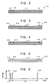
- FIG. 2 is an A-A cross sectional view of the recording medium 10 in FIG. 1 .
- the first line segments 12 / 13 and the second line segment 14 are concave portions formed on the recording surface 11.
- the recording layer of the recording medium 10 is formed by using the polymer material, such as PMMA
- the first line segments 12 / 13 and the second line segment 14 can be formed by irradiating laser light onto the recording surface 11 and displacing it linearly.
- the first line segments 12 / 13 and the second line segment 14 are straight lines, so that it is possible to form them easily by using the laser light in this manner.
- first line segments 12 / 13 and the second line segment 14 shown in FIG. 2 are just one example.
- Other physical features of the first line segments 12/13 and the second line segment 14, such as the shapes of the cross sectional surfaces, are not specially limited if they are different from those of the other part on the recording surface 11.
- first line segments 22 and 23 and a second line segment 24 onto a recording surface 21 are convex-shaped cross sectional surfaces.
- first line segments 32 and 33 and a second line segment 34 onto a recording surface 31 by making a crystal structure of a material, which forms the recording layer, different from those of the other part.
- the recoding layer is formed from the phase change material, only part corresponding to the first line segments 32 and 33 and the second line segment 34 are formed in an amorphous phase.
- the recording layer is the ferroelectric material, it is possible to form first line segments 42 and 43 and a second line segment 44 onto a recording surface 41 by making a polarization direction of the ferroelectric material different from those of the other part.
- the principle of recognizing a position on the recording surface 11 on the basis of the first line segments 12 / 13 and the second line segment 14 is as follows.
- FIG. 1 at first, it is assumed that the head of the recording apparatus is displaced from P1 to P2 at a predetermined speed and scans between P1 and P2.
- a scan line of the head crosses the first line segment 12 at an intersection C1, crosses the first line segment 13 at an intersection C2, and crosses the second line segment 14 at an intersection C3.
- pulse signals S1, S2, and S3 as shown in FIG. 6 are obtained from the head.
- the pulse signal S1 is obtained when the head passes the intersection C1.
- the pulse signal S2 is obtained when the head passes the intersection C2.
- the pulse signal S3 is obtained when the head passes the intersection C3.
- a time length t1 between the pulse signal S1 and the pulse signal S2 corresponds to a distance d1 between the intersection C1 and the intersection C2.
- a time length t2 between the pulse signal S2 and the pulse signal S3 corresponds to a distance d2 between the intersection C2 and the intersection C3. Therefore, by comparing the time length t1 and the time length t2, it is possible to measure or calculate the distance d2 based on the distance d1.
- FIG. 1 it is assumed that the head of the recording apparatus is displaced from P3 to P4 at a predetermined speed and scans between P3 and P4.
- a scan line of the head crosses the first line segment 12 at an intersection C4, crosses the first line segment 13 at an intersection C5, and crosses the second line segment 14 at an intersection C6.
- pulse signals each corresponding to relative one of the intersections C4, C5, and C6, are obtained from the head.
- the distance between the intersections C4 and C5 is the same as the distance between the intersections C1 and C2, i.e. d1.
- the distance d3 between the intersections C5 and C6 is shorter than the distance d2 between the intersections C2 and C3.
- the distance d3 based on the distance d1 is shorter than the distance d2 based on the distance d1.
- a distance between (i) an intersection of the first line segment 13 and a scan line and (ii) an intersection of the second line segment 14 and the scan line varies.
- the highly accurate position recognition can be performed. This is because the distance between the first line segment 12 and the first lien segment 13 is the immovable standard.
- the position of the head in the Y direction shown with the arrow can be recognized, not by measuring or calculating the distance between (i) an intersection of the first line segment 13 and a scan line and (ii) an intersection of the second line segment 14 and the scan line, but by measuring or calculating a distance between (i) an intersection of the first line segment 12 and a scan line and (ii) an intersection of the second line segment 14 and the scan line.
- the fact that the head passes the intersections C1, C2, and C3 is detected as the pulse signals S1, S2, and S3 or the like, and the distance between the intersections is measured or calculated on the basis of the time interval between these pulse signals.
- the method of recognizing the distance between the intersections is not limited to this example. It is possible to adopt various methods, for example, a method of detecting these elements in analog quantity, or the like.
- the first line segments 12 / 13 and second line segment 14 as being the position information are formed in the entire area of the recording surface 11.
- a position recognition area 51A is formed in one portion of a recording surface 51, and that the first line segments 12 / 13 and the second line segment 14 are formed only in the position recognition area 51A.
- the information to be recorded by the recording apparatus is recorded mainly in information recording areas 51B in the recording surface 51.
- the recording surface 51 of the recoding medium 50 is divided into one position recognition area 51A and eight position recognition areas 51B, as shown in FIG.
- a recording medium 60 shown in FIG. 8 it may be constructed such that a plurality of position recognition areas 61A and 61B are formed on a recording surface 61.
- the position recognition in the Y axis direction is performed on the basis of the position information (three line segments in total) formed in the position recognition area 61A.
- the position recognition in the X axis direction is performed on the basis of the position information (three line segments in total) formed in the position recognition area 61B.
- the recording of the information is performed with respect to information recording areas 61C.
- the recording media 10 to 60 as being the first embodiment of the present invention, it is possible to easily form the position information because the position information is constructed from the first line segments 12 / 13 and the second line segment 14. Even if the recording density of the information increases and the track pitch extremely decreases, easiness of the formation of the first line segments 12 / 13 and the second line segment 14 hardly changes. Therefore, even if the recording density of the data increases, it is possible to accurately recognize a position on the recording surface 11. Moreover, because the position information is easily formed, it is possible to reduce a format time length for the recording medium 10.
- the first line segments 12 / 13, which are parallel to each other, are formed on the recording surface 11, so that it is possible to measure or calculate the distance between (i) the first line segment 12 or 13 and a scan line and (ii) the second line segment 14 and the scan line, on the basis of the distance d1 between (i) an intersection of the first line segment 12 and a scan line and (ii) an intersection of the first line segment 13 and the scan line.
- the distance d1 between (i) an intersection of the first line segment 12 and a scan line and (ii) an intersection of the first line segment 13 and the scan line.
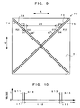
- FIG. 9 shows the second embodiment of the recording medium of the present invention.
- the application, material, outer shape, and size of a recording medium 70 shown in FIG. 9 are substantially the same as those of the recording medium 10 shown in FIG. 1 , and matters in these points, which are not limited at least in the recording medium 10, are not limited in the recording medium 70, either.
- the recording medium 70 has a recording surface 71, and on the recording surface 71, position information for recognizing a position on the recording surface 71 is recorded.
- the position information includes first line segments 72 / 73 and second line segments 74 / 75.
- the first line segments 72 and 73 are formed by giving physical features which are different from those of the other part on the recording surface 71.
- the number of the first line segments 72 and 73 is two.
- the first line segments 72 and 73 are disposed parallel to each other.
- the first line segments 72 and 73 are also disposed to be adjacent each other.
- the first line segments 72 and 73 shown in FIG. 9 are just an example, except that they are parallel to each other.
- the number of the first line segments may be equal to or greater than two. With respect to the position relationship between the first line segments 72 and 73, the first line segments 72 and 73 are not necessarily adjacent each other if parallel to each other.
- first line segments 72 and 73 With respect to the first line segments 72 and 73, their upper ends are placed in the vicinity of the upper left end of the recording surface 71, and their lower ends are placed in the vicinity of the lower right end of the recording surface 71.
- the first line segments 72 and 73 extend straight from the vicinity of the upper left end to the vicinity of the lower right end of the recording surface 71.
- the positions of the end portions of the first line segments 72 and 73 and the lengths thereof are not limited to this example.
- the widths of the first line segments 72 and 73 are not limited, either.
- the second line segments 74 and 75 are formed by giving physical features which are different from those of the other part on the recording surface 71.
- the number of the second line segments is two.
- the second line segments 74 and 75 are disposed parallel to each other.
- the second line segments 74 and 75 are also disposed to be adjacent each other.
- the second line segments 74 and 75 shown in FIG. 9 are just an example, except that they are parallel to each other.
- the number of the second line segments may be two or more. With respect to the position relationship between the second line segments 74 and 75, the second line segments 74 and 75 are not necessarily adjacent each other, if parallel to each other.
- the second line segments 74 and 75 With respect to the second line segments 74 and 75, their upper ends are placed in the vicinity of the upper right end of the recording surface 71, and their lower ends are placed in the vicinity of the lower left end of the recording surface 71.
- the second line segments 74 and 75 extend straight from the vicinity of the upper right end to the vicinity of the lower left end of the recording surface 71.
- the positions of the end portions of the second line segments 74 and 75 and the lengths thereof are not limited to this example.
- the widths of the second line segments 74 and 75 are not limited, either.
- the first line segments 72 / 73 and the second line segments 74 / 75 are disposed to cross each other on the recording surface 71. More specifically, the first line segments 72 / 73 and the second line segments 74 / 75 cross substantially in the center of the recoding surface 71. An angle at which the first line segments 72 / 73 and the second line segments 74 / 75 cross is 90 degrees. Incidentally, the interval between the first line segments 72 and 73 is equal to the interval between the second line segments 74 and 75. Incidentally, it is not necessary to dispose the first line segments 72 / 73 and the second line segments 74 / 75 to cross each other on the recording surface 71.
- first line segments 72 / 73 and the second line segments 74 / 75 may be disposed such that at least one of the first line segments 72 / 73 or an extension line of at least one of the first line segments 72 / 73 crosses at least one of the second line segments 74 / 75 or an extension line of at least one of the second line segments 74 and 75.
- the angle at which the first line segments 72 / 73 or the extension lines of the first line segments 72 / 73 cross the second line segments 74 / 75 or the extension lines of the second line segments 74 / 75 is not limited, either.
- the angle at which the first line segments 72 / 73 or the extension lines of the first line segments 72 / 73 cross the second line segments 74 / 75 or the extension lines of the second line segments 74 / 75 is 90 degrees and where the intersections are disposed in the center of the recording surface 71, even if the recording medium 70 is rotated at 90 degrees on the recording surface 71, the arrangement of the first line segments 72 / 73 and the second line segments 74 / 75 is the same, which is advantageous.
- the first line segments 72 and 73 are desirably at +45 degrees to a prearranged scan direction for recording or reading the information with respect to the recording surface 71 (i.e. a scan direction of the head when the recording medium has a correct position relationship with the head of the recording apparatus, e.g. a straight line between P11 and P12 in FIG. 9 ).
- the second line segments 74 and 75 are desirably at -45 degrees to the prearranged scan line.
- the angle of the first line segments 72 and 73 to the prearranged scan direction is equal to the angle of the second line segments 74 and 75 to the prearranged scan line, by which it is possible to accurately recognize a position on the recording surface even if the position relationship between the recording medium 71 and the head of the recording apparatus are misaligned. This will be described later.
- each line segment e.g. whether it is concave, whether it is an amorphous phase, or the like
- the recording layer of the recording medium is the polymer material, such as PMMA, it is possible to easily form each line segment by emitting laser light onto the recording surface and displacing it linearly.
- the principle of recognizing a position on the recording surface 71 on the basis of the first line segments 72 / 73 and the second line segments 74 / 75 is as follows.
- FIG. 9 at first, it is assumed that the head of the recording apparatus is displaced from P11 to P12 at a predetermined speed and scans between P11 and P12.
- a scan line of the head crosses the first line segment 72 at an intersection C11, crosses the first line segment 73 at an intersection C12, crosses the second line segment 74 at an intersection C13, and crosses the second line segment 75 at an intersection C14.
- pulse signals S11, S12, S13, and S14 as shown in FIG. 10 are obtained from the head.
- the pulse signal S11 is obtained when the head passes the intersection C11.
- the pulse signal S12 is obtained when the head passes the intersection C12.
- the pulse signal S13 is obtained when the head passes the intersection C13.
- the pulse signal S14 is obtained when the head passes the intersection C14.
- a time length t11 between the pulse signal S11 and the pulse signal S12 corresponds to a distance d11 between the intersection C11 and the intersection C12.
- a time length t12 between the pulse signal S12 and the pulse signal S13 corresponds to a distance d12 between the intersection C12 and the intersection C13. Therefore, by comparing the time length t11 and the time length t12, it is possible to measure or calculate the distance d12 based on the distance d11.
- a distance between (i) an intersection of the first line segment 73 and a scan line and (ii) an intersection of the second line segment 74 and the scan line varies.
- a distance between (i) an intersection of the first line segment 72 and a scan line and (ii) an intersection of the first line segment 73 and the scan line does not change and is always d11. This is because the first line segment 72 and the first line segment 73 are parallel to each other.
- the highly accurate position recognition can be performed.
- the above-description about the principle of the position recognition is substantially the same as the case of the recording medium 10 shown in FIG. 1 and FIG. 6 .
- the recording medium 70 it is also possible to recognize position misalignment of the recording medium 70.
- the time length t11 between the pulse signals S11 and S12 corresponds to the distance d11 between the intersections C11 and C12.
- the time length t13 between the pulse signals S13 and S14 corresponds to the distance d13 between the intersections C13 and C14.
- the interval between the first line segments 72 and 73 is equal to the interval between the second line segments 74 and 75.
- the actual scan direction of the head deviates from the prearranged scan direction.
- This causes a difference between (i) the absolute value of the angle of the first line segments 72 and 73 to the actual scan direction of the head and (ii) the absolute value of the angle of the second line segments 74 and 75 to the actual scan direction of the head. Due to this, a timing of the head passing the intersection of each line segment and the scan line shifts, and as shown in FIG. 12 , timings of obtaining the pulse signals S11, S12, S13, and S14 change. As a result, there arises a differences between the time length t11 and the time length t13 (t11>t13 in the example in FIG. 12 ).
- the angle between the prearranged scan direction and the actual scan direction of the head (hereinafter referred to as a "mounting-misalignment-angle"), which is generated by the position misalignment of the recording medium 70 caused by the slight rotation, is regarded as ⁇
- the scanning speed of the head is regarded as S
- the time length t11 and the time length t13 can be expressed with the following formulae (1) and (2), respectively.
- the mounting-misalignment-angle ⁇ can be recognized in this manner, it is possible to recognize a position on the recording surface 71 highly accurately, while correcting the misalignment between the recording medium and the head (i.e. a gap between the prearranged scan direction and the actual scan direction), on the basis of the mounting-misalignment-angle ⁇ .
- the correction may be performed by operation processing or by rotating the recording medium 70 by using a rotational mechanism.
- the first line segments 72 / 73 and the second line segments 74 / 75 as being the position information are formed in the entire area of the recording surface 71.
- a position recognition area is formed in one portion of the recording surface 71, and that the first line segments 72 / 73 and the second line segments 74 / 75 are formed only in the position recognition area (refer to FIG. 7 ). It is also possible to form a plurality of position recognition areas on the recording surface 71 (refer to FIG. 8 ).
- the misalignment in the rotational direction of the recording medium 70 is recognized on the basis of the first line segments 72 / 73 and the second line segments 74 / 75 (or a part of the first line segment 72 / 73 and the second line segment 74 / 75) formed in the position recognition area placed in the center of the recording medium 70.
- the recording medium 70 as being the second embodiment of the present invention, it is possible to easily form the position information, as with the recoding medium 10, because the position information is constructed from the first line segments 72 / 73 and the second line segments 74 / 75. Therefore, even if the recording density of the data increases, it is possible to accurately recognize a position on the recording surface 71, and it is possible to reduce a format time length for the recording medium 70. Moreover, since not only the first line segments but also the second line segments are two or more parallel line segments, it is possible to accurately recognize a position on the recording surface 71 even if there is position misalignment between the recording medium 70 and the head of the recording apparatus.
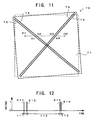
- FIG. 13 shows the third embodiment of the recording medium of the present invention.
- the basic structure of a recording medium 80 shown in FIG. 13 is substantially the same as that of the recording medium 70 shown in FIG. 9 .
- there are two pairs of two mutually parallel first line segments Namely, they are one pair of two first line segments 82 and 83, and another pair of two first line segments 84 and 85.
- there are three pairs of two mutually parallel second line segments Namely, they are one pair of two second line segments 86 and 87, another pair of two second line segments 88 and 89, and further another pair of two second line segments 90 and 91.
- the number of pairs of the first line segments and the number of pairs of the second line segments are not limited to this example.
- the first line segments 82 and 83 and the second line segments 86 and 87 cross at an intersection (intersection area) C21.
- the first line segments 82 and 83 and the second line segments 88 and 89 cross at an intersection (intersection area) C22.
- the first line segments 84 and 85 and the second line segments 88 and 89 cross at an intersection (intersection area) C23.
- the first line segments 84 and 85 and the second line segments 90 and 91 cross at an intersection (intersection area) C24.
- each of the line segments 82 to 91 is disposed such that an arbitrary straight line parallel to a prearranged scan direction of the head (e.g. a straight line between P21 and P22) crosses any one of the first line segments 82 to 85 and any one of the second line segments 86 to 91 in any place except the intersections C21, C22, C23, and C24.
- Such arrangement can be realized by making the absolute value of an angle of the first line segments 82 to 85 to the prearranged scan direction of the head different from the absolute value of an angle of the second line segments 86 to 91 to the prearranged scan direction of the head. By this, it is possible to recognize a position in any place on the recording surface 81.
- a scan line of the head i.e. a straight line between P23 and P24
- a scan line of the head may pass only an intersection C29 and C30 which are made with the first line segments and the second line segments.
- it is impossible to recognize the position of the head on the recording surface because it is impossible to measure or calculate a distance between the first line segment and the second line segment.
- the head scans from P21 to P22, that an intersection of the scan line and the first line segment 82 is C25, that an intersection with the first line segment 83 is C26, an intersection with the second line segment 88 is C27, and an intersection with the second line segment 89 is C28.
- a distance d21 between the intersections C25 and C26 is equal to a distance d22 between the intersections C27 and C28.
- the interval between the first line segments 82 and 83, and the interval between the second line segments 88 and 89 are set to satisfy the above arrangement condition.
- pulse signals S21 to S24 corresponding to the intersections C25 to C28 are obtained, respectively, as shown in FIG. 15 .
- a time length t21 between the pulse signals S21 and S22 is equal to a time length t22 between the pulse signals S23 and S24.
- the interval between the first line segments 84 and 85 is equal to the interval between the first segments 82 and 83.
- the interval between the second line segments 88 and 89 and the interval between the second line segments 90 and 91 are equal to the interval between the second line segments 86 and 87.
- the first line segments 82 to 85 are all disposed parallel to each other.
- the second line segments 86 to 91 are also all disposed parallel to each other. Therefore, in any combination of the first line segments and the second line segments, which cross each other, the above arrangement condition is satisfied.
- the recording medium 80 it is possible to recognize every position on the recording surface 81 highly accurately and easily.
- FIG. 16 shows the fourth embodiment of the recording medium of the present invention.
- the basic structure of a recording medium 100 shown in FIG. 16 is substantially the same as that of the recording medium 70 shown in FIG. 9 .
- first line segments Namely, they are one pair of two first line segments 102 and 103, and another pair of two first line segments 104 and 105.
- second line segments Namely, they are one pair of two second line segments 106 and 107, and another pair of two second line segments 108 and 109.
- first line segments 102 and 103 and the second line segments 106 and 107 their extension lines cross outside the recording surface 101, so that there is not any intersection of these line segments on the recording surface 101.
- FIG. 17 shows the fifth embodiment of the recording medium of the present invention.
- the basic structure of a recording medium 110 shown in FIG. 17 is substantially the same as that of the recording medium 70 shown in FIG. 9 .
- a recording surface 111 of the recording medium 110 is divided into a plurality of zones 111A, and first line segments 112 and 113 and second line segments 114 and 115 are disposed in each zone 111A.
- the first line segments 112 and 113 and the second line segments 114 and 115 are segmentalized into a plurality of line segments in each zone 111A.
- FIG. 18 shows the sixth embodiment of the recording medium of the present invention.
- the basic structure of a recording medium 120 shown in FIG. 18 is substantially the same as that of the recording medium 70 shown in FIG. 9 .
- the third line segments 126 to 130 are formed by giving physical features which are different from those of the other part on the recording surface 121.
- the third line segments 126 and 127 are disposed parallel to the first line segments 122 and 123.
- the third line segments 128 to 130 are disposed parallel to the second line segments 124 and 125.
- An interval between the third line segments which are adjacent to each other may be different for each line segment pair.
- the interval between the third line segments which are adjacent to each other may be different between (i) a group of the first line segments 122 and 123 and the third line segments 126 and 127 and (ii) a group of the second line segments 124 and 125 and the third line segments 128, 129, and 130.
- An interval between the first line segment and the third line segment (e.g. the interval between the first line segment 123 and the third line segment 126, or the like) may be different for each line segment pair. If there are a plurality of position recognition areas on the recording surface 121, an interval between these may be different in each position recognition area.
- the number of the third line segments may be different for each line segment pair or in each position recognition area.
- the interval or the number of the third line segments, or the like it is possible to distinguish a particular group from among a plurality of groups of the line segments.
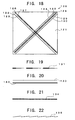
- FIG. 19 to FIG. 23 show various aspects of the line segment to be formed on the recording surface of the recording medium of the present invention.
- FIG. 19 it is possible to vary the width of a line segment 131 according to a predetermined rule. By this, it is possible to give the address information to the width of the line segment 131.
- FIG. 20 it is possible to thicken a line segment 132 as a whole and to thin a line segment 133 as a whole.
- the width of the line segment may be changed for each line segment group or in each position recognition area. By this, it is possible to give the address information to the width of the line segment.
- a line segment 135 As shown in FIG. 22 , it is also possible to form a line segment 135 as a whole by arranging a plurality of relatively shorter (or divided) line segments linearly. For example, if it is difficult to form a completely straight line on the recording surface for reasons of a crystal structure or the like, it is possible to form such shorter line segments that do not go against the crystal structure and arrange them linearly. Even in this case, if an interval between the short line segments or the like is made smaller than the reading resolution of the head, the arrangement of the shorter line segments is substantially equivalent to a line segment.
- the line segments formed on the recording medium are used as the position information.
- PLL Phase Lock Loop
- FIG. 23 shows the first embodiment of the position recognition apparatus of the present invention.
- a position recognition apparatus 140 shown in FIG. 23 is intended to recognize a position on a recording surface of a recording medium provided with: at least two first line segments, which are parallel to each other, formed by giving physical features which are different from those of other part on the recording surface; and at least one second line segment formed by giving physical features which are different from those of other part on the recording surface, the first line segments and the second line segment being disposed such that at least one of the first line segments or an extension line of at least one of the first line segments crosses the second line segment or an extension line of the second line segment.
- the position recognition apparatus 140 is a preferable apparatus for recognizing a position on the recording surface 11 of the recording medium 10 shown in FIG. 1 , for example.
- the explanation below is about the case where a position on the recording surface 11 of the recording medium 10 is recognized by the position recognition apparatus 140.
- the position recognition apparatus 140 is provided with: a detecting device 141; a first distance recognition device 142; a second distance recognition device 143; and a comparing device 144.
- the detecting device 141 scans, by using a head 141A, for example, on a scan line, which crosses the first line segments 12 / 13 and the second line segment 14, to thereby detect the intersection of the first line segment 12 and the scan line, the intersection of the first line segment 13 and the scan line, and the intersection of the second line segment 14 and the scan line.
- the detecting device 141 detects the intersections C1, C2, and C3 by the head scanning from P1 to P2 in FIG. 1 , and outputs the result as the pulse signals S1, S2, and S3 in FIG. 6 .
- the first distance recognition device 142 recognizes a distance between (i) the intersection of the first line segment 12 and the scan line and (ii) the intersection of the first line segment 13 and the scan line, on the basis of a detection result of the detecting device 141.
- the first distance recognition device 142 can be realized with a counter, for example. In this case, for example, the first distance recognition device 142 recognizes the distance d1 between the intersection C1 and the intersection C2, by counting the time length t1 between the pulse signal S1 and the pulse signal S2 with the counter.
- the second distance recognition device 143 recognizes a distance between (i) the intersection of the first line segment 13 and the scan line and (ii) the intersection of the second line segment 14 and the scan line, on the basis of the detection result of the detecting device 141.
- the second distance recognition device 143 can be realized with a counter, for example. In this case, for example, the second distance recognition device 143 recognizes the distance d2 between the intersection C2 and the intersection C3, by counting the time length t2 between the pulse signal S2 and the pulse signal S3 with the counter.
- the comparing device 144 compares the distance recognized by the first distance recognition device 142 with the distance recognized by the second distance recognition device 143. By this, it is possible to measure or calculate the distance between (i) the intersection of the first line segment 13 and the scan line and (ii) the intersection of the second line segment 14 and the scan line, on the basis of the distance between (i) the intersection of the first line segment 12 and the scan line and (ii) the intersection of the first line segment 13 and the scan line. Then, by the above-described principle of the position recognition, it is possible to recognize the position of the head in the Y direction shown with the arrow.
- the second distance recognition device 143 it is possible to recognize, not the distance between (i) the intersection of the first line segment 13 and the scan line and (ii) the intersection of the second line segment 14 and the scan line, but the distance between (i) the intersection of the first line segment 12 and the scan line and (ii) the intersection of the second line segment 14 and the scan line.
- the comparing device 144 it is also possible to measure or calculate the distance between (i) the intersection of the first line segment 12 and the scan line and (ii) the intersection of the second line segment 14 and the scan line, on the basis of the distance between (i) the intersection of the first line segment 12 and the scan line and (ii) the intersection of the first line segment 13 and the scan line.
- the position recognition apparatus 140 may be realized as an exclusive apparatus, but can be also realized by making a computer program, which realizes a position recognition method as described later, and by making a computer read this program.
- the position recognition method is intended to recognize a position on a recording surface of a recording medium provided with: at least two first line segments, which are parallel to each other, formed by giving physical features which are different from those of other part on the recording surface; and at least one second line segment formed by giving physical features which are different from those of other part on the recording surface, the first line segments and the second line segment being disposed such that at least one of the first line segments or an extension line of at least one of the first line segments crosses the second line segment or an extension line of the second line segment.
- the position recognition method is provided with: a detecting process of scanning on a scan line, which crosses the first line segments and the second line segment, to thereby detect an intersection of one of the first line segments and the scan line, an intersection of another of the first line segments and the scan line, and an intersection of the second line segment and the scan line; a first distance recognition process of recognizing a distance between (i) the intersection of one of the first line segments and the scan line and (ii) the intersection of another of the first line segments and the scan line, on the basis of a detection result of the detecting process; a second distance recognition process of recognizing a distance between (i) the intersection of one or another of the first line segments and the scan line and (ii) the intersection of the second line segment and the scan line, on the basis of the detection result of the detecting process; and a comparing process of comparing the distance recognized by the first distance recognition process with the distance recognized by the second distance recognition process.
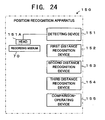
- FIG. 24 shows the second embodiment of the position recognition apparatus of the present invention.
- a position recognition apparatus 150 shown in FIG. 24 is intended to recognize a position on a recording surface of a recording medium provided with: at least two first line segments, which are parallel to each other, formed by giving physical features which are different from those of other part on the recording surface; and at least two second line segments, which are parallel to each other, formed by giving physical features which are different from those of other part on the recording surface, the first line segments and the second line segments being disposed such that at least one of the first line segments or an extension line of at least one of the first line segments crosses at least one of the second line segments or an extension line of at least one of the second line segments.
- the position recognition information 150 is a preferable apparatus for recognizing a position on the recording surface 71 of the recording medium 70 shown in FIG. 9 , for example.
- the explanation below is about the case where a position on the recording surface 71 of the recording medium 70 is recognized by the position recognition apparatus 150.
- the position recognition apparatus 150 is provided with: a detecting device 151; a first distance recognition device 152; a second distance recognition device 153; a third distance recognition device 154; and a comparison-operating device 155.
- the detecting device 151 scans, by using a head 151A, for example, on a scan line, which crosses the first line segments 72 / 73 and the second line segments 74 / 75, to thereby detect the intersection of the first line segment 72 and the scan line, the intersection of the first line segment 73 and the scan line, the intersection of the second line segment 74 and the scan line, and the intersection of the second line segment 75 and the scan line.
- the detecting device 151 detects the intersections C11, C12, C13, and C14 by the head scanning from P11 to P12 in FIG. 9 , and outputs the result as the pulse signals S11, S12, S13, and S14 in FIG. 10 .
- the first distance recognition device 152 recognizes a distance between (i) the intersection of the first line segment 72 and the scan line and (ii) the intersection of the first line segment 73 and the scan line, on the basis of a detection result of the detecting device 151.
- the first distance recognition device 152 can be realized with a counter, for example. In this case, for example, the first distance recognition device 152 recognizes the distance d11 between the intersection C11 and the intersection C12, by counting the time length t11 between the pulse signal S11 and the pulse signal S12 with the counter.
- the second distance recognition device 153 recognizes a distance between (i) the intersection of the second line segment 74 and the scan line and (ii) the intersection of the second line segment 75 and the scan line, on the basis of the detection result of the detecting device 151.
- the second distance recognition device 153 can be realized with a counter, for example. In this case, for example, the second distance recognition device 153 recognizes the distance d13 between the intersection C13 and the intersection C14, by counting the time length t13 between the pulse signal S13 and the pulse signal S14 with the counter.
- the third distance recognition device 154 recognizes a distance between (i) the intersection of the first line segment 73 and the scan line and (ii) the intersection of the second line segment 74 and the scan line, on the basis of the detection result of the detecting device 151.
- the third distance recognition device 154 can be realized with a counter, for example. In this case, for example, the third distance recognition device 154 recognizes the distance d12 between the intersection C12 and the intersection C13, by counting the time length t12 between the pulse signal S12 and the pulse signal S13 with the counter.
- the comparison-operating device 155 performs comparison operation by using the distance recognized by the first distance recognition device 152, the distance recognized by the second distance recognition device 153, and the distance recognized by the third distance recognition device 154. For example, by comparing the distance recognized by the first distance recognition device 152 with the distance recognized by the third distance recognition device 154, it is possible to recognize the position of the head in the Y direction shown with the arrow (refer to FIG. 9 ), on the basis of the above-described principle of the position recognition.
- the position recognition apparatus 150 may be realized as an exclusive apparatus, but can be also realized by making a computer program, which realizes a position recognition method as described later, and by making a computer read this program.
- the position recognition method is intended to recognize a position on a recording surface of a recording medium provided with: at least two first line segments, which are parallel to each other, formed by giving physical features which are different from those of other part on the recording surface; and at least two second line segments, which are parallel to each other, formed by giving physical features which are different from those of other part on the recording surface, the first line segments and the second line segments being disposed such that at least one of the first line segments or an extension line of at least one of the first line segments crosses at least one of the second line segments or an extension line of at least one of the second line segments.
- the position recognition method is provided with: a detecting process of scanning on a scan line, which crosses the first line segments and the second line segments, to thereby detect an intersection of one of the first line segments and the scan line, an intersection of another of the first line segments and the scan line, an intersection of one of the second line segments and the scan line, and an intersection of another of the second line segments and the scan line; a first distance recognition process of recognizing a distance between (i) the intersection of one of the first line segments and the scan line and (ii) the intersection of another of the first line segments and the scan line, on the basis of a detection result of the detecting process; a second distance recognition process of recognizing a distance between (i) the intersection of one of the second line segments and the scan line and (ii) the intersection of another of the second line segments and the scan line, on the basis of the detection result of the detecting process; a third distance recognition process of recognizing a distance between (i) the intersection of one or another of the first line segments and the scan line and (ii) the
- the present invention is applied to an information recording / reproducing apparatus for performing thermomechanical recording of information onto a recording medium by using a cantilever array and reading and reproducing the information recorded on the recording medium.
- This is a preferable one example to implement the prevent invention.
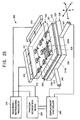
- FIG. 25 shows a recording / reproducing apparatus 200 in the example of the present invention.
- the recording / reproducing apparatus 200 is provided with: a head 210; a recording medium 220; an X-Y-Z stage 230; a recording / reproducing processor 241; a position recognition device 244; and a displacement controller 245.
- the head 210 is provided with a support portion 211 and cantilevers 212. Specifically, the cantilevers 212 are supported on the bottom surface of the support portion 211.
- the support portion 211 is constructed from a substrate of a silicon compound, glass, metal, or the like.
- the support portion 211 is disposed above a recording surface of the recording medium 220.
- the support portion 211 is drawn in perspective.
- the support portion 211 is usually not transparent, although it can be, depending on the selection of the material.
- the cantilevers 212 are formed from high-doped silicon. Each cantilever 212 is provided with an arm and a needle. The arm has elasticity and can be bent. The base end portion of the arm is supported by the support portion 211, and the needle is disposed on the other end portion of the arm. A tip diameter of the needle is several nanometers to several tens nanometers. The total number of the cantilevers 212 is nine, and the cantilevers 212 are arranged in a matrix of 3 ⁇ 3 on the support portion 211. Out of the cantilevers 212, a cantilever disposed in the center of the support portion 211 is a cantilever exclusive for position recognition (hereinafter referred to as a "position recognition cantilever 212A").
- position recognition cantilever 212A a cantilever exclusive for position recognition
- the total number of the cantilevers 212 is nine, but in practice, it is several tens to several hundreds.
- these cantilevers may include a plurality of cantilevers exclusive for position recognition.
- the recording medium 220 has a square outer shape and a plate shape.
- the recording medium 220 is provided with: a first polymer layer 221; a second polymer layer 222; and a silicon substrate 223.
- the first polymer layer 221 is to record therein information.
- the first polymer layer 221 is formed on the second polymer layer 222 which is formed on the silicon layer 223.
- the material of the first polymer layer 221 is PMMA, for example.
- the second polymer layer 222 is to prevent abrasion at the needle tip caused by the collision of the cantilever 212 and the recording medium 220 when the needle tip of the cantilever 212 is pressed onto the recording medium 220 in recording the information.
- the second polymer 222 is formed between the first polymer layer 221 and the silicon substrate 223.
- the material of the second polymer layer 222 is closslinked photoresist, for example.
- the silicon substrate 223 is formed from a silicon material which is excellent in heat conduction and heat radiation or release.
- the silicon substrate 223 supports the first polymer layer 221 and the second polymer layer 222, and the silicon substrate 223 has a function for driving the head radiation in recording.
- the recording medium 220 has a recording surface 224 to record thereon the information.
- Nine divisional areas 225 are formed on the recording surface 224, and the divisional areas 225 are disposed in a matrix of 3 ⁇ 3.
- Each of the divisional areas 225 corresponds to relative one of the nine cantilevers 212, and the relative one of the nine cantilevers 212 is displaced in the range of the corresponding divisional area 225.
- Out of the divisional areas 225 one divisional area placed in the center is an area exclusive for position recognition (hereinafter referred to as a "position recognition area 225A").
- the position recognition area 225A corresponds to the position recognition cantilever 212A.
- Position information for recognizing a position on the recording surface 224 is formed in the position recognition area 225A. The position information will be described later.
- the X-Y-Z stage 230 displaces the recording medium 220 mounted thereon, in an X direction, in a Y direction, and in a Z direction meeting at right angles to an X-Y plane.
- the recording / reproducing processor 241 is provided with an operation processing circuit, a memory circuit, or the like.
- the recording / reproducing processor 241 is electrically connected to the cantilevers 212 through multiplexers 242 and 243.
- the recording / reproducing processor 241 supplies, to the cantilevers 212, an electrical signal corresponding to the information to be recorded onto the recording medium 220.
- the recording / reproducing processor 241 receives the information (a detection signal) read by using the cantilevers 212 and performs a reproduction process of the information.
- the position recognition device 244 is electrically connected to the cantilevers 212 through the multiplexers 242 and 243.
- the position recognition device 244 receives the position information read by using the position recognition cantilever 212A and recognizes a position on the recording surface 224. Moreover, the position recognition device 244 generates a tracking error signal on the basis of a result of the position recognition, and supplies this signal to the displacement controller 245.
- the specific structure and operation of the position recognition device 244 will be described later.
- the displacement controller 245 is provided with an operation processing circuit, a memory circuit, or the like.
- the displacement controller 245 is electrically connected to the position recognition device 244, and information can be exchanged between the both.
- the displacement controller 245 is connected to the X-Y-Z stage 230 through actuators 246 and 247.
- the displacement controller 245 controls the X-Y-Z stage 230 on the basis of a seek command signal and a jump command signal or the like, which are supplied from the exterior, and displaces the recording medium 220 in an X-Y direction, to thereby displace the cantilevers 212 in the divisional areas 225 to desired positions.
- the displacement controller 245 controls the X-Y-Z stage 230 on the basis of the tracking error signal supplied from the position recognition device 244, to thereby perform tracking control. Furthermore, at the start of the information record or information reproduction, the displacement controller 245 controls the X-Y-Z stage 230 to displace the recording medium 220 in the Z direction so that the needle tip of each cantilever 212 is in contact with the recording surface 224 of the recording medium 220.
- An information recording operation on the recording / reproducing apparatus 200 is as follows.
- the displacement controller 245 displaces the recording medium 220 in the X-Y direction to relatively displace the cantilevers 212 to record-start-positions.
- the displacement controller 245 displaces the recording medium 220 in the Z direction so that the needle tip of each cantilever 212 is in contact with the recording surface 224 of the recording medium 220.
- the needle of the cantilever 212 is pushed by the recording surface, and a force is applied to the end portion of the arm of the cantilever 212 through the needle.
- the arm is slightly bent.
- the recording / reproducing processor 241 supplies an electrical signal corresponding to the information to be recorded to the cantilevers 212.
- the needle of each cantilever 212 has heat of about 400 degree C, for example, so that the first polymer layer 221 under the needle softens. Then, by the elastic force of the arm, the needle tip goes into the first polymer layer 221, to thereby form a pit (a hole or a concave portion) in the first polymer layer 221. Then, the displacement controller 245 displaces the recording medium 220 to a next record position, and the recording / reproducing processors 241 forms a pit corresponding to the information to be recorded next.
- an information reproducing operation on the recording / reproducing apparatus 200 is as follows.
- the displacement controller 245 displaces the recording medium 220 in the X-Y direction to displace the cantilevers 212 to read-start-positions.
- the displacement controller 245 displaces the recording medium 220 in the Z direction so that the needle tip of each cantilever 212 is in contact with the recording surface 224 of the recording medium 220.
- the needle of the cantilever 212 is pushed by the recording surface, and a force is applied to the end portion of the arm of the cantilever 212 through the needle.
- the arm is slightly bent.
- the displacement controller 245 displaces the recording medium 220 in the X-Y direction.
- the information is recorded as the pit in each divisional area 225. If the cantilever 212 is displaced onto the pit by the displacement of the recording medium 220 in the X-Y direction, the needle of the cantilever 212 goes into the pit. As a result, the extent of the bend deformation of the arm becomes mild. The change in the bend of the arm is detected by a piezoelectric element as a detection signal, and the detection signal is supplied to the recording / reproducing processor 241. Then, the recording / reproducing processor 241 extracts the information from the detection signal and reproduces it.
- FIG. 26 shows the recording surface 224 of the recording medium 220.
- the position information is formed in the position recognition area 225A placed in the center of the recording surface 224.
- the position information is the same as the position information formed on the recording surface 71 of the recording medium 70 in FIG. 9 .
- the position information is constructed from the first line segments 72 and 73, which are parallel to each other, and the second line segments 74 and 75, which are parallel to each other.
- the first line segments 72 and 73 cross the second line segments 74 and 75 at 90 degrees in the center of the position recognition area 225A.
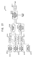
- FIG. 27 shows a specific inner structure of the position recognition device 244.
- two pairs of position recognition circuits 250 as shown in FIG. 27 are disposed.
- One of the position recognition circuits 250 recognizes a position in the X axis direction on the recording surface 224 and generates a tracking error signal in the X axis direction.
- the other position recognition circuit 250 recognizes a position in the Y axis direction on the recording surface 224 and generates a tracking error signal in the Y axis direction.
- the position recognition circuit 250 is provided with: pulse generation circuits 251, 252, and 253; a clock oscillator 254; counters 255, 256, and 257; a comparison circuit 258; a mounting-misalignment detection circuit 259; a tracking error signal generation circuit 260; and a Digital-Analog (D/A) converter 261.
- the operation of the position recognition circuit 250 will be explained hereinafter. Incidentally, the explanation for the operation of the position recognition circuit 250 uses FIG. 27 , FIG. 9, and FIG. 10 .
- the needle tip of the position recognition cantilever 212A is relatively displaced from P11 to P12 on the recording surface and scans on the scan line P11 to P12.
- a detection signal including the pulse signals S11 to S14 as shown in FIG. 10 is outputted from the position recognition cantilever 212A.
- the detection signal is inputted to the pulse generation circuit 251 in FIG. 27 and subsequently supplied from the pulse generation circuit 251 to the pulse generation circuit 252, and to the pulse generation circuit 253.
- the pulse generation circuit 251 extracts the pulse signals S11 and S12 from the detection signal, and supplied the pulse signals S11 and S12 to the counter 255.
- the counter 255 counts on the basis of a reference clock supplied from the clock oscillator 254.
- the counter 255 counts the number of clocks included in the pulse interval of the pulse signals S11 and S12, and outputs the count value to the comparison circuit 258 and the mounting-misalignment detection circuit 259 separately.
- the counter value corresponds to the time length t11 in FIG. 10 , and further corresponds to the distance d11 between the intersection C11 and the intersection C12 in FIG. 9 .
- the pulse generation circuit 252 extracts the pulse signals S12 and S13 from the detection signal, and supplied the pulse signals S12 and S13 to the counter 256.
- the counter 256 also counts on the basis of the reference clock supplied from the clock oscillator 254.
- the counter 256 counts the number of clocks included in the pulse interval of the pulse signals S12 and S13, and outputs the count value to the comparison circuit 258.
- the counter value corresponds to the time length t12 in FIG. 10 , and further corresponds to the distance d12 between the intersection C12 and the intersection C13 in FIG. 9 .
- the pulse generation circuit 253 extracts the pulse signals S13 and S14 from the detection signal, and supplied the pulse signals S13 and S14 to the counter 257.
- the counter 257 also counts on the basis of the reference clock supplied from the clock oscillator 254.
- the counter 257 counts the number of clocks included in the pulse interval of the pulse signals S13 and S14, and outputs the count value to the mounting-misalignment detection circuit 259.
- the counter value corresponds to the time length t13 in FIG. 10 , and further corresponds to the distance d13 between the intersection C13 and the intersection C14 in FIG. 9 .
- the comparison circuit 258 compares the counter value outputted from the counter 255 with the counter value outputted from the counter 256, to thereby measure or calculate the distance d12 by a unit of the distance d11. Specifically, the counter value outputted from the counter 256 is divided by the counter value outputted from the counter 255. A value calculated in this manner indicates a position of the head 210 in the X axis direction or in the Y axis direction on the recording surface 224 (refer to the above-described principle of the position recognition). This value is outputted to the tracking error signal generation circuit 260.
- the mounting-misalignment detection circuit 259 performs an operation based on the above-described formulae (1) and (2) by using the count value outputted from the counter 255 and the count value outputted from the counter 257, to thereby calculate the mounting-misalignment-angle ⁇ .
- a value for indicating the mounting-misalignment-angle ⁇ is outputted to the tracking error signal generation circuit 260.
- the tracking error signal generation circuit 260 generates a tracking error signal for indicating a deflection amount from a desired track position, on the basis of a desired value of the desired track position, the output of the comparison circuit 258 (the value for indicating the position of the head 210), and the output of the mounting-misalignment detection circuit 259 (the mounting-misalignment-angle ⁇ ).
- the D/A converter 261 samples and holds the tracking error signal outputted from the tracking error signal generation circuit 260, to thereby convert it to an analog quantity.
- the tracking error signal which is converted to the analog quantity, is supplied to the displacement controller 245. Then, the tracking error signal is used for the tracking control by the displacement controller 245.
- the position information is read by the position recognition cantilever 212A.
- a reading device for reading the position information may be constructed to be not only the cantilever, but also a reading device which uses magnetism, or a reading device which uses light.
Description
- The present invention relates to a recording medium having a recording surface to record information thereon and having a position recognition structure for recognizing a position on the recording surface, a position recognition apparatus for recognizing the position on the recording surface, and a position recognition method.
- As large-capacity recording media used for various apparatuses, such as a computer, a player and a recorder for music and video or the like, and a car navigation apparatus, there are a compact disc, a DVD, a hard disc and the like. With respect to any one of the recording media, it is possible to record a huge amount of information onto a recording surface formed on the disc at high density.
- In such large-capacity recording media, it is required to accurately recognize a recording position of the information on the recording surface. It is also required to set a rule about the recording position and arrangement of the information, and it is required to record and read the information highly accurately according to the rule.
- In response to the requirement, for example, in a currently used DVD-RAM, a land-groove method is adopted as its recording method. Namely, on the recording surface, grooves are formed in the circumferential direction. The information is recorded onto the grooves and onto the lands (i.e. a place between the grooves). By this, the information is defined by the grooves, and arranged and recorded in the circumferential direction of the disc. The lines of the information arranged in the circumferential direction of the disc in this manner correspond to tracks. Moreover, each track is divided at predetermined intervals in the circumferential direction of the disc. The divisional small areas correspond to sectors. In each of the sectors, address pits having a bumpy shape are formed. Moreover, a wobble having a predetermined cycle is formed on the groove, which is formed on the recording surface, and on the basis of the cycle of the wobble, it is possible to estimate a position of the address pit.
- In the DVD-RAM having the recording method as described above, it is possible to accurately recognize the record position of the information, and it is possible to record and read the information highly accurately. This is because the groove formed on the recording surface is an absolute (or immovable) standard for the position recognition.
- Recently, the following method has been developed: i.e., a method of recording the information onto the recording medium by using a sub-micro-scale or nano-scale cantilever or probe or the like. Such a recording method includes: a method of recording the information by using spontaneous polarization of a ferroelectric substance; a method of recording the information by making a hole on a polymer film with heat; a method of recording the information by using charge accumulation of a laminated material, which is provided with an silicon oxide film and/or a silicon nitride film, etc., or the like. Moreover, a method of reproducing the information recorded on the recording medium by the recording method has been also developed. Such a reproducing method includes: a method of using a technique of Scanning Nonlinear Dielectric Microscopy (SNDM), a method of using a technique of Scanning Maxwell-stress Microscopy, a method of using a technique of Kelvin Force Microscopy, a method of using a technique of Scanning Capacitance Microscopy, or the like.
- According to the recording method and the reproducing method, it is possible to record the information onto the recording medium at super high density, and read and reproduce the recorded information at high resolution. The recording density or reading resolution is beyond the limitation of magnetic recording and optical recording. For example, a track pitch of the DVD-RAM is 0.74µm, but according to the information recording / reproducing method by using the prove or the like, it is possible to reduce the track pitch to 30nm or less, for example.
- However, if the recording density increases, the track pitch decreases. As a result, it is difficult to form the groove in association with the track on the recording surface of the recording medium. If there is not any groove on the recording surface, it is extremely difficult to accurately recognize the recording position of the information as there is no absolute (or immovable) standard to recognize the recording position of the information.
- Even if there is not any groove, the following method is also conceivable: i.e., a method of forming the address pits or sector marks at predetermined intervals on the recording surface, to thereby recognize the recording position of the information on the basis of the address pits or sector marks. However, if the recording density is a super high density, it is difficult even to form the address pits or sector marks at predetermine intervals without any standard. Like the groove in the DVD-RAM, it is desirable to form a clear and absolute standard on the recording surface of the recording medium.
- Moreover, the following position recognition method is also conceivable: i.e., a method of recognizing the recording position of the information by a positioning mechanism for supporting the recording medium itself, such as a stage, or by a positioning mechanism for recording the information, such as a head, without depending on a physical mark or a locus formed on the recording surface of the recording medium, such as the groove. However, it is unrealistic to realize the highly accurate nano-scale position recognition by the supporting structure of the recording medium and by the positioning mechanism of the head. For example, if the position of the recording medium mounted on the stage is misaligned even slightly, then, it is no longer capable of accurately recognizing the recording position of the information. Again, it is desirable that there is the absolute (or immovable) standard on the recording surface of the recording medium.
- Moreover, in the case of a disc-shaped recording medium, such as the DVD-RAM, even if the recording density of the information increases, it may not be impossible to form the grooves onto the recording surface if the accuracy is relaxed to some extent. This is because in the case of the disc-shaped recording medium, once its rotational axis is determined, it is relatively easy to form the grooves, which are spiral-shaped, onto the recording surface. However, in the case of the recording medium in which the information is scheduled to be arranged and recorded in a matrix form on the recording surface, it is required to form the tracks to extend on straight lines in its X axis direction or Y axis direction. In this case, it is extremely difficult to form the grooves which extend on straight lines in the X axis direction or Y axis direction, as compared to the case of forming the spiral groove.
- On the other hand, if the grooves can be formed at extremely small intervals onto the recording surface, it takes a long time to form the grooves because the number of grooves is huge. As a result, it takes a long time to produce or manufacture the recording medium or format the recording medium. This is disadvantageous.
- Furthermore, if the grooves can be formed at extremely small intervals onto the recording surface, as a result of this, the directions of the tracks are determined from these grooves. Thus, in mounting the recording medium onto a recording apparatus, even slight position misalignment is not allowed between the recording medium and a probe head of the recording apparatus. This is because it is difficult to perform accurate tracking if the positions of the recording medium and the probe head of the recording apparatus are misaligned even slightly, as the directions of a huge number of tracks are determined in advance in the extremely small track pitches. This is a big hindrance to the design and production of the recording apparatus.
- It is therefore a first object of the present invention to provide a recording medium having a position recognition structure capable of accurately recognizing the position of the information on the recording surface even if the recording density of the information increases, as well as a position recognition apparatus and a position recognition method.
- It is a second object of the present invention to provide a recording medium having a position recognition structure capable of reducing a format time length for the recording medium even if the recording density of the information increases, as well as a position recognition apparatus and a position recognition method.
- It is a third object of the present invention to provide a recording medium having a position recognition structure capable of accurately recognizing the position of the information on the recording surface even if there is misalignment between the recording medium and the head of a recording apparatus, as well as a position recognition apparatus and a position recognition method.
- The above objects of the present invention can be achieved by a recording medium used for an information recording or reading apparatus, provided with: a recording surface to record thereon information; and position information, which is formed on the recording surface, for recognizing a position on the recording surface, the position information including: at least two first line segments, which are parallel to each other, formed by giving physical features which are different from those of other part on the recording surface; and at least one second line segment formed by giving physical features which are different from those of other part on the recording surface, the first line segments and the second line segment being disposed such that at least one of the first line segments or an extension line of at least one of the first line segments crosses the second line segment or an extension line of the second line segment.
- The above objects of the present invention can be also achieved by a position recognition apparatus for recognizing a position on a recording surface of a recording medium provided with: at least two first line segments, which are parallel to each other, formed by giving physical features which are different from those of other part on the recording surface; and at least one second line segment formed by giving physical features which are different from those of other part on the recording surface, the first line segments and the second line segment being disposed such that at least one of the first line segments or an extension line of at least one of the first line segments crosses the second line segment or an extension line of the second line segment, the position recognition apparatus provided with: a detecting device for scanning on a scan line, which crosses the first line segments and the second line segment, to thereby detect an intersection of one of the first line segments and the scan line, an intersection of another of the first line segments and the scan line, and an intersection of the second line segment and the scan line; a first distance recognition device for recognizing a distance between (i) the intersection of one of the first line segments and the scan line and (ii) the intersection of another of the first line segments and the scan line, on the basis of a detection result of the detecting device; a second distance recognition device for recognizing a distance between (i) the intersection of one or another of the first line segments and the scan line and (ii) the intersection of the second line segment and the scan line, on the basis of the detection result of the detecting device; and a comparing device for comparing the distance recognized by the first distance recognition device with the distance recognized by the second distance recognition device.
- The above objects of the present invention can be also achieved by a position recognition method of recognizing a position on a recording surface of a recording medium provided with: at least two first line segments, which are parallel to each other, formed by giving physical features which are different from those of other part on the recording surface; and at least one second line segment formed by giving physical features which are different from those of other part on the recording surface, the first line segments and the second line segment being disposed such that at least one of the first line segments or an extension line of at least one of the first line segments crosses the second line segment or an extension line of the second line segment, the position recognition method provided with: a detecting process of scanning on a scan line, which crosses the first line segments and the second line segment, to thereby detect an intersection of one of the first line segments and the scan line, an intersection of another of the first line segments and the scan line, and an intersection of the second line segment and the scan line; a first distance recognition process of recognizing a distance between (i) the intersection of one of the first line segments and the scan line and (ii) the intersection of another of the first line segments and the scan line, on the basis of a detection result of the detecting process; a second distance recognition process of recognizing a distance between (i) the intersection of one or another of the first line segments and the scan line and (ii) the intersection of the second line segment and the scan line, on the basis of the detection result of the detecting process; and a comparing process of comparing the distance recognized by the first distance recognition process with the distance recognized by the second distance recognition process.
- The nature, utility, and further features of this invention will be more clearly apparent from the following detailed description with reference to preferred embodiment of the invention when read in conjunction with the accompanying drawings briefly described below.
-
-
FIG. 1 is a plan view showing a first embodiment of a recording medium of the present invention; -
FIG. 2 is a cross sectional view showing one aspect of physical features of a line segment associated with the first embodiment of the recording medium of the present invention; -
FIG. 3 is a cross sectional view showing another aspect of physical features of the line segment associated with the first embodiment of the recording medium of the present invention; -
FIG. 4 is a cross sectional view showing another aspect of physical features of the line segment associated with the first embodiment of the recording medium of the present invention; -
FIG. 5 is a cross sectional view showing another aspect of physical features of the line segment associated with the first embodiment of the recording medium of the present invention; associated with one of the embodiment of the recording medium of the present invention; -
FIG. 20 is a plan view showing another aspect of the line segment associated with one of the embodiment of the recording medium of the present invention; -
FIG. 21 is a plan view showing another aspect of the line segment associated with one of the embodiment of the recording medium of the present invention; -
FIG. 22 is a plan view showing another aspect of the line segment associated with one of the embodiment of the recording medium of the present invention; -
FIG. 23 is a block diagram showing a first embodiment of a position recognition apparatus of the present invention; -
FIG. 24 is a block diagram showing a second embodiment of the position recognition apparatus of the present invention; -
FIG. 25 is a block diagram showing an example of the position recognition apparatus of the present invention; -
FIG. 26 is a plan view showing an example of the recording medium of the present invention; and -
FIG. 27 is a block diagram showing a position recognition circuit provided for the position recognition apparatus of the present invention. - Embodiments of the present invention will be hereinafter explained with reference to the drawings.
- The first embodiment of the recording medium of the present invention will be explained. Incidentally, the drawings, which are used in the detailed description of the preferred embodiments, embody constitutional elements or the like of the embodiments of the present invention, only for the purpose of explaining technical ideas thereof. The shape, size, position, connection relationship, and the like of various constitutional elements or the like are not limited to these drawings.
-
FIG. 1 shows the first embodiment of the recording medium of the present invention. Arecording medium 10 shown inFIG. 1 is used for an apparatus for recording or reading information. This information includes a computer program, an operating system program, application software, text data, audio data, video data, control data for record and reproduction operations, or the like. Therecording medium 10 can be used as a storage device for various apparatuses, such as a computer, an audio apparatus, a control apparatus for an automobile and an airplane, a medical apparatus, and a robot. - Various information recording methods can be adopted to the
recording medium 10. For example, the following methods can be adopted: the method of recording the information by using spontaneous polarization of a ferroelectric substance (hereinafter referred to as a "ferroelectric recording method"); the method of recording the information by making a hole on a polymer film with heat (hereinafter referred to as a "thermomechanical recording method"); a method of recording the information by using a phase change (hereinafter referred to as a "phase change recording method"); a method of recording the information by using magnetism (hereinafter referred to as a "magnetic recording method"); a method of recording the information by using near-field light (hereinafter referred to as a "near-field light recording method"); or the like. - A material used for a recording layer of the
recording medium 10 can be selected according to the information recording method, as occasion demands. For example, in the case of the ferroelectric recording method, a ferroelectric material, such as lithium tantalite (LiTaO3) is desirably used for the formation of the recording layer of therecording medium 10. In the case of the thermomechanical recording method, a polymer material, such as polymethylmethacrylate (PMMA) is desirably used for the recording layer of therecording medium 10. In the case of the phase change recording method, a phase-change material is desirably used for the recording layer of therecording medium 10. In the case of the magnetic recording method, a magnetic material is desirably used for the recording layer of therecording medium 10. The shape of therecording medium 10 is not limited, except having arecording surface 11 which is a plane surface. The overall size of therecording medium 10 is not limited, either. - As shown in
FIG. 1 , therecording medium 10 has therecording surface 11. Therecording surface 11 is a surface to record the information thereon. Therecoding surface 11 includes not only an area to mainly record therein contents data, such as the audio data and the video data, but also an area to mainly record therein the control data. For example, in the case of the DVD, therecording surface 11 also includes an area which plays a similar role as a lead-in area and a lead-out area. Moreover, therecording surface 11 may include not only an area which can be usually accessed by the head of a recoding apparatus, but also an area which cannot be accessed by the head of the recording apparatus. For example, in the case of the DVD, therecording surface 11 may also include an area placed on the inner circumferential side of the lead-in area. - On the
recording surface 11, position information for recognizing a position on therecording surface 11 is recorded. The position information includesfirst line segments 12 / 13, and asecond line segment 14, as shown inFIG. 1 . - The
first line segments recording surface 11. The number of the first line segments is two. Incidentally, the number of the first line segments shown inFIG. 1 is just one example. The number of the first line segments may be equal to or greater than two. - The
first line segments first line segments first line segments first line segments first line segments first line segments first line segment - With respect to the
first line segments recording surface 11, and their lower ends are placed in the vicinity of the lower end of therecording surface 11. Thefirst line segments recording surface 11. Incidentally, the positions of the end portions of thefirst line segments 12 / 13 and the lengths thereof are not limited to this example. However, in order to recognize an arbitrary position on therecording surface 11, it is desirable that the first line segments have lengths substantially running across the recording surface. The widths of thefirst line segments - The
second line segment 14 is formed by giving physical features which are different from those of the other part on therecording surface 11. The number of the second line segment is one. Incidentally, the number of the second line segment shown inFIG. 1 is just one example. The number of the second line segment may be plural. - With respect to the
second line segment 14, its upper end is placed in the vicinity of the upper right end of therecording surface 11, and its lower end is placed in the vicinity of the lower left end of therecording surface 11. Thesecond line segment 14 extends straight from the vicinity of the upper right end to the vicinity of the lower left end of therecording surface 11. Incidentally, the positions of the end portions of thesecond line segment 14 and the length thereof are not limited to this example. However, in order to recognize an arbitrary position on the recording surface, it is desirable that the second line segment has a length substantially running across therecording surface 11. The width of thesecond line segment 14 is not specially limited if having the width which can be read by the recording apparatus. - The
first line segments 12 / 13 and thesecond line segment 14 are disposed to cross each other on therecording surface 11. More specifically, thesecond line segment 14 crosses both thefirst line segments 12 / 13 in the vicinity of the lower left end of therecoding surface 11. An angle at which (i) each of thefirst line segments 12 / 13 and (ii) thesecond line segment 14 cross is 45 degrees. Incidentally, it is not necessary to dispose thefirst line segments 12 / 13 and thesecond line segment 14 to cross each other on therecording surface 11. Namely, thefirst line segments 12 / 13 and thesecond line segment 14 may be disposed such that at least one of thefirst line segments 12 / 13 or an extension line of at least one of thefirst line segments 12 / 13 crosses thesecond line segment 14 or an extension line of thesecond line segment 14. The angle at which thefirst line segments 12 / 13 or the extension lines of thefirst line segments 12 / 13 cross the second line segment or the extension line of the second line segment is not limited, either. - The
first line segments FIG. 1 ), as shown inFIG. 1 . By this, it is possible to increase the accuracy of the position recognition on the recording surface. Moreover, thesecond line segment 14 is desirably at 45 degrees to the prearranged scan line, as shown inFIG. 1 . By this, it is possible to increase the accuracy of the position recognition on therecording surface 11. -
FIG. 2 is an A-A cross sectional view of therecording medium 10 inFIG. 1 . As shown inFIG. 2 , thefirst line segments 12 / 13 and thesecond line segment 14 are concave portions formed on therecording surface 11. If the recording layer of therecording medium 10 is formed by using the polymer material, such as PMMA, thefirst line segments 12 / 13 and thesecond line segment 14 can be formed by irradiating laser light onto therecording surface 11 and displacing it linearly. Thefirst line segments 12 / 13 and thesecond line segment 14 are straight lines, so that it is possible to form them easily by using the laser light in this manner. - Incidentally, the
first line segments 12 / 13 and thesecond line segment 14 shown inFIG. 2 are just one example. Other physical features of thefirst line segments 12/13 and thesecond line segment 14, such as the shapes of the cross sectional surfaces, are not specially limited if they are different from those of the other part on therecording surface 11. For example, like arecording medium 20 shown inFIG. 3 , it is possible to formfirst line segments second line segment 24 onto arecording surface 21 to have convex-shaped cross sectional surfaces. Moreover, like arecording medium 30 shown inFIG. 4 , it is possible to formfirst line segments second line segment 34 onto a recording surface 31 by making a crystal structure of a material, which forms the recording layer, different from those of the other part. For example, if the recoding layer is formed from the phase change material, only part corresponding to thefirst line segments second line segment 34 are formed in an amorphous phase. Moreover, like arecording medium 40 shown inFIG. 5 , if the recording layer is the ferroelectric material, it is possible to form first line segments 42 and 43 and a second line segment 44 onto a recording surface 41 by making a polarization direction of the ferroelectric material different from those of the other part. - The principle of recognizing a position on the
recording surface 11 on the basis of thefirst line segments 12 / 13 and thesecond line segment 14 is as follows. InFIG. 1 , at first, it is assumed that the head of the recording apparatus is displaced from P1 to P2 at a predetermined speed and scans between P1 and P2. In this case, a scan line of the head crosses thefirst line segment 12 at an intersection C1, crosses thefirst line segment 13 at an intersection C2, and crosses thesecond line segment 14 at an intersection C3. Along with the displacement of the head, pulse signals S1, S2, and S3 as shown inFIG. 6 are obtained from the head. The pulse signal S1 is obtained when the head passes the intersection C1. The pulse signal S2 is obtained when the head passes the intersection C2. The pulse signal S3 is obtained when the head passes the intersection C3. A time length t1 between the pulse signal S1 and the pulse signal S2 corresponds to a distance d1 between the intersection C1 and the intersection C2. A time length t2 between the pulse signal S2 and the pulse signal S3 corresponds to a distance d2 between the intersection C2 and the intersection C3. Therefore, by comparing the time length t1 and the time length t2, it is possible to measure or calculate the distance d2 based on the distance d1. - Next, in
FIG. 1 , it is assumed that the head of the recording apparatus is displaced from P3 to P4 at a predetermined speed and scans between P3 and P4. In this case, a scan line of the head crosses thefirst line segment 12 at an intersection C4, crosses thefirst line segment 13 at an intersection C5, and crosses thesecond line segment 14 at an intersection C6. As a result, pulse signals, each corresponding to relative one of the intersections C4, C5, and C6, are obtained from the head. Thus, on the basis of the pulse signals, it is possible to recognize a distance between the intersections C4 and C5 and a distance between the intersections C5 and C6. Since thefirst line segment 12 and thefirst line segment 13 are parallel to each other, the distance between the intersections C4 and C5 is the same as the distance between the intersections C1 and C2, i.e. d1. However, the distance d3 between the intersections C5 and C6 is shorter than the distance d2 between the intersections C2 and C3. As a result, the distance d3 based on the distance d1 is shorter than the distance d2 based on the distance d1. - As described above, depending on a position of the head of the recording apparatus in the Y direction shown with an arrow, a distance between (i) an intersection of the
first line segment 13 and a scan line and (ii) an intersection of thesecond line segment 14 and the scan line varies. By measuring or calculating the distance between (i) an intersection of thefirst line segment 13 and a scan line and (ii) an intersection of thesecond line segment 14 and the scan line, it is possible to recognize the position of the head in the Y direction shown with the arrow. Particularly, by using the distance d1, which is between (i) an intersection of thefirst line segment 12 and a scan line and (ii) an intersection of thefirst line segment 13 and the scan line, as a standard of measuring or calculating the distance between (i) an intersection of thefirst line segment 13 and a scan line and (ii) an intersection of thesecond line segment 14 and the scan line, the highly accurate position recognition can be performed. This is because the distance between thefirst line segment 12 and thefirst lien segment 13 is the immovable standard. - Incidentally, the position of the head in the Y direction shown with the arrow can be recognized, not by measuring or calculating the distance between (i) an intersection of the
first line segment 13 and a scan line and (ii) an intersection of thesecond line segment 14 and the scan line, but by measuring or calculating a distance between (i) an intersection of thefirst line segment 12 and a scan line and (ii) an intersection of thesecond line segment 14 and the scan line. In the example taken here, the fact that the head passes the intersections C1, C2, and C3 is detected as the pulse signals S1, S2, and S3 or the like, and the distance between the intersections is measured or calculated on the basis of the time interval between these pulse signals. However, the method of recognizing the distance between the intersections is not limited to this example. It is possible to adopt various methods, for example, a method of detecting these elements in analog quantity, or the like. - In this manner, if a position on the
recording surface 11 can be recognized on the basis of thefirst line segments 12 / 13 and thesecond line segment 14, then it is possible to realize tracking control or detection of a recording address of the information on the basis of this position. Moreover, if a position on therecording surface 11 can be recognized on the basis of thefirst line segments 12 / 13 and thesecond line segment 14, by using this position as the absolute standard, it is possible to record another position information onto therecording surface 11. - For convenience of explanation, on the
recording medium 10 inFIG. 1 , thefirst line segments 12 / 13 andsecond line segment 14 as being the position information are formed in the entire area of therecording surface 11. Such an embodiment is conceivable in practice, but more realistically, like arecording medium 50 shown inFIG. 7 , it is desirable that a position recognition area 51A is formed in one portion of arecording surface 51, and that thefirst line segments 12 / 13 and thesecond line segment 14 are formed only in the position recognition area 51A. In this case, the information to be recorded by the recording apparatus is recorded mainly in information recording areas 51B in therecording surface 51. For example, if therecording surface 51 of therecoding medium 50 is divided into one position recognition area 51A and eight position recognition areas 51B, as shown inFIG. 7 , nine probes, each corresponding to relative one of the areas 51A and 51B, are mounted on the head of the recording apparatus. The position of the head on therecording surface 51 is recognized by the probe corresponding to the position recognition area 51A, and the information is recorded and read by the probes corresponding to the position recognition areas 51B. - Moreover, like a
recording medium 60 shown inFIG. 8 , it may be constructed such that a plurality of position recognition areas 61A and 61B are formed on arecording surface 61. In this case, the position recognition in the Y axis direction is performed on the basis of the position information (three line segments in total) formed in the position recognition area 61A. The position recognition in the X axis direction is performed on the basis of the position information (three line segments in total) formed in the position recognition area 61B. The recording of the information is performed with respect to information recording areas 61C. - As described above, according to the
recording media 10 to 60 as being the first embodiment of the present invention, it is possible to easily form the position information because the position information is constructed from thefirst line segments 12 / 13 and thesecond line segment 14. Even if the recording density of the information increases and the track pitch extremely decreases, easiness of the formation of thefirst line segments 12 / 13 and thesecond line segment 14 hardly changes. Therefore, even if the recording density of the data increases, it is possible to accurately recognize a position on therecording surface 11. Moreover, because the position information is easily formed, it is possible to reduce a format time length for therecording medium 10. - Furthermore, according to the
recording media 10 to 60, thefirst line segments 12 / 13, which are parallel to each other, are formed on therecording surface 11, so that it is possible to measure or calculate the distance between (i) thefirst line segment second line segment 14 and the scan line, on the basis of the distance d1 between (i) an intersection of thefirst line segment 12 and a scan line and (ii) an intersection of thefirst line segment 13 and the scan line. By this, it is possible to recognize a position on therecording surface 11 highly accurately. - The second embodiment of the recording medium of the present invention will be explained.
FIG. 9 shows the second embodiment of the recording medium of the present invention. The application, material, outer shape, and size of arecording medium 70 shown inFIG. 9 are substantially the same as those of therecording medium 10 shown inFIG. 1 , and matters in these points, which are not limited at least in therecording medium 10, are not limited in therecording medium 70, either. - As shown in
FIG. 9 , therecording medium 70 has arecording surface 71, and on therecording surface 71, position information for recognizing a position on therecording surface 71 is recorded. The position information includesfirst line segments 72 / 73 andsecond line segments 74 / 75. - The
first line segments recording surface 71. The number of thefirst line segments first line segments first line segments first line segments FIG. 9 are just an example, except that they are parallel to each other. The number of the first line segments may be equal to or greater than two. With respect to the position relationship between thefirst line segments first line segments - With respect to the
first line segments recording surface 71, and their lower ends are placed in the vicinity of the lower right end of therecording surface 71. Thefirst line segments recording surface 71. Incidentally, the positions of the end portions of thefirst line segments first line segments - The
second line segments recording surface 71. The number of the second line segments is two. Thesecond line segments second line segments second line segments FIG. 9 are just an example, except that they are parallel to each other. The number of the second line segments may be two or more. With respect to the position relationship between thesecond line segments second line segments - With respect to the
second line segments recording surface 71, and their lower ends are placed in the vicinity of the lower left end of therecording surface 71. Thesecond line segments recording surface 71. Incidentally, the positions of the end portions of thesecond line segments second line segments - The
first line segments 72 / 73 and thesecond line segments 74 / 75 are disposed to cross each other on therecording surface 71. More specifically, thefirst line segments 72 / 73 and thesecond line segments 74 / 75 cross substantially in the center of therecoding surface 71. An angle at which thefirst line segments 72 / 73 and thesecond line segments 74 / 75 cross is 90 degrees. Incidentally, the interval between thefirst line segments second line segments first line segments 72 / 73 and thesecond line segments 74 / 75 to cross each other on therecording surface 71. Namely, thefirst line segments 72 / 73 and thesecond line segments 74 / 75 may be disposed such that at least one of thefirst line segments 72 / 73 or an extension line of at least one of thefirst line segments 72 / 73 crosses at least one of thesecond line segments 74 / 75 or an extension line of at least one of thesecond line segments first line segments 72 / 73 or the extension lines of thefirst line segments 72 / 73 cross thesecond line segments 74 / 75 or the extension lines of thesecond line segments 74 / 75 is not limited, either. However, in the case where the angle at which thefirst line segments 72 / 73 or the extension lines of thefirst line segments 72 / 73 cross thesecond line segments 74 / 75 or the extension lines of thesecond line segments 74 / 75 is 90 degrees and where the intersections are disposed in the center of therecording surface 71, even if therecording medium 70 is rotated at 90 degrees on therecording surface 71, the arrangement of thefirst line segments 72 / 73 and thesecond line segments 74 / 75 is the same, which is advantageous. This is useful because in scanning therecording medium 71 in the X axis direction and the Y axis direction, a detection procedure for each line segment and a position recognition procedure are in common in both case of the X axis direction and the Y axis direction. The interval between thefirst line segments 72 / 73 and the interval between thesecond line segments 74 / 75 are not necessarily equal. However, by setting the intervals to be the same, it is possible to accurately recognize a position on therecording surface 71 even if the position relationship between therecording medium 70 and the head of the recording apparatus are misaligned. This will be described later. - As shown in
FIG. 9 , thefirst line segments FIG. 9 ). Moreover, thesecond line segments first line segments second line segments recording medium 71 and the head of the recording apparatus are misaligned. This will be described later. - Incidentally, physical features of each line segment (e.g. whether it is concave, whether it is an amorphous phase, or the like) are the same as those in the first embodiment of the recording medium (
FIG. 2 to FIG. 5 ). If the recording layer of the recording medium is the polymer material, such as PMMA, it is possible to easily form each line segment by emitting laser light onto the recording surface and displacing it linearly. - The principle of recognizing a position on the
recording surface 71 on the basis of thefirst line segments 72 / 73 and thesecond line segments 74 / 75 is as follows. InFIG. 9 , at first, it is assumed that the head of the recording apparatus is displaced from P11 to P12 at a predetermined speed and scans between P11 and P12. In this case, a scan line of the head crosses thefirst line segment 72 at an intersection C11, crosses thefirst line segment 73 at an intersection C12, crosses thesecond line segment 74 at an intersection C13, and crosses thesecond line segment 75 at an intersection C14. Along with the displacement of the head, pulse signals S11, S12, S13, and S14 as shown inFIG. 10 are obtained from the head. The pulse signal S11 is obtained when the head passes the intersection C11. The pulse signal S12 is obtained when the head passes the intersection C12. The pulse signal S13 is obtained when the head passes the intersection C13. The pulse signal S14 is obtained when the head passes the intersection C14. A time length t11 between the pulse signal S11 and the pulse signal S12 corresponds to a distance d11 between the intersection C11 and the intersection C12. A time length t12 between the pulse signal S12 and the pulse signal S13 corresponds to a distance d12 between the intersection C12 and the intersection C13. Therefore, by comparing the time length t11 and the time length t12, it is possible to measure or calculate the distance d12 based on the distance d11. - If the head is displaced in the Y direction shown with an arrow in
FIG. 9 , a distance between (i) an intersection of thefirst line segment 73 and a scan line and (ii) an intersection of thesecond line segment 74 and the scan line varies. However, even if the head is displaced in the Y direction shown with an arrow, a distance between (i) an intersection of thefirst line segment 72 and a scan line and (ii) an intersection of thefirst line segment 73 and the scan line does not change and is always d11. This is because thefirst line segment 72 and thefirst line segment 73 are parallel to each other. Therefore, by measuring or calculating the distance between (i) an intersection of thefirst line segment 73 and a scan line and (ii) an intersection of thesecond line segment 74 and the scan line on the basis of the distance d11 between (i) an intersection of thefirst line segment 72 and a scan line and (ii) an intersection of thefirst line segment 73 and the scan line, it is possible to recognize the position of the head in the Y direction shown with the arrow. Particularly, by using the distance d11, which is between (i) an intersection of thefirst line segment 72 and a scan line and (ii) an intersection of thefirst line segment 73 and the scan line, as a standard of measuring or calculating the distance between (i) an intersection of thefirst line segment 73 and a scan line and (ii) an intersection of thesecond line segment 74 and the scan line, the highly accurate position recognition can be performed. - The above-description about the principle of the position recognition is substantially the same as the case of the
recording medium 10 shown inFIG. 1 andFIG. 6 . However, in therecording medium 70, it is also possible to recognize position misalignment of therecording medium 70. As described above, the time length t11 between the pulse signals S11 and S12 corresponds to the distance d11 between the intersections C11 and C12. On the other hand, the time length t13 between the pulse signals S13 and S14 corresponds to the distance d13 between the intersections C13 and C14. As described above, the interval between thefirst line segments second line segments first line segments second line segments recording medium 70 is mounted onto the recording apparatus without position misalignment and there is no position misalignment between therecording medium 70 and the head of the recording apparatus, the time length t11 and the time length t13 are equal (t11 = t13) as shown inFIG. 10 . - However, as shown in
FIG. 11 , if therecording medium 70 is mounted such that therecording medium 70 is misaligned to slightly rotate on therecording surface 71 and there is position misalignment between therecording medium 70 and the head of the recording apparatus, the actual scan direction of the head deviates from the prearranged scan direction. This causes a difference between (i) the absolute value of the angle of thefirst line segments second line segments FIG. 12 , timings of obtaining the pulse signals S11, S12, S13, and S14 change. As a result, there arises a differences between the time length t11 and the time length t13 (t11>t13 in the example inFIG. 12 ). - In this case, if (i) the angle between the prearranged scan direction and the actual scan direction of the head (hereinafter referred to as a "mounting-misalignment-angle"), which is generated by the position misalignment of the
recording medium 70 caused by the slight rotation, is regarded as θ, (ii) the interval between thefirst line segment 72 and the first line segment 73 (=the interval between thesecond line segment 74 and the second line segment 75) is regarded as D, and (iii) the scanning speed of the head is regarded as S, then, the time length t11 and the time length t13 can be expressed with the following formulae (1) and (2), respectively.

- It is possible to calculate the mounting-misalignment-angle θ from the known value D and the calculated t11 and t13 by eliminating S from the two formulae. It is also possible to check the mounting-misalignment-angle θ from a rate of change of a difference between t11 and t13.
- If the mounting-misalignment-angle θ can be recognized in this manner, it is possible to recognize a position on the
recording surface 71 highly accurately, while correcting the misalignment between the recording medium and the head (i.e. a gap between the prearranged scan direction and the actual scan direction), on the basis of the mounting-misalignment-angle θ. The correction may be performed by operation processing or by rotating therecording medium 70 by using a rotational mechanism. - For convenience of explanation, on the
recording medium 70 inFIG. 9 , thefirst line segments 72 / 73 and thesecond line segments 74 / 75 as being the position information are formed in the entire area of therecording surface 71. Such an embodiment is conceivable in practice, but more realistically, it is desirable that a position recognition area is formed in one portion of therecording surface 71, and that thefirst line segments 72 / 73 and thesecond line segments 74 / 75 are formed only in the position recognition area (refer toFIG. 7 ). It is also possible to form a plurality of position recognition areas on the recording surface 71 (refer toFIG. 8 ). In this case, the misalignment in the rotational direction of therecording medium 70 is recognized on the basis of thefirst line segments 72 / 73 and thesecond line segments 74 / 75 (or a part of thefirst line segment 72 / 73 and thesecond line segment 74 / 75) formed in the position recognition area placed in the center of therecording medium 70. - As described above, according to the
recording medium 70 as being the second embodiment of the present invention, it is possible to easily form the position information, as with therecoding medium 10, because the position information is constructed from thefirst line segments 72 / 73 and thesecond line segments 74 / 75. Therefore, even if the recording density of the data increases, it is possible to accurately recognize a position on therecording surface 71, and it is possible to reduce a format time length for therecording medium 70. Moreover, since not only the first line segments but also the second line segments are two or more parallel line segments, it is possible to accurately recognize a position on therecording surface 71 even if there is position misalignment between therecording medium 70 and the head of the recording apparatus. - The third embodiment of the recording medium of the present invention will be explained.
FIG. 13 shows the third embodiment of the recording medium of the present invention. The basic structure of arecording medium 80 shown inFIG. 13 is substantially the same as that of therecording medium 70 shown inFIG. 9 . However, on a recording surface 81, there are two pairs of two mutually parallel first line segments. Namely, they are one pair of two first line segments 82 and 83, and another pair of twofirst line segments 84 and 85. Moreover, on the recording surface 81, there are three pairs of two mutually parallel second line segments. Namely, they are one pair of two second line segments 86 and 87, another pair of twosecond line segments second line segments - The first line segments 82 and 83 and the second line segments 86 and 87 cross at an intersection (intersection area) C21. The first line segments 82 and 83 and the
second line segments first line segments 84 and 85 and thesecond line segments first line segments 84 and 85 and thesecond line segments - Then, each of the line segments 82 to 91 is disposed such that an arbitrary straight line parallel to a prearranged scan direction of the head (e.g. a straight line between P21 and P22) crosses any one of the first line segments 82 to 85 and any one of the second line segments 86 to 91 in any place except the intersections C21, C22, C23, and C24. Such arrangement can be realized by making the absolute value of an angle of the first line segments 82 to 85 to the prearranged scan direction of the head different from the absolute value of an angle of the second line segments 86 to 91 to the prearranged scan direction of the head. By this, it is possible to recognize a position in any place on the recording surface 81. For example, if the arrangement of the first line segments and the second line segments is as shown in
FIG. 14 , a scan line of the head (i.e. a straight line between P23 and P24) may pass only an intersection C29 and C30 which are made with the first line segments and the second line segments. In this case, it is impossible to recognize the position of the head on the recording surface because it is impossible to measure or calculate a distance between the first line segment and the second line segment. In order to avoid this situation, it is desirable to arrange the first line segments and the second line segments as shown inFIG. 13 . - Moreover, for example, it is assumed that the head scans from P21 to P22, that an intersection of the scan line and the first line segment 82 is C25, that an intersection with the first line segment 83 is C26, an intersection with the
second line segment 88 is C27, and an intersection with thesecond line segment 89 is C28. In this case, a distance d21 between the intersections C25 and C26 is equal to a distance d22 between the intersections C27 and C28. Namely, the interval between the first line segments 82 and 83, and the interval between thesecond line segments FIG. 15 . If a position relationship between therecording medium 80 and the head is correct, a time length t21 between the pulse signals S21 and S22 is equal to a time length t22 between the pulse signals S23 and S24. Incidentally, the interval between thefirst line segments 84 and 85 is equal to the interval between the first segments 82 and 83. The interval between thesecond line segments second line segments - As described above, according to the
recording medium 80, it is possible to recognize every position on the recording surface 81 highly accurately and easily. - The fourth embodiment of the recording medium of the present invention will be explained.
FIG. 16 shows the fourth embodiment of the recording medium of the present invention. The basic structure of arecording medium 100 shown inFIG. 16 is substantially the same as that of therecording medium 70 shown inFIG. 9 . However, on a recording surface 101 of therecording medium 100, there are two pairs of first line segments. Namely, they are one pair of twofirst line segments first line segments second line segments second line segments first line segments second line segments first line segments second line segments first line segments second line segments first line segments second line segments - The fifth embodiment of the recording medium of the present invention will be explained.
FIG. 17 shows the fifth embodiment of the recording medium of the present invention. The basic structure of a recording medium 110 shown inFIG. 17 is substantially the same as that of therecording medium 70 shown inFIG. 9 . However, arecording surface 111 of the recording medium 110 is divided into a plurality of zones 111A, andfirst line segments first line segments - The sixth embodiment of the recording medium of the present invention will be explained.
FIG. 18 shows the sixth embodiment of the recording medium of the present invention. The basic structure of a recording medium 120 shown inFIG. 18 is substantially the same as that of therecording medium 70 shown inFIG. 9 . However, on a recording surface 121 of the recording medium 120, there arethird line segments 126 to 130 in addition tofirst line segments 122 and 123 andsecond line segments - The
third line segments 126 to 130 are formed by giving physical features which are different from those of the other part on the recording surface 121. Thethird line segments 126 and 127 are disposed parallel to thefirst line segments 122 and 123. The third line segments 128 to 130 are disposed parallel to thesecond line segments - An interval between the third line segments which are adjacent to each other (e.g. the interval between the
third line segments 126 and 127, or the like) may be different for each line segment pair. For example, the interval between the third line segments which are adjacent to each other may be different between (i) a group of thefirst line segments 122 and 123 and thethird line segments 126 and 127 and (ii) a group of thesecond line segments third line segments first line segment 123 and thethird line segment 126, or the like) may be different for each line segment pair. If there are a plurality of position recognition areas on the recording surface 121, an interval between these may be different in each position recognition area. - Moreover, the number of the third line segments may be different for each line segment pair or in each position recognition area.
- As described above, by varying the interval or the number of the third line segments, or the like, it is possible to distinguish a particular group from among a plurality of groups of the line segments. Alternatively, it is possible to distinguish a particular position recognition area from among a plurality of position recognition areas. Namely, it is possible to show address information by the third line segments.
- Other aspects of the recording medium of the present invention will be explained.
FIG. 19 to FIG. 23 show various aspects of the line segment to be formed on the recording surface of the recording medium of the present invention. As shown inFIG. 19 , it is possible to vary the width of a line segment 131 according to a predetermined rule. By this, it is possible to give the address information to the width of the line segment 131. As shown inFIG. 20 , it is possible to thicken aline segment 132 as a whole and to thin a line segment 133 as a whole. For example, the width of the line segment may be changed for each line segment group or in each position recognition area. By this, it is possible to give the address information to the width of the line segment. - As shown in
FIG. 21 , it is possible to form aline segment 134 by arranging many points (dots) linearly. If an interval between the points which are adjacent to each other is made smaller than the reading resolution of the head, the arrangement of the points is substantially equivalent to a line segment. - As shown in
FIG. 22 , it is also possible to form a line segment 135 as a whole by arranging a plurality of relatively shorter (or divided) line segments linearly. For example, if it is difficult to form a completely straight line on the recording surface for reasons of a crystal structure or the like, it is possible to form such shorter line segments that do not go against the crystal structure and arrange them linearly. Even in this case, if an interval between the short line segments or the like is made smaller than the reading resolution of the head, the arrangement of the shorter line segments is substantially equivalent to a line segment. - In the above embodiments of the recording medium, the line segments formed on the recording medium are used as the position information. However, on the basis of an interval between intersections of the line segments and a scan line, it is possible to measure or calculate the displacement speed of the head (or the displacement speed of the recording medium if the recording medium is displaced, with the head fixed) and stabilize this displacement. This can be realized by Phase Lock Loop (PLL) control of a cycle in which the head passes on the intersections of the line segments and the scan line.
- The first embodiment of the position recognition apparatus of the present invention will be explained.
FIG. 23 shows the first embodiment of the position recognition apparatus of the present invention. Aposition recognition apparatus 140 shown inFIG. 23 is intended to recognize a position on a recording surface of a recording medium provided with: at least two first line segments, which are parallel to each other, formed by giving physical features which are different from those of other part on the recording surface; and at least one second line segment formed by giving physical features which are different from those of other part on the recording surface, the first line segments and the second line segment being disposed such that at least one of the first line segments or an extension line of at least one of the first line segments crosses the second line segment or an extension line of the second line segment. Theposition recognition apparatus 140 is a preferable apparatus for recognizing a position on therecording surface 11 of therecording medium 10 shown inFIG. 1 , for example. The explanation below is about the case where a position on therecording surface 11 of therecording medium 10 is recognized by theposition recognition apparatus 140. - The
position recognition apparatus 140 is provided with: a detectingdevice 141; a firstdistance recognition device 142; a seconddistance recognition device 143; and a comparingdevice 144. - The detecting
device 141 scans, by using a head 141A, for example, on a scan line, which crosses thefirst line segments 12 / 13 and thesecond line segment 14, to thereby detect the intersection of thefirst line segment 12 and the scan line, the intersection of thefirst line segment 13 and the scan line, and the intersection of thesecond line segment 14 and the scan line. For example, the detectingdevice 141 detects the intersections C1, C2, and C3 by the head scanning from P1 to P2 inFIG. 1 , and outputs the result as the pulse signals S1, S2, and S3 inFIG. 6 . - The first
distance recognition device 142 recognizes a distance between (i) the intersection of thefirst line segment 12 and the scan line and (ii) the intersection of thefirst line segment 13 and the scan line, on the basis of a detection result of the detectingdevice 141. The firstdistance recognition device 142 can be realized with a counter, for example. In this case, for example, the firstdistance recognition device 142 recognizes the distance d1 between the intersection C1 and the intersection C2, by counting the time length t1 between the pulse signal S1 and the pulse signal S2 with the counter. - The second
distance recognition device 143 recognizes a distance between (i) the intersection of thefirst line segment 13 and the scan line and (ii) the intersection of thesecond line segment 14 and the scan line, on the basis of the detection result of the detectingdevice 141. The seconddistance recognition device 143 can be realized with a counter, for example. In this case, for example, the seconddistance recognition device 143 recognizes the distance d2 between the intersection C2 and the intersection C3, by counting the time length t2 between the pulse signal S2 and the pulse signal S3 with the counter. - The comparing
device 144 compares the distance recognized by the firstdistance recognition device 142 with the distance recognized by the seconddistance recognition device 143. By this, it is possible to measure or calculate the distance between (i) the intersection of thefirst line segment 13 and the scan line and (ii) the intersection of thesecond line segment 14 and the scan line, on the basis of the distance between (i) the intersection of thefirst line segment 12 and the scan line and (ii) the intersection of thefirst line segment 13 and the scan line. Then, by the above-described principle of the position recognition, it is possible to recognize the position of the head in the Y direction shown with the arrow. - Incidentally, by the second
distance recognition device 143, it is possible to recognize, not the distance between (i) the intersection of thefirst line segment 13 and the scan line and (ii) the intersection of thesecond line segment 14 and the scan line, but the distance between (i) the intersection of thefirst line segment 12 and the scan line and (ii) the intersection of thesecond line segment 14 and the scan line. Moreover, by the comparingdevice 144, it is also possible to measure or calculate the distance between (i) the intersection of thefirst line segment 12 and the scan line and (ii) the intersection of thesecond line segment 14 and the scan line, on the basis of the distance between (i) the intersection of thefirst line segment 12 and the scan line and (ii) the intersection of thefirst line segment 13 and the scan line. By this, it is possible to recognize the position of the head in the Y direction shown with the arrow. - The
position recognition apparatus 140 may be realized as an exclusive apparatus, but can be also realized by making a computer program, which realizes a position recognition method as described later, and by making a computer read this program. Namely, the position recognition method is intended to recognize a position on a recording surface of a recording medium provided with: at least two first line segments, which are parallel to each other, formed by giving physical features which are different from those of other part on the recording surface; and at least one second line segment formed by giving physical features which are different from those of other part on the recording surface, the first line segments and the second line segment being disposed such that at least one of the first line segments or an extension line of at least one of the first line segments crosses the second line segment or an extension line of the second line segment. The position recognition method is provided with: a detecting process of scanning on a scan line, which crosses the first line segments and the second line segment, to thereby detect an intersection of one of the first line segments and the scan line, an intersection of another of the first line segments and the scan line, and an intersection of the second line segment and the scan line; a first distance recognition process of recognizing a distance between (i) the intersection of one of the first line segments and the scan line and (ii) the intersection of another of the first line segments and the scan line, on the basis of a detection result of the detecting process; a second distance recognition process of recognizing a distance between (i) the intersection of one or another of the first line segments and the scan line and (ii) the intersection of the second line segment and the scan line, on the basis of the detection result of the detecting process; and a comparing process of comparing the distance recognized by the first distance recognition process with the distance recognized by the second distance recognition process. - The second embodiment of the position recognition apparatus of the present invention will be explained.
FIG. 24 shows the second embodiment of the position recognition apparatus of the present invention. Aposition recognition apparatus 150 shown inFIG. 24 is intended to recognize a position on a recording surface of a recording medium provided with: at least two first line segments, which are parallel to each other, formed by giving physical features which are different from those of other part on the recording surface; and at least two second line segments, which are parallel to each other, formed by giving physical features which are different from those of other part on the recording surface, the first line segments and the second line segments being disposed such that at least one of the first line segments or an extension line of at least one of the first line segments crosses at least one of the second line segments or an extension line of at least one of the second line segments. Theposition recognition information 150 is a preferable apparatus for recognizing a position on therecording surface 71 of therecording medium 70 shown inFIG. 9 , for example. The explanation below is about the case where a position on therecording surface 71 of therecording medium 70 is recognized by theposition recognition apparatus 150. - The
position recognition apparatus 150 is provided with: a detectingdevice 151; a firstdistance recognition device 152; a seconddistance recognition device 153; a thirddistance recognition device 154; and a comparison-operating device 155. - The detecting
device 151 scans, by using a head 151A, for example, on a scan line, which crosses thefirst line segments 72 / 73 and thesecond line segments 74 / 75, to thereby detect the intersection of thefirst line segment 72 and the scan line, the intersection of thefirst line segment 73 and the scan line, the intersection of thesecond line segment 74 and the scan line, and the intersection of thesecond line segment 75 and the scan line. For example, the detectingdevice 151 detects the intersections C11, C12, C13, and C14 by the head scanning from P11 to P12 inFIG. 9 , and outputs the result as the pulse signals S11, S12, S13, and S14 inFIG. 10 . - The first
distance recognition device 152 recognizes a distance between (i) the intersection of thefirst line segment 72 and the scan line and (ii) the intersection of thefirst line segment 73 and the scan line, on the basis of a detection result of the detectingdevice 151. The firstdistance recognition device 152 can be realized with a counter, for example. In this case, for example, the firstdistance recognition device 152 recognizes the distance d11 between the intersection C11 and the intersection C12, by counting the time length t11 between the pulse signal S11 and the pulse signal S12 with the counter. - The second
distance recognition device 153 recognizes a distance between (i) the intersection of thesecond line segment 74 and the scan line and (ii) the intersection of thesecond line segment 75 and the scan line, on the basis of the detection result of the detectingdevice 151. The seconddistance recognition device 153 can be realized with a counter, for example. In this case, for example, the seconddistance recognition device 153 recognizes the distance d13 between the intersection C13 and the intersection C14, by counting the time length t13 between the pulse signal S13 and the pulse signal S14 with the counter. - The third
distance recognition device 154 recognizes a distance between (i) the intersection of thefirst line segment 73 and the scan line and (ii) the intersection of thesecond line segment 74 and the scan line, on the basis of the detection result of the detectingdevice 151. The thirddistance recognition device 154 can be realized with a counter, for example. In this case, for example, the thirddistance recognition device 154 recognizes the distance d12 between the intersection C12 and the intersection C13, by counting the time length t12 between the pulse signal S12 and the pulse signal S13 with the counter. - The comparison-operating device 155 performs comparison operation by using the distance recognized by the first
distance recognition device 152, the distance recognized by the seconddistance recognition device 153, and the distance recognized by the thirddistance recognition device 154. For example, by comparing the distance recognized by the firstdistance recognition device 152 with the distance recognized by the thirddistance recognition device 154, it is possible to recognize the position of the head in the Y direction shown with the arrow (refer toFIG. 9 ), on the basis of the above-described principle of the position recognition. - Moreover, it is possible to recognize the position misalignment between the recording medium and the head (refer to
FIG. 11 and FIG. 12 ) on the basis of the distance recognized by the firstdistance recognition device 152 and the distance recognized by the seconddistance recognition device 153. - The
position recognition apparatus 150 may be realized as an exclusive apparatus, but can be also realized by making a computer program, which realizes a position recognition method as described later, and by making a computer read this program. Namely, the position recognition method is intended to recognize a position on a recording surface of a recording medium provided with: at least two first line segments, which are parallel to each other, formed by giving physical features which are different from those of other part on the recording surface; and at least two second line segments, which are parallel to each other, formed by giving physical features which are different from those of other part on the recording surface, the first line segments and the second line segments being disposed such that at least one of the first line segments or an extension line of at least one of the first line segments crosses at least one of the second line segments or an extension line of at least one of the second line segments. The position recognition method is provided with: a detecting process of scanning on a scan line, which crosses the first line segments and the second line segments, to thereby detect an intersection of one of the first line segments and the scan line, an intersection of another of the first line segments and the scan line, an intersection of one of the second line segments and the scan line, and an intersection of another of the second line segments and the scan line; a first distance recognition process of recognizing a distance between (i) the intersection of one of the first line segments and the scan line and (ii) the intersection of another of the first line segments and the scan line, on the basis of a detection result of the detecting process; a second distance recognition process of recognizing a distance between (i) the intersection of one of the second line segments and the scan line and (ii) the intersection of another of the second line segments and the scan line, on the basis of the detection result of the detecting process; a third distance recognition process of recognizing a distance between (i) the intersection of one or another of the first line segments and the scan line and (ii) the intersection of one or another of the second line segments and the scan line, on the basis of the detection result of the detecting process; and a comparison-operating process of performing comparison operation by using the distance recognized by the first distance recognition process, the distance recognized by the second distance recognition process, and the distance recognized by the third distance recognition process. - An example of the present invention will be hereinafter explained with reference to the drawings. In the example below, the present invention is applied to an information recording / reproducing apparatus for performing thermomechanical recording of information onto a recording medium by using a cantilever array and reading and reproducing the information recorded on the recording medium. This is a preferable one example to implement the prevent invention.
-
FIG. 25 shows a recording / reproducingapparatus 200 in the example of the present invention. The recording / reproducingapparatus 200 is provided with: ahead 210; arecording medium 220; anX-Y-Z stage 230; a recording / reproducingprocessor 241; aposition recognition device 244; and adisplacement controller 245. - The
head 210 is provided with asupport portion 211 and cantilevers 212. Specifically, thecantilevers 212 are supported on the bottom surface of thesupport portion 211. Thesupport portion 211 is constructed from a substrate of a silicon compound, glass, metal, or the like. Thesupport portion 211 is disposed above a recording surface of therecording medium 220. Incidentally, inFIG. 25 , for convenience of explanation, thesupport portion 211 is drawn in perspective. However, thesupport portion 211 is usually not transparent, although it can be, depending on the selection of the material. - The
cantilevers 212 are formed from high-doped silicon. Eachcantilever 212 is provided with an arm and a needle. The arm has elasticity and can be bent. The base end portion of the arm is supported by thesupport portion 211, and the needle is disposed on the other end portion of the arm. A tip diameter of the needle is several nanometers to several tens nanometers. The total number of thecantilevers 212 is nine, and thecantilevers 212 are arranged in a matrix of 3×3 on thesupport portion 211. Out of thecantilevers 212, a cantilever disposed in the center of thesupport portion 211 is a cantilever exclusive for position recognition (hereinafter referred to as a "position recognition cantilever 212A"). - Incidentally, for convenience of explanation, the total number of the
cantilevers 212 is nine, but in practice, it is several tens to several hundreds. In this case, these cantilevers may include a plurality of cantilevers exclusive for position recognition. - The
recording medium 220 has a square outer shape and a plate shape. Therecording medium 220 is provided with: afirst polymer layer 221; asecond polymer layer 222; and asilicon substrate 223. Thefirst polymer layer 221 is to record therein information. Thefirst polymer layer 221 is formed on thesecond polymer layer 222 which is formed on thesilicon layer 223. The material of thefirst polymer layer 221 is PMMA, for example. Thesecond polymer layer 222 is to prevent abrasion at the needle tip caused by the collision of thecantilever 212 and therecording medium 220 when the needle tip of thecantilever 212 is pressed onto therecording medium 220 in recording the information. Thesecond polymer 222 is formed between thefirst polymer layer 221 and thesilicon substrate 223. The material of thesecond polymer layer 222 is closslinked photoresist, for example. Thesilicon substrate 223 is formed from a silicon material which is excellent in heat conduction and heat radiation or release. Thesilicon substrate 223 supports thefirst polymer layer 221 and thesecond polymer layer 222, and thesilicon substrate 223 has a function for driving the head radiation in recording. - The
recording medium 220 has arecording surface 224 to record thereon the information. Ninedivisional areas 225 are formed on therecording surface 224, and thedivisional areas 225 are disposed in a matrix of 3 × 3. Each of thedivisional areas 225 corresponds to relative one of the ninecantilevers 212, and the relative one of the ninecantilevers 212 is displaced in the range of the correspondingdivisional area 225. Out of thedivisional areas 225, one divisional area placed in the center is an area exclusive for position recognition (hereinafter referred to as a "position recognition area 225A"). Theposition recognition area 225A corresponds to theposition recognition cantilever 212A. Position information for recognizing a position on therecording surface 224 is formed in theposition recognition area 225A. The position information will be described later. - The
X-Y-Z stage 230 displaces therecording medium 220 mounted thereon, in an X direction, in a Y direction, and in a Z direction meeting at right angles to an X-Y plane. - The recording / reproducing
processor 241 is provided with an operation processing circuit, a memory circuit, or the like. The recording / reproducingprocessor 241 is electrically connected to thecantilevers 212 throughmultiplexers processor 241 supplies, to thecantilevers 212, an electrical signal corresponding to the information to be recorded onto therecording medium 220. In reproducing the information, the recording / reproducingprocessor 241 receives the information (a detection signal) read by using thecantilevers 212 and performs a reproduction process of the information. - The
position recognition device 244 is electrically connected to thecantilevers 212 through themultiplexers position recognition device 244 receives the position information read by using theposition recognition cantilever 212A and recognizes a position on therecording surface 224. Moreover, theposition recognition device 244 generates a tracking error signal on the basis of a result of the position recognition, and supplies this signal to thedisplacement controller 245. The specific structure and operation of theposition recognition device 244 will be described later. - The
displacement controller 245 is provided with an operation processing circuit, a memory circuit, or the like. Thedisplacement controller 245 is electrically connected to theposition recognition device 244, and information can be exchanged between the both. Thedisplacement controller 245 is connected to theX-Y-Z stage 230 throughactuators displacement controller 245 controls theX-Y-Z stage 230 on the basis of a seek command signal and a jump command signal or the like, which are supplied from the exterior, and displaces therecording medium 220 in an X-Y direction, to thereby displace thecantilevers 212 in thedivisional areas 225 to desired positions. Moreover, thedisplacement controller 245 controls theX-Y-Z stage 230 on the basis of the tracking error signal supplied from theposition recognition device 244, to thereby perform tracking control. Furthermore, at the start of the information record or information reproduction, thedisplacement controller 245 controls theX-Y-Z stage 230 to displace therecording medium 220 in the Z direction so that the needle tip of eachcantilever 212 is in contact with therecording surface 224 of therecording medium 220. - An information recording operation on the recording / reproducing
apparatus 200 is as follows. At first, thedisplacement controller 245 displaces therecording medium 220 in the X-Y direction to relatively displace thecantilevers 212 to record-start-positions. Then, thedisplacement controller 245 displaces therecording medium 220 in the Z direction so that the needle tip of eachcantilever 212 is in contact with therecording surface 224 of therecording medium 220. At this time, the needle of thecantilever 212 is pushed by the recording surface, and a force is applied to the end portion of the arm of thecantilever 212 through the needle. Thus, the arm is slightly bent. Then, the recording / reproducingprocessor 241 supplies an electrical signal corresponding to the information to be recorded to thecantilevers 212. Because of the application of the electrical signal, the needle of eachcantilever 212 has heat of about 400 degree C, for example, so that thefirst polymer layer 221 under the needle softens. Then, by the elastic force of the arm, the needle tip goes into thefirst polymer layer 221, to thereby form a pit (a hole or a concave portion) in thefirst polymer layer 221. Then, thedisplacement controller 245 displaces therecording medium 220 to a next record position, and the recording / reproducingprocessors 241 forms a pit corresponding to the information to be recorded next. - On the other hand, an information reproducing operation on the recording / reproducing
apparatus 200 is as follows. At first, thedisplacement controller 245 displaces therecording medium 220 in the X-Y direction to displace thecantilevers 212 to read-start-positions. Then, thedisplacement controller 245 displaces therecording medium 220 in the Z direction so that the needle tip of eachcantilever 212 is in contact with therecording surface 224 of therecording medium 220. At this time, the needle of thecantilever 212 is pushed by the recording surface, and a force is applied to the end portion of the arm of thecantilever 212 through the needle. Thus, the arm is slightly bent. Then, thedisplacement controller 245 displaces therecording medium 220 in the X-Y direction. At a stage after the above-recording operation is performed, the information is recorded as the pit in eachdivisional area 225. If thecantilever 212 is displaced onto the pit by the displacement of therecording medium 220 in the X-Y direction, the needle of thecantilever 212 goes into the pit. As a result, the extent of the bend deformation of the arm becomes mild. The change in the bend of the arm is detected by a piezoelectric element as a detection signal, and the detection signal is supplied to the recording / reproducingprocessor 241. Then, the recording / reproducingprocessor 241 extracts the information from the detection signal and reproduces it. -
FIG. 26 shows therecording surface 224 of therecording medium 220. As shown inFIG. 26 , the position information is formed in theposition recognition area 225A placed in the center of therecording surface 224. The position information is the same as the position information formed on therecording surface 71 of therecording medium 70 inFIG. 9 . Namely, the position information is constructed from thefirst line segments second line segments first line segments second line segments position recognition area 225A. On the basis of such position information, it is possible to recognize a position on therecording surface 224 and realize the tracking control in recording and reading the information (refer to the above-described explanation aboutFIG. 9 and FIG. 10 or the like with respect to the principle of the position recognition or the like). -
FIG. 27 shows a specific inner structure of theposition recognition device 244. In theposition recognition device 244, two pairs ofposition recognition circuits 250 as shown inFIG. 27 are disposed. One of theposition recognition circuits 250 recognizes a position in the X axis direction on therecording surface 224 and generates a tracking error signal in the X axis direction. The otherposition recognition circuit 250 recognizes a position in the Y axis direction on therecording surface 224 and generates a tracking error signal in the Y axis direction. - The
position recognition circuit 250 is provided with:pulse generation circuits clock oscillator 254;counters comparison circuit 258; a mounting-misalignment detection circuit 259; a tracking errorsignal generation circuit 260; and a Digital-Analog (D/A)converter 261. - The operation of the
position recognition circuit 250 will be explained hereinafter. Incidentally, the explanation for the operation of theposition recognition circuit 250 usesFIG. 27 ,FIG. 9, and FIG. 10 . - As shown in
FIG. 9 , it is assumed that as a result of the displacement of therecording medium 220 in the X axis direction by thedisplacement controller 245, the needle tip of theposition recognition cantilever 212A is relatively displaced from P11 to P12 on the recording surface and scans on the scan line P11 to P12. By this, a detection signal including the pulse signals S11 to S14 as shown inFIG. 10 is outputted from theposition recognition cantilever 212A. - The detection signal is inputted to the
pulse generation circuit 251 inFIG. 27 and subsequently supplied from thepulse generation circuit 251 to thepulse generation circuit 252, and to thepulse generation circuit 253. - The
pulse generation circuit 251 extracts the pulse signals S11 and S12 from the detection signal, and supplied the pulse signals S11 and S12 to thecounter 255. Thecounter 255 counts on the basis of a reference clock supplied from theclock oscillator 254. Thecounter 255 counts the number of clocks included in the pulse interval of the pulse signals S11 and S12, and outputs the count value to thecomparison circuit 258 and the mounting-misalignment detection circuit 259 separately. Incidentally, the counter value corresponds to the time length t11 inFIG. 10 , and further corresponds to the distance d11 between the intersection C11 and the intersection C12 inFIG. 9 . - The
pulse generation circuit 252 extracts the pulse signals S12 and S13 from the detection signal, and supplied the pulse signals S12 and S13 to thecounter 256. As with thecounter 255, thecounter 256 also counts on the basis of the reference clock supplied from theclock oscillator 254. Thecounter 256 counts the number of clocks included in the pulse interval of the pulse signals S12 and S13, and outputs the count value to thecomparison circuit 258. Incidentally, the counter value corresponds to the time length t12 inFIG. 10 , and further corresponds to the distance d12 between the intersection C12 and the intersection C13 inFIG. 9 . - The
pulse generation circuit 253 extracts the pulse signals S13 and S14 from the detection signal, and supplied the pulse signals S13 and S14 to thecounter 257. As with thecounters counter 257 also counts on the basis of the reference clock supplied from theclock oscillator 254. Thecounter 257 counts the number of clocks included in the pulse interval of the pulse signals S13 and S14, and outputs the count value to the mounting-misalignment detection circuit 259. Incidentally, the counter value corresponds to the time length t13 inFIG. 10 , and further corresponds to the distance d13 between the intersection C13 and the intersection C14 inFIG. 9 . - The
comparison circuit 258 compares the counter value outputted from thecounter 255 with the counter value outputted from thecounter 256, to thereby measure or calculate the distance d12 by a unit of the distance d11. Specifically, the counter value outputted from thecounter 256 is divided by the counter value outputted from thecounter 255. A value calculated in this manner indicates a position of thehead 210 in the X axis direction or in the Y axis direction on the recording surface 224 (refer to the above-described principle of the position recognition). This value is outputted to the tracking errorsignal generation circuit 260. - The mounting-
misalignment detection circuit 259 performs an operation based on the above-described formulae (1) and (2) by using the count value outputted from thecounter 255 and the count value outputted from thecounter 257, to thereby calculate the mounting-misalignment-angle θ. A value for indicating the mounting-misalignment-angle θ is outputted to the tracking errorsignal generation circuit 260. - The tracking error
signal generation circuit 260 generates a tracking error signal for indicating a deflection amount from a desired track position, on the basis of a desired value of the desired track position, the output of the comparison circuit 258 (the value for indicating the position of the head 210), and the output of the mounting-misalignment detection circuit 259 (the mounting-misalignment-angle θ). - The D/
A converter 261 samples and holds the tracking error signal outputted from the tracking errorsignal generation circuit 260, to thereby convert it to an analog quantity. The tracking error signal, which is converted to the analog quantity, is supplied to thedisplacement controller 245. Then, the tracking error signal is used for the tracking control by thedisplacement controller 245. - Incidentally, in the above-described example, the position information is read by the
position recognition cantilever 212A. However, the present invention is not limited to this example. For example, a reading device for reading the position information may be constructed to be not only the cantilever, but also a reading device which uses magnetism, or a reading device which uses light.
Claims (16)
- A recording medium (10) used for an information recording or reading apparatus, recording medium (10) comprises:a recording surface (11) to record thereon information; andposition information, which is formed on said recording surface (11), for recognizing a position on said recording surface (11),characterized in thatsaid position information includes:at least two first line segments (12, 13), which are parallel to each other, formed by giving physical features which are different from those of other part on said recording surface (11); andat least one second line segment (14) formed by giving physical features which are different from those of other part on said recording surface (11),the first line segments (12, 13) and the second line segment (14) being disposed such that at least one of the first line segments (12, 13) or an extension line of at least one of the first line segments (12, 13) crosses the second line segment (14) or an extension line of the second line segment (14).
- The recording medium (10) according to claim 1, characterized in that the first line segments (12, 13) are disposed to be adjacent to each other.
- The recording medium (10) according to claim 1 or 2, characterized in that the second line segment (14) is to be at 45 degrees to a prearranged scan line to record or read the information with respect to said recording surface (11).
- The recording medium (70) according to claim 1, characterized in that said position information including:at least two the second line segments (74, 75), which are parallel to each other,the first line segments (72, 73) and the second line segments (74, 75) being disposed such that at least one of the first line segments (72, 73) or an extension line of at least one of the first line segments (72, 73) crosses at least one of the second line segments (74, 75) or an extension line of at least one of the second line segments (74, 75).
- The recording medium (70) according to claim 4, characterized in that the first line segments (72, 73) are disposed to be adjacent to each other and the second line segments (74, 75) are disposed to be adjacent to each other.
- The recording medium according to claim 4 or 5, characterized in that the first line segments (72, 73) are to be at +45 degrees to a prearranged scan line for recording or reading the information with respect to said recording surface (71), and the second line segments (74, 75) are to be at -45 degrees to the prearranged scan line.
- The recording medium (10, 70) according to any one of claims 1 to 6, characterized in that
a plurality of pairs of the first line segments (12, 13, 72, 73) are formed on said recording surface (11, 71), and
the plurality of pairs of the first line segments (12, 13, 72, 73) and the second line segment (14, 74, 75) are disposed such that an arbitrary straight line parallel to a prearranged scan direction for recording or reading the information with respect to said recording surface (11, 71) crossed at least one of the plurality of pairs of the first line segments (12, 13, 72, 73) and the second line segment in (14, 74, 75) any place except intersections of the first line segments (12, 13, 72, 73) and the second line segment (14, 74, 75). - The recording medium (10, 70) according to any one of claims 1 to 6, characterized in that
a plurality of pairs of the second line segments (14, 74, 75) are formed on said recording surface (11, 71), and
the first line segments (12, 13, 72, 73) and the plurality of pairs of the second line segments (14, 74, 75) are disposed such that an arbitrary straight line parallel to a prearranged scan direction for recording or reading the information with respect to said recording surface (11, 71) crosses at least one of the plurality of pairs of the second line segments (14, 74, 75) and at least one of the first line segments (12, 13, 72, 73) in any place except intersections of the first line segments (12, 13, 72, 73) and the second line segment (14, 74, 75). - The recoding medium (10, 70) according to any one of claims 1 to 6, characterized in that the second line segment (14, 74, 75) is formed not to cross the first line segments (12, 13, 72, 73).
- The recording medium (10, 70) according to any one of claims 1 to 9, characterized in that one or more third line segment (126, 127, 128, 129, 130), which is parallel to the first line segments (12, 13, 72, 73) or the second line segment (14, 74, 75), is formed by giving physical features which are different from those of other part on said recording surface (11, 71).
- The recording medium (10, 70) according to any one of claims 1 to 10, characterized in that widths of the first line segments (12, 13, 72, 73) or the second line segment (14, 74, 75) change according to a predetermined rule.
- The recording medium (10, 70) according to any one of claims 1 to 10, characterized in that widths of the first line segments (12, 13, 72, 73) or the second line segment (14, 74, 75) are different for each line segment.
- The recording medium (10, 70) according to any one of claims 1 to 12, characterized in that said recording surface (11, 71) has a position recognition area in one portion thereof, and the first line segments (12, 13, 72, 73) and the second line segment (14, 74, 75) are formed only in the position recognition area.
- The recording medium (10, 70) according to claim 13, characterized in that said recording surface (11, 71) has a plurality of position recognition areas.
- A position recognition apparatus (140) characterized in that said position recognition apparatus (140) recognizes a position on a recording surface (11) of a recording medium (10) comprising: at least two first line segments (12, 13), which are parallel to each other, formed by giving physical features which are different from those of other part on said recording surface (11); and at least one second line segment (14) formed by giving physical features which are different from those of other part on said recording surface (11), the first line segments (12, 13) and the second line segment (14) being disposed such that at least one of the first line segments (12, 13) or an extension line of at least one of the first line segments (12, 13) crosses the second line segment (14) or an extension line of the second line segment (14),
said position recognition apparatus (140) comprising:a detection device (141) for scanning on a scan line, which crosses the first line segments (12, 13) and the second line segment (14), to thereby detect an intersection (C1) of one of the first line segments (12) and the scan line, an intersection (C2) of another of the first line segments (13) and the scan line, and an intersection (C3) of the second line segment (14) and the scan line;a first distance recognition device (142) for recognizing a distance (d1) between (i) the intersection (C1) of one of the first line segments (12) and the scan line and (ii) the intersection (C2) of another of the first line segments (13) and the scan line, on the basis of a detection result of said detecting device (141);a second distance recognition device (143) for recognizing a distance (d2) between (i) the intersection (C1, C2) of one or another of the first line segments (12, 13) and the scan line and (ii) the intersection (C3) of the second line segment (14) and the scan line, on the basis of the detection result of said detecting device (141); anda comparing device (144) for comparing the distance (d1) recognized by said first distance recognition device (142) with the distance (d2) recognized by said second distance recognition device (143). - A position recognition method characterized in that said position recognition method recognizes a position on a recording surface (11) of a recording medium (10) comprising: at least two first line segments (12, 13), which are parallel to each other, formed by giving physical features which are different from those of other part on said recording surface (11); and at least one second line segment (14) formed by giving physical features which are different from those of other part on said recording surface (11), the first line segments (12, 13) and the second line segment (14) being disposed such that at least one of the first line segments (12, 13) or an extension line of at least one of the first line segments (12, 13) crosses the second line segment (14) or an extension line of the second line segment (14),
said position recognition method comprising:a detection process of scanning on a scan line, which crosses the first line segments (12, 13) and the second line segment (14), to thereby detect an intersection (C1) of one of the first line segments (12) and the scan line, an intersection (C2) of another of the first line segments (13) and the scan line, and an intersection (C3) of the second line segment (14) and the scan line;a first distance recognition process of recognizing a distance (d1) between (i) the intersection (C1) of one of the first line segments (12) and the scan line and (ii) the intersection (C2) of another of the first line segments (13) and the scan line, on the basis of a detection result of said detecting process;a second distance recognition process of recognizing a distance (d2) between (i) the intersection (C2) of one or another of the first line segments (12, 13) and the scan line and (ii) the intersection (C3) of the second line segment (14) and the scan line, on the basis of the detection result of said detecting process; anda comparing process of comparing the distance (d1) recognized by said first distance recognition process with the distance (d2) recognized by said second distance recognition process.
Applications Claiming Priority (2)
| Application Number | Priority Date | Filing Date | Title |
|---|---|---|---|
| JP2003311881 | 2003-09-03 | ||
| JP2003311881A JP4249573B2 (en) | 2003-09-03 | 2003-09-03 | Recording medium having position recognition structure, position recognition device, and position recognition method |
Publications (3)
| Publication Number | Publication Date |
|---|---|
| EP1521253A2 EP1521253A2 (en) | 2005-04-06 |
| EP1521253A3 EP1521253A3 (en) | 2006-12-27 |
| EP1521253B1 true EP1521253B1 (en) | 2009-05-20 |
Family
ID=34214270
Family Applications (1)
| Application Number | Title | Priority Date | Filing Date |
|---|---|---|---|
| EP04020636A Expired - Fee Related EP1521253B1 (en) | 2003-09-03 | 2004-08-31 | Recording medium having position recognition structure, and position recognition apparatus and method |
Country Status (4)
| Country | Link |
|---|---|
| US (1) | US7403468B2 (en) |
| EP (1) | EP1521253B1 (en) |
| JP (1) | JP4249573B2 (en) |
| DE (1) | DE602004021162D1 (en) |
Families Citing this family (32)
| Publication number | Priority date | Publication date | Assignee | Title |
|---|---|---|---|---|
| US7260051B1 (en) * | 1998-12-18 | 2007-08-21 | Nanochip, Inc. | Molecular memory medium and molecular memory integrated circuit |
| WO2003023423A2 (en) * | 2001-09-10 | 2003-03-20 | Pioneer Corporation | Dielectric constant measuring apparatus and dielectric constant measuring method |
| JP4771324B2 (en) * | 2001-09-10 | 2011-09-14 | パイオニア株式会社 | Dielectric information apparatus, tape-shaped medium recording / reproducing apparatus, and disk-shaped medium recording / reproducing apparatus |
| JP4141745B2 (en) * | 2002-06-06 | 2008-08-27 | 康雄 長 | Dielectric recording / reproducing head, dielectric recording medium unit, and dielectric recording / reproducing apparatus |
| JP3954456B2 (en) * | 2002-07-09 | 2007-08-08 | パイオニア株式会社 | Pickup device |
| JP4082947B2 (en) | 2002-07-09 | 2008-04-30 | パイオニア株式会社 | Recording / reproducing head and manufacturing method thereof |
| JP4017104B2 (en) * | 2002-07-09 | 2007-12-05 | パイオニア株式会社 | Dielectric recording / reproducing head and tracking method |
| JP3701268B2 (en) * | 2002-09-11 | 2005-09-28 | 康雄 長 | Dielectric recording apparatus, dielectric reproducing apparatus, and dielectric recording / reproducing apparatus |
| JP4098689B2 (en) | 2002-09-11 | 2008-06-11 | 康雄 長 | Dielectric reproducing apparatus, dielectric recording apparatus, and dielectric recording / reproducing apparatus |
| CN1784729A (en) * | 2003-05-01 | 2006-06-07 | 長康雄 | Recording/reproduction head and device |
| JP2005004890A (en) * | 2003-06-12 | 2005-01-06 | Yasuo Cho | Data recording/reproducing device using needle-like member, and data recording/reproducing method |
| EP1647529B1 (en) * | 2003-08-22 | 2015-09-30 | Peroxychem Spain, S.L.U. | Method for purifying wastewaters |
| WO2005020227A1 (en) | 2003-08-25 | 2005-03-03 | Pioneer Corporation | Signal detection method and device, and information reproduction device and method |
| JP4249573B2 (en) | 2003-09-03 | 2009-04-02 | パイオニア株式会社 | Recording medium having position recognition structure, position recognition device, and position recognition method |
| US7373265B2 (en) * | 2003-09-10 | 2008-05-13 | Hewlett-Packard Development Company, L.P. | Data storage device and a method of reading data in a data storage device |
| JP4145773B2 (en) * | 2003-11-06 | 2008-09-03 | パイオニア株式会社 | Information recording / reproducing apparatus and recording medium |
| US20050243660A1 (en) * | 2004-04-16 | 2005-11-03 | Rust Thomas F | Methods for erasing bit cells in a high density data storage device |
| WO2006054631A1 (en) * | 2004-11-17 | 2006-05-26 | Pioneer Corporation | Recording medium, recording device and method, reproducing device and method and computer program |
| JPWO2006109446A1 (en) * | 2005-03-30 | 2008-10-16 | 松下電器産業株式会社 | Magnetic recording medium, recording / reproducing method and recording / reproducing apparatus |
| US7626914B2 (en) * | 2005-06-17 | 2009-12-01 | Victor Company Of Japan, Ltd. | Method for reproducing holographic information from an optical information recording medium |
| US7463573B2 (en) * | 2005-06-24 | 2008-12-09 | Nanochip, Inc. | Patterned media for a high density data storage device |
| US20070008866A1 (en) * | 2005-07-08 | 2007-01-11 | Nanochip, Inc. | Methods for writing and reading in a polarity-dependent memory switch media |
| JP2007048330A (en) * | 2005-08-05 | 2007-02-22 | Hitachi Ltd | Probe memory device and its positioning method |
| US20080232228A1 (en) * | 2007-03-20 | 2008-09-25 | Nanochip, Inc. | Systems and methods of writing and reading a ferro-electric media with a probe tip |
| US20080316897A1 (en) * | 2007-06-19 | 2008-12-25 | Nanochip, Inc. | Methods of treating a surface of a ferroelectric media |
| US20080318086A1 (en) * | 2007-06-19 | 2008-12-25 | Nanochip, Inc. | Surface-treated ferroelectric media for use in systems for storing information |
| US7626846B2 (en) * | 2007-07-16 | 2009-12-01 | Nanochip, Inc. | Method and media for improving ferroelectric domain stability in an information storage device |
| US20090201015A1 (en) * | 2008-02-12 | 2009-08-13 | Nanochip, Inc. | Method and device for detecting ferroelectric polarization |
| US20090213492A1 (en) * | 2008-02-22 | 2009-08-27 | Nanochip, Inc. | Method of improving stability of domain polarization in ferroelectric thin films |
| US20100002563A1 (en) * | 2008-07-01 | 2010-01-07 | Nanochip, Inc. | Media with tetragonally-strained recording layer having improved surface roughness |
| US20100085863A1 (en) * | 2008-10-07 | 2010-04-08 | Nanochip, Inc. | Retuning of ferroelectric media built-in-bias |
| CN109189981A (en) * | 2018-09-14 | 2019-01-11 | Oppo广东移动通信有限公司 | Audio data scan method, device, storage medium and terminal |
Family Cites Families (26)
| Publication number | Priority date | Publication date | Assignee | Title |
|---|---|---|---|---|
| JPS61113175A (en) * | 1984-11-07 | 1986-05-31 | Fujitsu Ltd | Control of head positioning |
| US5270990A (en) * | 1986-08-15 | 1993-12-14 | Canon Kabushiki Kaisha | Tracking error signal detecting apparatus using an electron beam and apparatus for effecting recording/reproduction of information by the utilization of a plurality of electron beams |
| JPH01208777A (en) | 1988-02-03 | 1989-08-22 | Internatl Business Mach Corp <Ibm> | Programming of servo-pattern of disc device |
| US5208706A (en) * | 1988-10-24 | 1993-05-04 | Lemelson Jerome H | Magnetic reproduction apparatus and method |
| JP2862352B2 (en) | 1990-08-03 | 1999-03-03 | キヤノン株式会社 | Information processing method and information processing apparatus |
| JPH041948A (en) | 1990-04-18 | 1992-01-07 | Canon Inc | Information recorder, information reproducer and their applied information recording and reproducing device |
| JP3126409B2 (en) | 1991-06-05 | 2001-01-22 | キヤノン株式会社 | Information recording and playback method |
| US5425012A (en) * | 1992-06-01 | 1995-06-13 | Olympus Optical Co., Ltd. | Track detector circuit for detecting a track when at least either optical recording or regenaration is performed on a card-like information recording medium |
| JP3073616B2 (en) | 1992-12-24 | 2000-08-07 | キヤノン株式会社 | Information processing device with multiple probes |
| US5757760A (en) | 1996-01-18 | 1998-05-26 | Canon Kabushiki Kaisha | Information recording and/or reproducing apparatus and method for performing recording and/or reproduction of information by using probe |
| JP3978818B2 (en) * | 1997-08-08 | 2007-09-19 | ソニー株式会社 | Manufacturing method of micro head element |
| US6195313B1 (en) | 1997-08-29 | 2001-02-27 | Canon Kabushiki Kaisha | Tracking mechanism and method using probes for information recording/reproducing apparatus |
| US6314019B1 (en) * | 1999-03-29 | 2001-11-06 | Hewlett-Packard Company | Molecular-wire crossbar interconnect (MWCI) for signal routing and communications |
| US6507552B2 (en) * | 2000-12-01 | 2003-01-14 | Hewlett-Packard Company | AFM version of diode-and cathodoconductivity-and cathodoluminescence-based data storage media |
| US6735163B2 (en) * | 2001-03-02 | 2004-05-11 | Hewlett-Packard Development Company, L.P. | Ultra-high density storage device with resonant scanning micromover |
| US6700853B2 (en) | 2001-07-20 | 2004-03-02 | Hewlett-Packard Development Company, Lp. | Data storage devices with wafer alignment compensation |
| US20030081532A1 (en) | 2001-10-30 | 2003-05-01 | Gibson Gary A. | Supplementary energy sources for atomic resolution storage memory devices |
| US6822933B2 (en) * | 2002-03-28 | 2004-11-23 | Hewlett-Packard Development Company, L.P. | High density data storage module |
| ATE408880T1 (en) | 2002-05-23 | 2008-10-15 | Ibm | STORAGE DEVICE AND METHOD FOR SCANNING A STORAGE MEDIUM |
| US6980507B2 (en) * | 2002-08-30 | 2005-12-27 | Hewlett-Packard Development Company, L.P. | Luminescence-phase change based data storage |
| NO317905B1 (en) * | 2002-09-11 | 2004-12-27 | Thin Film Electronics Asa | Method for operating ferroelectric or electret memory device and a device of this kind |
| JP4141811B2 (en) | 2002-11-18 | 2008-08-27 | パイオニア株式会社 | Information recording / reading head |
| JP2004192741A (en) | 2002-12-12 | 2004-07-08 | Pioneer Electronic Corp | Information recording/reading head and information recording/reproducing device |
| CN1839435A (en) | 2003-08-20 | 2006-09-27 | 日本先锋公司 | Data recording/reproducing apparatus, data recording/ reproducing method, and recording medium |
| JP4249573B2 (en) | 2003-09-03 | 2009-04-02 | パイオニア株式会社 | Recording medium having position recognition structure, position recognition device, and position recognition method |
| JP4145773B2 (en) | 2003-11-06 | 2008-09-03 | パイオニア株式会社 | Information recording / reproducing apparatus and recording medium |
-
2003
- 2003-09-03 JP JP2003311881A patent/JP4249573B2/en not_active Expired - Fee Related
-
2004
- 2004-08-31 DE DE602004021162T patent/DE602004021162D1/en active Active
- 2004-08-31 EP EP04020636A patent/EP1521253B1/en not_active Expired - Fee Related
- 2004-09-03 US US10/933,493 patent/US7403468B2/en not_active Expired - Fee Related
Also Published As
| Publication number | Publication date |
|---|---|
| EP1521253A3 (en) | 2006-12-27 |
| DE602004021162D1 (en) | 2009-07-02 |
| JP4249573B2 (en) | 2009-04-02 |
| JP2005078780A (en) | 2005-03-24 |
| US20050047288A1 (en) | 2005-03-03 |
| US7403468B2 (en) | 2008-07-22 |
| EP1521253A2 (en) | 2005-04-06 |
Similar Documents
| Publication | Publication Date | Title |
|---|---|---|
| EP1521253B1 (en) | Recording medium having position recognition structure, and position recognition apparatus and method | |
| US7502304B2 (en) | Data recording and reproducing device, data recording and reproducing method, and recording medium | |
| US6429989B1 (en) | Method for self-servowriting timing propagation | |
| JP4017104B2 (en) | Dielectric recording / reproducing head and tracking method | |
| US7149180B2 (en) | Apparatus for recording information in and/or reproducing information from a ferroelectric recording medium | |
| US7221639B2 (en) | Pickup device | |
| US5822285A (en) | Atomic force microscopy disk data storage system with nonradial tracking lines | |
| TW567479B (en) | Data recording medium and record generation method thereof | |
| JP2000251426A (en) | Magnetic disk device and master information disk | |
| JP3295940B2 (en) | Magnetic recording device and magneto-optical recording device | |
| JP3437277B2 (en) | Rotation information detection device and rotation information detection method | |
| CN1337696A (en) | Method and apparatus for calibration of time sequence of write-dowu processing onto storage medium | |
| JPH11191238A (en) | Tracking-less super-high speed optical reproducing method by planar probe array | |
| EP1385161B1 (en) | Storage device and method for scanning a storage medium | |
| KR20020042199A (en) | Method and apparatus for controlling eccentricity of optical record/player | |
| JP4154377B2 (en) | Magnetic disk device, data track pitch determination method and self-servo write method thereof | |
| US7050386B2 (en) | Optical recording medium and misalignment measuring instrument | |
| US8059518B2 (en) | Data storage apparatus, assembling method thereof and apparatus for generating tracking position error signal | |
| JP4032334B2 (en) | Optical recording / reproducing device | |
| JP4213363B2 (en) | Optical recording medium and recording / reproducing apparatus | |
| KR100261078B1 (en) | Method of controlling head position of hdd servolighter | |
| KR100259416B1 (en) | Method and system for writing a servo-pattern on a storage medium | |
| Xian-deng et al. | A measuring solution for mechanical characteristics of MO disks | |
| JPH0869638A (en) | Pit shape evaluation device of recording medium and recording and reproducing device of recording medium | |
| WO2012114710A1 (en) | Optical information recording medium and optical information recording device |
Legal Events
| Date | Code | Title | Description |
|---|---|---|---|
| PUAI | Public reference made under article 153(3) epc to a published international application that has entered the european phase |
Free format text: ORIGINAL CODE: 0009012 |
|
| AK | Designated contracting states |
Kind code of ref document: A2 Designated state(s): AT BE BG CH CY CZ DE DK EE ES FI FR GB GR HU IE IT LI LU MC NL PL PT RO SE SI SK TR |
|
| AX | Request for extension of the european patent |
Extension state: AL HR LT LV MK |
|
| PUAL | Search report despatched |
Free format text: ORIGINAL CODE: 0009013 |
|
| AK | Designated contracting states |
Kind code of ref document: A3 Designated state(s): AT BE BG CH CY CZ DE DK EE ES FI FR GB GR HU IE IT LI LU MC NL PL PT RO SE SI SK TR |
|
| AX | Request for extension of the european patent |
Extension state: AL HR LT LV MK |
|
| 17P | Request for examination filed |
Effective date: 20070110 |
|
| AKX | Designation fees paid |
Designated state(s): DE FR GB |
|
| 17Q | First examination report despatched |
Effective date: 20080221 |
|
| GRAP | Despatch of communication of intention to grant a patent |
Free format text: ORIGINAL CODE: EPIDOSNIGR1 |
|
| GRAS | Grant fee paid |
Free format text: ORIGINAL CODE: EPIDOSNIGR3 |
|
| GRAA | (expected) grant |
Free format text: ORIGINAL CODE: 0009210 |
|
| AK | Designated contracting states |
Kind code of ref document: B1 Designated state(s): DE FR GB |
|
| REG | Reference to a national code |
Ref country code: GB Ref legal event code: FG4D |
|
| REF | Corresponds to: |
Ref document number: 602004021162 Country of ref document: DE Date of ref document: 20090702 Kind code of ref document: P |
|
| REG | Reference to a national code |
Ref country code: GB Ref legal event code: 746 Effective date: 20090721 |
|
| PLBE | No opposition filed within time limit |
Free format text: ORIGINAL CODE: 0009261 |
|
| STAA | Information on the status of an ep patent application or granted ep patent |
Free format text: STATUS: NO OPPOSITION FILED WITHIN TIME LIMIT |
|
| 26N | No opposition filed |
Effective date: 20100223 |
|
| PGFP | Annual fee paid to national office [announced via postgrant information from national office to epo] |
Ref country code: DE Payment date: 20100831 Year of fee payment: 7 Ref country code: FR Payment date: 20100824 Year of fee payment: 7 |
|
| PGFP | Annual fee paid to national office [announced via postgrant information from national office to epo] |
Ref country code: GB Payment date: 20100825 Year of fee payment: 7 |
|
| GBPC | Gb: european patent ceased through non-payment of renewal fee |
Effective date: 20110831 |
|
| REG | Reference to a national code |
Ref country code: FR Ref legal event code: ST Effective date: 20120430 |
|
| REG | Reference to a national code |
Ref country code: DE Ref legal event code: R119 Ref document number: 602004021162 Country of ref document: DE Effective date: 20120301 |
|
| PG25 | Lapsed in a contracting state [announced via postgrant information from national office to epo] |
Ref country code: GB Free format text: LAPSE BECAUSE OF NON-PAYMENT OF DUE FEES Effective date: 20110831 Ref country code: FR Free format text: LAPSE BECAUSE OF NON-PAYMENT OF DUE FEES Effective date: 20110831 |
|
| PG25 | Lapsed in a contracting state [announced via postgrant information from national office to epo] |
Ref country code: DE Free format text: LAPSE BECAUSE OF NON-PAYMENT OF DUE FEES Effective date: 20120301 |