EP1521229A2 - Display with back-lighting system - Google Patents
Display with back-lighting system Download PDFInfo
- Publication number
- EP1521229A2 EP1521229A2 EP04103995A EP04103995A EP1521229A2 EP 1521229 A2 EP1521229 A2 EP 1521229A2 EP 04103995 A EP04103995 A EP 04103995A EP 04103995 A EP04103995 A EP 04103995A EP 1521229 A2 EP1521229 A2 EP 1521229A2
- Authority
- EP
- European Patent Office
- Prior art keywords
- light
- display according
- display
- reflector
- prismatic
- Prior art date
- Legal status (The legal status is an assumption and is not a legal conclusion. Google has not performed a legal analysis and makes no representation as to the accuracy of the status listed.)
- Granted
Links
- 239000000463 material Substances 0.000 claims description 8
- 239000002184 metal Substances 0.000 claims description 7
- 229910052751 metal Inorganic materials 0.000 claims description 7
- 230000008878 coupling Effects 0.000 claims description 5
- 238000010168 coupling process Methods 0.000 claims description 5
- 238000005859 coupling reaction Methods 0.000 claims description 5
- 229920001187 thermosetting polymer Polymers 0.000 claims description 5
- XEEYBQQBJWHFJM-UHFFFAOYSA-N Iron Chemical group [Fe] XEEYBQQBJWHFJM-UHFFFAOYSA-N 0.000 claims description 4
- 239000011248 coating agent Substances 0.000 claims description 4
- 238000000576 coating method Methods 0.000 claims description 4
- 239000004973 liquid crystal related substance Substances 0.000 claims description 4
- 229910001092 metal group alloy Inorganic materials 0.000 claims description 3
- 239000004033 plastic Substances 0.000 claims description 3
- 229920003023 plastic Polymers 0.000 claims description 3
- 229920001169 thermoplastic Polymers 0.000 claims description 3
- 239000004416 thermosoftening plastic Substances 0.000 claims description 3
- 229910000640 Fe alloy Chemical group 0.000 claims description 2
- 239000013070 direct material Substances 0.000 claims description 2
- 238000001914 filtration Methods 0.000 claims description 2
- 239000011521 glass Substances 0.000 claims description 2
- 229910052742 iron Inorganic materials 0.000 claims description 2
- 239000002905 metal composite material Substances 0.000 claims description 2
- 238000007639 printing Methods 0.000 claims description 2
- 230000001105 regulatory effect Effects 0.000 claims description 2
- 238000007788 roughening Methods 0.000 claims description 2
- 238000004026 adhesive bonding Methods 0.000 claims 1
- 238000000465 moulding Methods 0.000 claims 1
- 238000007493 shaping process Methods 0.000 claims 1
- 238000010276 construction Methods 0.000 description 5
- 238000009826 distribution Methods 0.000 description 2
- 238000004519 manufacturing process Methods 0.000 description 2
- 238000012545 processing Methods 0.000 description 2
- 239000012815 thermoplastic material Substances 0.000 description 2
- 230000006978 adaptation Effects 0.000 description 1
- 230000001276 controlling effect Effects 0.000 description 1
- 238000001816 cooling Methods 0.000 description 1
- 238000013461 design Methods 0.000 description 1
- 239000006185 dispersion Substances 0.000 description 1
- 238000005516 engineering process Methods 0.000 description 1
- 238000000605 extraction Methods 0.000 description 1
- 230000006870 function Effects 0.000 description 1
- 238000002347 injection Methods 0.000 description 1
- 239000007924 injection Substances 0.000 description 1
- 239000011159 matrix material Substances 0.000 description 1
- 150000002739 metals Chemical class 0.000 description 1
- 238000000034 method Methods 0.000 description 1
- 238000013021 overheating Methods 0.000 description 1
- 239000012466 permeate Substances 0.000 description 1
- 238000012360 testing method Methods 0.000 description 1
- 238000012546 transfer Methods 0.000 description 1
Images

Classifications
-
- G—PHYSICS
- G02—OPTICS
- G02B—OPTICAL ELEMENTS, SYSTEMS OR APPARATUS
- G02B6/00—Light guides; Structural details of arrangements comprising light guides and other optical elements, e.g. couplings
- G02B6/0001—Light guides; Structural details of arrangements comprising light guides and other optical elements, e.g. couplings specially adapted for lighting devices or systems
- G02B6/0011—Light guides; Structural details of arrangements comprising light guides and other optical elements, e.g. couplings specially adapted for lighting devices or systems the light guides being planar or of plate-like form
- G02B6/0013—Means for improving the coupling-in of light from the light source into the light guide
- G02B6/0015—Means for improving the coupling-in of light from the light source into the light guide provided on the surface of the light guide or in the bulk of it
- G02B6/0018—Redirecting means on the surface of the light guide
-
- G—PHYSICS
- G09—EDUCATION; CRYPTOGRAPHY; DISPLAY; ADVERTISING; SEALS
- G09F—DISPLAYING; ADVERTISING; SIGNS; LABELS OR NAME-PLATES; SEALS
- G09F13/00—Illuminated signs; Luminous advertising
- G09F13/04—Signs, boards or panels, illuminated from behind the insignia
- G09F13/0409—Arrangements for homogeneous illumination of the display surface, e.g. using a layer having a non-uniform transparency
-
- G—PHYSICS
- G09—EDUCATION; CRYPTOGRAPHY; DISPLAY; ADVERTISING; SEALS
- G09F—DISPLAYING; ADVERTISING; SIGNS; LABELS OR NAME-PLATES; SEALS
- G09F13/00—Illuminated signs; Luminous advertising
- G09F13/04—Signs, boards or panels, illuminated from behind the insignia
- G09F13/14—Arrangements of reflectors therein
-
- G—PHYSICS
- G02—OPTICS
- G02B—OPTICAL ELEMENTS, SYSTEMS OR APPARATUS
- G02B6/00—Light guides; Structural details of arrangements comprising light guides and other optical elements, e.g. couplings
- G02B6/0001—Light guides; Structural details of arrangements comprising light guides and other optical elements, e.g. couplings specially adapted for lighting devices or systems
- G02B6/0011—Light guides; Structural details of arrangements comprising light guides and other optical elements, e.g. couplings specially adapted for lighting devices or systems the light guides being planar or of plate-like form
- G02B6/0081—Mechanical or electrical aspects of the light guide and light source in the lighting device peculiar to the adaptation to planar light guides, e.g. concerning packaging
- G02B6/0086—Positioning aspects
- G02B6/0088—Positioning aspects of the light guide or other optical sheets in the package
Definitions
- the invention relates to a display with backlight unit.
- Such displays are known from the prior art, wherein the display is an element to be screened with a surface to be screened and a light source. From the prior art, such are to be screened
- surfaces as liquid crystal displays known by a variety of light-giving elements, For example, a light-emitting diode matrix are backlit.
- These light sources have an associated supply and Control unit and one or more projection or a liquid crystal display.
- the most technically complex Part of such a display unit is the light source unit with the associated supply and control unit.
- these elements mostly consist of one Subrack, a variety of LEDs one Magnitude of z. B. 20 - 40 pieces and one of several electronic components existing drive unit, as well as from a supply unit.
- the invention is therefore based on the object, a display with backlight unit, which is comparable owns simple and inexpensive construction.
- the display is a light guide comprising a prismatic light deflecting element, that the Light guide has a usable light exit surface, which corresponds at least to the area to be illuminated and the usable light exit surface behind the is arranged through a luminous surface that the light of the Light source in the prismatic Lichtumlenkelement einkoppelbar is that by means of the at least one reflector light, the light element outside the usable light exit surface leave, reflected in the light guide is.
- This makes it possible, with one or a small Number of light sources to build a backlight unit.
- light sources one or a small number of LEDs find use.
- the Positioning of the light sources may vary depending on the space requirement Display laterally or parallel to the light exit surface of the Lichtleitiatas done. For this purpose, only the Lichtumlenketti arranged offset accordingly.
- the light guide is preferably slightly larger than the one to be screened Surface, for example a liquid crystal display surface or any other area to be screened and is on the edges as well as on the side to be screened element Side with reflectors provided in the simplest Case consist of polished surfaces of the light guide.
- reflectors are reflective dyed thermoplastic material such. PBT, PC, PA or a thermosetting material.
- the light guide except for the usable Light exit surface and the light spot, at the light of Light source in the prismatic Lichtumlenkelement einkoppelbar is to coat with a reflective metal, so that there is no loss of light here too.
- the light guide Can be made of transparent or semi-transparent glass or a transparent or semi-transparent thermoset or thermoplastic material. Thereby, that the material of the light guide is colored, is the display overall colored.
- Reflector of a reflective coating of the light conducting Elements whereby the Lichteinkoppel structure and the usable light exit surface is left out is a simple and effective reflector feasible.
- the reflector consists of one or more discrete components exists, he can additionally as a carrier of the light guide or other components of the display. Between the light guide and the translucent element, a diffuser can be arranged to a to realize even more even distribution of the light.
- the reflector can easily with a rack implemented via screw or snap-in connections be. A snap connection is easy to produce and also safe from loosening due to vibrations, such as those in the motor vehicle may occur.
- the reflector can be made from a light-reflective and thermoplastic or thermosetting Be made of material.
- a particularly good reflection results itself when a metal-coated plastic material is used. If the reflector of a metal on one Metal alloy or a metal composite, he can use the light source (s) directly or indirectly be thermally connected and so cool the light source. Thereby, that the light guide to the light coupling surface tapered away from the side, becomes an optimal Light extraction achieved via the light exit surface.
- the Lichtumlenkelement preferably consists of either one triangular prismatic recess, one conical tapered prismatic recess or made of a conical shape tapered subdivided prismatic recess.
- a light emitting diode is used This light source is particularly durable.
- the light coupling surface may preferably be either perpendicular or parallel to Light emission surface can be arranged, depending on whether the Light source at the side or below the element to be illuminated is arranged. Because of the light exit surface with a multitude of small prismatic cones, one Layer with prismatic structures or with a roughening is provided, the light distribution is further optimized. Characterized in that light elements used in the light coupling surface are an adaptation to different light sources to realize the beam characteristics particularly well.
- An existing diffuser can be equipped with a light-filtering or phosphorescent pressure or coating be. By having a diffuser directly with the light guide through a bonding layer or a direct material connection in the form of, for example, printing, sticking or injection is contacted, becomes a special compact construction achieved.
- the light guide is printed with a display on the light exit surface, a particularly compact construction of the display is achieved.
- the display has a rack, the contains a printed circuit board with iron or iron alloy core, a good heat transfer is possible.
- the display is provided with a temperature sensor, the in a control or regulating circuit, the heat output of the light source changed, overheating of the display is prevented.
- a display in Fig. 1 to be illuminated element 1 a light guide 2 with a light deflecting element 3a, a reflector 4 consisting of a reflector box 4a and a half-shell reflector 4b, a light source 5 and a rack 6.
- the reflector box 4a is designed as a carrier and additionally has a connecting element 7.
- the element 1 to be illuminated is in the reflector box 4 a latched.
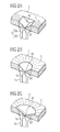
- prismatic deflecting elements 3a, 3b and 3c each with a Part of the light guide 2.
- a light source 5 consisting from a light emitting diode 5a and a light source reflector 5b, shown.
- the light generated in the light emitting diode 5a is either directly or via the light source reflector 5b via a light coupling surface 3d in the prismatic Lichtumlenkiata 3a, 3b, 3c coupled.
- the triangular prismatic light deflecting element 3a directs the light mainly in two opposite directions, as through the dashed illustrated exemplary light rays S shown.
- the conically tapered prismatic Lichtumlenkelement 3b allows a greater proportion of the injected Light also in the light deflecting 3b opposite sides of the light guide 2.
- the conical subdivided tapered prismatic Lichtumlenkelement 3c is a constructive and photometric combination the light deflecting elements 3a, 3b.
- the light deflecting element 3a is preferably for laterally longer light-guiding elements 2 used, the Lichtumlenkelement 3b at one in its geometric Surface area with similar aspect ratios
- Light guide elements and the Lichtumlenkelement 3c for light-guiding elements that make up a geometric combination represent the elements 3a, 3b.
- This in the light guide 2 existing light is directly light exit surface 2a (Fig. 1) radiated or reflected by the reflectors 4, until it is the light guide 2 at the light exit surface 2a leaves and then the area to be screened permeates and illuminates with it.
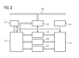
- Fig. 3 shows an example of the construction and the Functioning of a supply and control unit with Temperature control for the display.
- a processing module is shown 11, which via a transformer 13 and a Network 19 receives signals for controlling a display 18. To control the display in a defined way, the processing module uses 11 this data, z. B. temperature curves from a Memory 12 and a temperature driver 15. By means of display driver 16 and backlight driver 17 becomes the display 18 with relevant temperature changes in brightness and contrast readjusted.
Landscapes
- Physics & Mathematics (AREA)
- General Physics & Mathematics (AREA)
- Engineering & Computer Science (AREA)
- Theoretical Computer Science (AREA)
- Optics & Photonics (AREA)
- Planar Illumination Modules (AREA)
- Illuminated Signs And Luminous Advertising (AREA)
Abstract
Description
Die Erfindung betrifft eine Anzeige mit Hinterleuchtungseinheit. Aus dem Stand der Technik sind derartige Anzeigen bekannt, wobei die Anzeige ein zu durchleuchtendes Element mit einer zu durchleuchtenden Fläche und eine Lichtquelle aufweist. Aus dem Stand der Technik sind derartige zu durchleuchtende Flächen beispielsweise als Flüssigkristallanzeigen bekannt, die von einer Vielzahl von Licht gebenden Elementen, beispielsweise eine Leuchtdiodenmatrix hinterleuchtet werden. Diese Lichtquellen weisen eine dazugehörige Versorgungs- und Ansteuereinheit sowie ein oder mehrere Projektionsflächen oder eine Flüssigkristallanzeige auf. Der technisch aufwändigste Teil einer solchen Anzeigeeinheit ist die Lichtquelleneinheit mit der dazugehörigen Versorgungs- und Ansteuereinheit. Derzeit bestehen diese Elemente größtenteils aus einem Baugruppenträger, einer Vielzahl von Leuchtdioden einer Größenordnung von z. B. 20 - 40 Stück und aus einer aus mehreren elektronischen Bauteilen bestehenden Ansteuereinheit, sowie aus einer Versorgungseinheit. Der Nachteil einer solchen elektronischen Anzeige ist der hohe schaltungstechnische Aufwand und die große Anzahl an diskreten Bauteilen, die einen hohen finanziellen Aufwand und eine geringe Gestaltungsfreiheit bedingen. Auch ergeben sich Nachteile bei Fertigung einer solchen Anzeige. Um den Baugruppenträger mit an diesen Komponenten auf einem Bauteilträger zu bestücken, sind in der Regel komplexe Bestimmungsmaschinen und dazugehörige aufwändige Prüfmaschinen erforderlich. Weiterhin unterliegen Lichtquellen wie Leuchtdioden einer Streuung an Farbe und Helligkeit, so dass kostenintensive Lichtquellen Auswahlprozesse durchgeführt werden müssen, um eine homogen ausgeleuchtete Anzeige zu realisieren. Schließlich ist die Ausfall- und Fehlerrate bei einer aus vielen Bauteilen bestehenden Anlage sehr hoch. The invention relates to a display with backlight unit. Such displays are known from the prior art, wherein the display is an element to be screened with a surface to be screened and a light source. From the prior art, such are to be screened For example, surfaces as liquid crystal displays known by a variety of light-giving elements, For example, a light-emitting diode matrix are backlit. These light sources have an associated supply and Control unit and one or more projection or a liquid crystal display. The most technically complex Part of such a display unit is the light source unit with the associated supply and control unit. At present, these elements mostly consist of one Subrack, a variety of LEDs one Magnitude of z. B. 20 - 40 pieces and one of several electronic components existing drive unit, as well as from a supply unit. The disadvantage of such electronic display is the high circuit technology Hassle and the large number of discrete components that make up a high financial expenditure and a low design freedom require. Also, there are disadvantages in manufacturing such a display. To the rack with these Components to be mounted on a component carrier are in the Usually complex determination machines and associated elaborate ones Testing machines required. Furthermore, subject to light sources like light-emitting diodes of a dispersion of color and brightness, so that costly light sources selection processes must be performed to a homogeneously illuminated To realize display. Finally, the failure and error rate in a system consisting of many components very high.
Der Erfindung liegt daher die Aufgabe zugrunde, eine Anzeige mit Hinterleuchtungseinheit anzugeben, die einen vergleichbar einfachen und kostengünstigen Aufbau besitzt. Diese Aufgabe wird dadurch gelöst, dass die Anzeige ein Lichtleitelement mit einem prismatischen Lichtumlenkelement aufweist, dass das Lichtleitelement eine nutzbaren Lichtaustrittsfläche aufweist, die mindestens der zu durchleuchtenden Fläche entspricht und die nutzbare Lichtaustrittsfläche hinter der zu durchleuchtenden Fläche angeordnet ist, dass das Licht der Lichtquelle in das prismatische Lichtumlenkelement einkoppelbar ist, dass mittels des mindestens einen Reflektors Licht, das das Lichtelement außerhalb der nutzbaren Lichtaustrittsfläche verlassen würde, in das Lichtleitelement reflektierbar ist. Hierdurch wird es möglich, mit einem oder einer geringe Anzahl von Lichtquellen eine Hinterleuchtungseinheit aufzubauen. So können als Lichtquellen eine oder eine geringe Anzahl von Leuchtdioden Verwendung finden. Durch diese Lichtquellen und die diesen zugeordneten Lichtumlenk- und Lichtleitelementen ist eine große Material- und Raumeinsparung realisierbar. Weiterhin erfordern eine oder wenige Lichtquellen einen sehr geringen Schaltungs- und Fertigungsaufwand. Die Positionierung der Lichtquellen kann je nach Platzbedarf der Anzeige seitlich oder parallel zur Lichtaustrittsfläche des Lichtleitelementes erfolgen. Hierzu werden nur die Lichtumlenkelemente entsprechend versetzt angeordnet. Das Lichtleitelement ist vorzugsweise etwas größer als die zu durchleuchtende Fläche, beispielsweise eine Flüssigkristallanzeigefläche oder eine sonstige zu durchleuchtende Fläche und ist an den Umrandungen sowie auf dem zu durchleuchtenden Element abgewandten Seite mit Reflektoren versehen, die im einfachsten Fall aus polierten Flächen des Lichtleitelementes bestehen. Vorteilhafterweise bestehen solche Reflektoren aus reflektiv eingefärbtem thermoplastischem Material wie z. B. PBT, PC, PA oder einem duroplastischem Material. Es sind aber auch reflektive Metalle oder Metalllegierungen oder metallbeschichtete Kunststoffe als Reflektoren verwendbar, die dann noch eine zusätzliche Kühlfunktion übernehmen können. Es ist auch möglich, das Lichtleitelement mit Ausnahme der nutzbaren Lichtaustrittsfläche und der Lichtstelle, an dem Licht der Lichtquelle in das prismatische Lichtumlenkelement einkoppelbar ist, mit einem reflektivem Metall zu beschichten, so dass es auch hier zu keinem Lichtverlust kommt. Das Lichtleitelement kann aus einem transparenten oder teiltransparenten Glas oder einem transparenten oder teiltransparenten duroplastischen oder thermoplastischen Kunststoff bestehen. Dadurch, dass das Material des Lichtleitelementes eingefärbt ist, wird die Anzeige insgesamt farbig ausgestaltet. Dadurch, dass der Reflektor aus einer reflektiven Beschichtung des Licht leitenden Elements besteht, wobei die Lichteinkoppelfläche und die nutzbare Lichtaustrittsfläche ausgespart bleiben, ist ein einfacher und effektiver Reflektor realisierbar. Dadurch, dass der Reflektor aus einem oder mehreren diskreten Bauteilen besteht, kann er zusätzlich als Träger des Lichtleitelementes oder sonstiger Bauteile der Anzeige ausgestaltet sein. Zwischen dem Lichtleitelement und dem zu durchscheinenden Element kann zusätzlich ein Diffusor angeordnet sein, um eine noch gleichmäßigere Verteilung des Lichtes zu realisieren. Der Reflektor kann einfacherweise mit einem Baugruppenträger über Schraubverbindungen oder Einrastverbindungen realisiert sein. Eine Einrastverbindung ist einfach herstellbar und auch sicher vor einem Lösen durch Vibrationen, wie diese im Kraftfahrzeug auftreten können. Der Reflektor kann aus einem lichtreflektiven und thermoplastischen oder duroplastischen Material hergestellt sein. Eine besonders gute Reflektion ergibt sich, wenn ein metallbeschichtetes Kunststoffmaterial verwendet wird. Sofern der Reflektor aus einem Metall an einer Metalllegierung oder einem Metallverbundstoff besteht, kann er mit der oder den Lichtquellen direkt oder indirekt thermisch verbunden sein und so die Lichtquelle kühlen. Dadurch, dass sich das Lichtleitelement zu der der Lichtkoppelfläche abgewandten Seite hin verjüngt, wird eine optimale Lichtauskopplung über die Lichtaustrittsfläche erreicht. Das Lichtumlenkelement besteht vorzugsweise entweder aus einer dreieckförmigen prismatischen Aussparung, einer sich konisch verjüngenden prismatischen Aussparung oder aus einer sich konisch verjüngenden unterteilten prismatischen Aussparung. Sofern als Lichtquelle eine Leuchtdiode verwendet wird, ist diese Lichtquelle besonders dauerhaft. Die Lichteinkopplungsfläche kann vorzugsweise entweder senkrecht oder parallel zur Lichtaustrittsfläche angeordnet sein, je nachdem, ob die Lichtquelle seitlich oder unterhalb des auszuleuchtenden Elements angeordnet ist. Dadurch, dass die Lichtaustrittsfläche mit einer Vielzahl von kleinen prismenartigen Zapfen, einer Schicht mit prismenartigen Strukturen oder mit einer Aufrauhung versehen ist, wird die Lichtverteilung weiter optimiert. Dadurch, dass in die Lichteinkoppelfläche Lichtelemente eingesetzt sind, ist eine Anpassung an unterschiedliche Lichtquellen am Strahlcharakteristiken besonders gut zu realisieren. Ein vorhandener Diffusor kann mit einem lichtfilternden oder phosphorisierendem Druck oder Beschichtung versehen sein. Dadurch, dass ein Diffusor direkt mit dem Lichtleitelement durch eine Verbindungsschicht oder einer direkten Materialverbindung in Form von beispielsweise Bedrucken, Aufkleben oder Hinterspritzen kontaktiert ist, wird ein besonders kompakter Aufbau erreicht. Dadurch, dass das Lichtleitelement mit einem Display an der Lichtaustrittsfläche bedruckt ist, wird ein besonders kompakter Aufbau der Anzeige erreicht. Dadurch, dass die Anzeige einen Baugruppenträger aufweist, der eine Leiterplatte mit Eisen- oder Eisenlegierungskern enthält, wird ein guter Wärmeabtransport ermöglicht. Dadurch, dass die Anzeige mit einem Temperatursensor versehen ist, der in einem Steuer- oder Regelkreis die Wärmeleistung der Lichtquelle verändert, wird ein Überhitzen der Anzeige verhindert.The invention is therefore based on the object, a display with backlight unit, which is comparable owns simple and inexpensive construction. This task is achieved by the fact that the display is a light guide comprising a prismatic light deflecting element, that the Light guide has a usable light exit surface, which corresponds at least to the area to be illuminated and the usable light exit surface behind the is arranged through a luminous surface that the light of the Light source in the prismatic Lichtumlenkelement einkoppelbar is that by means of the at least one reflector light, the light element outside the usable light exit surface leave, reflected in the light guide is. This makes it possible, with one or a small Number of light sources to build a backlight unit. Thus, as light sources one or a small number of LEDs find use. Through these light sources and the associated Lichtumlenk- and light-guiding elements is a great material and space savings feasible. Furthermore, one or a few light sources require a very low circuit and manufacturing costs. The Positioning of the light sources may vary depending on the space requirement Display laterally or parallel to the light exit surface of the Lichtleitelementes done. For this purpose, only the Lichtumlenkelemente arranged offset accordingly. The light guide is preferably slightly larger than the one to be screened Surface, for example a liquid crystal display surface or any other area to be screened and is on the edges as well as on the side to be screened element Side with reflectors provided in the simplest Case consist of polished surfaces of the light guide. Advantageously, such reflectors are reflective dyed thermoplastic material such. PBT, PC, PA or a thermosetting material. But they are also reflective Metals or metal alloys or metal-coated Plastics can be used as reflectors, which then still can take on an additional cooling function. It is also possible, the light guide except for the usable Light exit surface and the light spot, at the light of Light source in the prismatic Lichtumlenkelement einkoppelbar is to coat with a reflective metal, so that there is no loss of light here too. The light guide Can be made of transparent or semi-transparent glass or a transparent or semi-transparent thermoset or thermoplastic material. Thereby, that the material of the light guide is colored, is the display overall colored. Because of that Reflector of a reflective coating of the light conducting Elements consists, whereby the Lichteinkoppelfläche and the usable light exit surface is left out is a simple and effective reflector feasible. Thereby, that the reflector consists of one or more discrete components exists, he can additionally as a carrier of the light guide or other components of the display. Between the light guide and the translucent element In addition, a diffuser can be arranged to a to realize even more even distribution of the light. The reflector can easily with a rack implemented via screw or snap-in connections be. A snap connection is easy to produce and also safe from loosening due to vibrations, such as those in the motor vehicle may occur. The reflector can be made from a light-reflective and thermoplastic or thermosetting Be made of material. A particularly good reflection results itself when a metal-coated plastic material is used. If the reflector of a metal on one Metal alloy or a metal composite, he can use the light source (s) directly or indirectly be thermally connected and so cool the light source. Thereby, that the light guide to the light coupling surface tapered away from the side, becomes an optimal Light extraction achieved via the light exit surface. The Lichtumlenkelement preferably consists of either one triangular prismatic recess, one conical tapered prismatic recess or made of a conical shape tapered subdivided prismatic recess. Provided as a light source, a light emitting diode is used This light source is particularly durable. The light coupling surface may preferably be either perpendicular or parallel to Light emission surface can be arranged, depending on whether the Light source at the side or below the element to be illuminated is arranged. Because of the light exit surface with a multitude of small prismatic cones, one Layer with prismatic structures or with a roughening is provided, the light distribution is further optimized. Characterized in that light elements used in the light coupling surface are an adaptation to different light sources to realize the beam characteristics particularly well. An existing diffuser can be equipped with a light-filtering or phosphorescent pressure or coating be. By having a diffuser directly with the light guide through a bonding layer or a direct material connection in the form of, for example, printing, sticking or injection is contacted, becomes a special compact construction achieved. Characterized in that the light guide is printed with a display on the light exit surface, a particularly compact construction of the display is achieved. Thereby, that the display has a rack, the contains a printed circuit board with iron or iron alloy core, a good heat transfer is possible. Thereby, that the display is provided with a temperature sensor, the in a control or regulating circuit, the heat output of the light source changed, overheating of the display is prevented.
Nachfolgend wird die Erfindung anhand der Figuren näher erläutert. Es zeigen:
- Fig. 1:
- den Aufbau einer besonders bevorzugten Anzeige,
- Fig. 2:
- drei vorteilhafte Ausgestaltungen von prismatischen Lichtumlenkelementen im Zusammenwirken mit einer Lichtquelle,
- Fig. 3:
- ein Anwendungsbeispiel für den Aufbau und die Funktionsweise einer Versorgungs- und Ansteuereinheit.
- Fig. 1:
- the construction of a particularly preferred display,
- Fig. 2:
- three advantageous embodiments of prismatic Lichtumlenkelementen in cooperation with a light source,
- 3:
- an application example for the structure and operation of a supply and control unit.
Das erfindungsgemäße Ausführungsbeispiel einer Anzeige in
Fig. 1 auszuleuchtendes Element 1, ein Lichtleitelement 2 mit
einem Lichtumlenkelement 3a, einem Reflektor 4 bestehend aus
einem Reflektorkasten 4a und einem Halbschalenreflektor 4b,
eine Lichtquelle 5 und einen Baugruppenträger 6 auf. Der Reflektorkasten
4a ist als Träger ausgestaltet und weist zusätzlich
ein Verbindungselement 7 auf. In den Reflektorkasten
4a ist das Lichtleitelement 2 und der Halbschalenreflektor 4b
einsetzbar. Weiterhin ist das auszuleuchtende Element 1 in
den Reflektorkasten 4a einrastbar. In Fig. 3 erkennt man
prismatische Umlenkelemente 3a, 3b und 3c jeweils mit einem
Teil des Lichtleitelementes 2. Unterhalb der prismatischen
Lichtumlenkelemente 3a, 3b, 3c ist eine Lichtquelle 5, bestehend
aus einer Leuchtdiode 5a und einem Lichtquellenreflektor
5b, dargestellt. Das in der Leuchtdiode 5a erzeugte Licht
wird entweder direkt oder über den Lichtquellenreflektor 5b
über eine Lichteinkoppelfläche 3d in die prismatischen Lichtumlenkelemente
3a, 3b, 3c eingekoppelt. Das dreieckförmige
prismatische Lichtumlenkelement 3a lenkt das Licht vornehmlich
in zwei entgegen gesetzten Richtungen, wie durch die
strichliert dargestellten beispielhaften Lichtstrahlen S dargestellt.
Das konisch sich verjüngende prismatische Lichtumlenkelement
3b ermöglicht es, einen größeren Anteil des einzukoppelnden
Lichtes auch in die dem Lichtumlenkelement 3b
entgegen gesetzten Seiten des Lichtleitelementes 2. Das konisch
unterteilte sich verjüngende prismatische Lichtumlenkelement
3c ist eine konstruktive und lichttechnische Kombination
der Lichtumlenkelemente 3a, 3b. Das Lichtumlenkelement
3a wird vorzugsweise für seitlich längere Lichtleitelemente 2
eingesetzt, das Lichtumlenkelement 3b bei einem in seiner geometrischen
Flächenausdehnung mit ähnlichen Seitenlängenverhältnissen
Lichtleitelementen und das Lichtumlenkelement 3c
für Lichtleitelemente, die eine geometrische Kombination aus
den Elementen 3a, 3b darstellen. Das im Lichtleitelement 2
vorhandene Licht wird direkt Lichtaustrittsfläche 2a (Fig. 1)
abgestrahlt oder so lange durch die Reflektoren 4 reflektiert,
bis es das Lichtleitelement 2 an der Lichtaustrittsfläche
2a verlässt und dann die zu durchleuchtende Fläche
durchdringt und damit beleuchtet.The inventive embodiment of a display in
Fig. 1 to be illuminated
Fig. 3 zeigt in einem Anwendungsbeispiel den Aufbau und die
Funktionsweise einer Versorgungs- und Ansteuereinheit mit
Temperaturreglung für die Anzeige. Dargestellt wird ein Verarbeitungsmodul
11, welches über einen Übertrager 13 und ein
Netzwerk 19 Signale zur Steuerung einer Anzeige 18 empfängt.
Um die Anzeige definiert anzusteuern, nutzt das Verarbeitungsmodul
11 hierzu Daten, z. B. Temperaturkurven aus einem
Speicher 12 und eines Temperaturtreibers 15. Mittels Displaytreibers
16 und Hinterleuchtungstreiber 17 wird die Anzeige
18 bei relevanten Temperaturänderungen in Helligkeit und Kontrast
nachgeregelt.Fig. 3 shows an example of the construction and the
Functioning of a supply and control unit with
Temperature control for the display. A processing module is shown
11, which via a
Claims (23)
Applications Claiming Priority (2)
| Application Number | Priority Date | Filing Date | Title |
|---|---|---|---|
| DE2003145884 DE10345884A1 (en) | 2003-09-30 | 2003-09-30 | Display with backlight unit |
| DE10345884 | 2003-09-30 |
Publications (3)
| Publication Number | Publication Date |
|---|---|
| EP1521229A2 true EP1521229A2 (en) | 2005-04-06 |
| EP1521229A3 EP1521229A3 (en) | 2006-05-10 |
| EP1521229B1 EP1521229B1 (en) | 2011-03-23 |
Family
ID=34306229
Family Applications (1)
| Application Number | Title | Priority Date | Filing Date |
|---|---|---|---|
| EP04103995A Active EP1521229B1 (en) | 2003-09-30 | 2004-08-20 | Display with back-lighting system |
Country Status (2)
| Country | Link |
|---|---|
| EP (1) | EP1521229B1 (en) |
| DE (2) | DE10345884A1 (en) |
Cited By (1)
| Publication number | Priority date | Publication date | Assignee | Title |
|---|---|---|---|---|
| EP1808716A1 (en) * | 2006-01-16 | 2007-07-18 | Samsung Electro-Mechanics Co., Ltd. | Light guide panel and display device employing the same |
Families Citing this family (2)
| Publication number | Priority date | Publication date | Assignee | Title |
|---|---|---|---|---|
| DE202012101308U1 (en) * | 2012-04-12 | 2013-07-15 | Zumtobel Lighting Gmbh | Luminaire, in particular indicator light |
| DE102017201125B4 (en) | 2017-01-25 | 2019-12-05 | Festo Ag & Co. Kg | Display device and electronic device equipped therewith |
Citations (4)
| Publication number | Priority date | Publication date | Assignee | Title |
|---|---|---|---|---|
| EP0962694A1 (en) * | 1998-06-05 | 1999-12-08 | Citizen Electronics Co., Ltd. | Planar light source unit |
| US6215409B1 (en) * | 1996-05-17 | 2001-04-10 | Solaglo Pty Ltd. | Display apparatus |
| JP2001307528A (en) * | 2000-04-21 | 2001-11-02 | Matsushita Electric Ind Co Ltd | Surface emitting apparatus |
| US6473554B1 (en) * | 1996-12-12 | 2002-10-29 | Teledyne Lighting And Display Products, Inc. | Lighting apparatus having low profile |
Family Cites Families (1)
| Publication number | Priority date | Publication date | Assignee | Title |
|---|---|---|---|---|
| US6930737B2 (en) * | 2001-01-16 | 2005-08-16 | Visteon Global Technologies, Inc. | LED backlighting system |
-
2003
- 2003-09-30 DE DE2003145884 patent/DE10345884A1/en not_active Ceased
-
2004
- 2004-08-20 DE DE200450012327 patent/DE502004012327D1/en active Active
- 2004-08-20 EP EP04103995A patent/EP1521229B1/en active Active
Patent Citations (4)
| Publication number | Priority date | Publication date | Assignee | Title |
|---|---|---|---|---|
| US6215409B1 (en) * | 1996-05-17 | 2001-04-10 | Solaglo Pty Ltd. | Display apparatus |
| US6473554B1 (en) * | 1996-12-12 | 2002-10-29 | Teledyne Lighting And Display Products, Inc. | Lighting apparatus having low profile |
| EP0962694A1 (en) * | 1998-06-05 | 1999-12-08 | Citizen Electronics Co., Ltd. | Planar light source unit |
| JP2001307528A (en) * | 2000-04-21 | 2001-11-02 | Matsushita Electric Ind Co Ltd | Surface emitting apparatus |
Non-Patent Citations (1)
| Title |
|---|
| PATENT ABSTRACTS OF JAPAN Bd. 2002, Nr. 03, 3. April 2002 (2002-04-03) & JP 2001 307528 A (MATSUSHITA ELECTRIC IND CO LTD), 2. November 2001 (2001-11-02) * |
Cited By (3)
| Publication number | Priority date | Publication date | Assignee | Title |
|---|---|---|---|---|
| EP1808716A1 (en) * | 2006-01-16 | 2007-07-18 | Samsung Electro-Mechanics Co., Ltd. | Light guide panel and display device employing the same |
| US7573543B2 (en) | 2006-01-16 | 2009-08-11 | Samsung Electro-Mechanics Co., Ltd | Light guide panel and display device employing the same |
| EP2293124A1 (en) * | 2006-01-16 | 2011-03-09 | Samsung LED Co., Ltd. | Light guide panel and display device employing the same |
Also Published As
| Publication number | Publication date |
|---|---|
| EP1521229A3 (en) | 2006-05-10 |
| DE10345884A1 (en) | 2005-05-12 |
| EP1521229B1 (en) | 2011-03-23 |
| DE502004012327D1 (en) | 2011-05-05 |
Similar Documents
| Publication | Publication Date | Title |
|---|---|---|
| EP1166013B1 (en) | Front-illuminated Display Device | |
| EP3790756B1 (en) | Operating and/or display element for a motor vehicle | |
| WO2003034125A1 (en) | Display device | |
| DE202005021754U1 (en) | Light-emitting panel | |
| DE202012013353U1 (en) | Low profile optical lighting assembly for use in a vehicle exterior mirror | |
| DE102004015903A1 (en) | Light emitting diode used in e.g. notebook type personal computer, has metallic reflective layer formed at upper surface of transparent resin which seals LED chip | |
| DE102005056654A1 (en) | A light-emitting device comprising a plurality of overlapping panels forming recesses from which light is emitted | |
| DE102005024083A1 (en) | Flat, light-emitting device | |
| EP1696404A1 (en) | Light emitting diode assembly | |
| DE112012006210T5 (en) | Backlight module | |
| WO2000039501A1 (en) | Light source element with lateral, angular light injection | |
| DE102006001490A1 (en) | lighting device | |
| DE112019001649B4 (en) | ELECTRICAL DEVICE FOR A VEHICLE FOOTBOARD | |
| EP1521229B1 (en) | Display with back-lighting system | |
| EP1505560B1 (en) | Light guide member for multisegment displays | |
| EP3553371A1 (en) | Lamp for motor vehicle lights comprising a plate like light guide and motor vehicle light equipped with the same | |
| EP3853518B1 (en) | Light module, in particular for use in a lighting device for a motor vehicle | |
| DE19860696A1 (en) | Lighting element, especially for back lighting of liquid crystal display (LCD) or for ambient lighting, has light guide supplied with light at oblique angle | |
| DE102021006448A1 (en) | Backlight unit and display device having the same | |
| DE202020100814U1 (en) | Luminaire for use in an outside mirror of a motor vehicle and vehicle outside mirror with the same | |
| DE10143357B4 (en) | Rigid light guide | |
| DE10108073B4 (en) | lighting device | |
| DE10303308A1 (en) | instrument cluster | |
| WO2004051318A2 (en) | Illumination arrangement | |
| DE10355610B4 (en) | Arrangement for backlighting a viewing element |
Legal Events
| Date | Code | Title | Description |
|---|---|---|---|
| PUAI | Public reference made under article 153(3) epc to a published international application that has entered the european phase |
Free format text: ORIGINAL CODE: 0009012 |
|
| AK | Designated contracting states |
Kind code of ref document: A2 Designated state(s): AT BE BG CH CY CZ DE DK EE ES FI FR GB GR HU IE IT LI LU MC NL PL PT RO SE SI SK TR |
|
| AX | Request for extension of the european patent |
Extension state: AL HR LT LV MK |
|
| PUAL | Search report despatched |
Free format text: ORIGINAL CODE: 0009013 |
|
| AK | Designated contracting states |
Kind code of ref document: A3 Designated state(s): AT BE BG CH CY CZ DE DK EE ES FI FR GB GR HU IE IT LI LU MC NL PL PT RO SE SI SK TR |
|
| AX | Request for extension of the european patent |
Extension state: AL HR LT LV MK |
|
| 17P | Request for examination filed |
Effective date: 20061110 |
|
| AKX | Designation fees paid |
Designated state(s): DE FR IT |
|
| 17Q | First examination report despatched |
Effective date: 20070115 |
|
| RAP1 | Party data changed (applicant data changed or rights of an application transferred) |
Owner name: CONTINENTAL AUTOMOTIVE GMBH |
|
| GRAP | Despatch of communication of intention to grant a patent |
Free format text: ORIGINAL CODE: EPIDOSNIGR1 |
|
| GRAS | Grant fee paid |
Free format text: ORIGINAL CODE: EPIDOSNIGR3 |
|
| GRAA | (expected) grant |
Free format text: ORIGINAL CODE: 0009210 |
|
| AK | Designated contracting states |
Kind code of ref document: B1 Designated state(s): DE FR IT |
|
| REF | Corresponds to: |
Ref document number: 502004012327 Country of ref document: DE Date of ref document: 20110505 Kind code of ref document: P |
|
| REG | Reference to a national code |
Ref country code: DE Ref legal event code: R096 Ref document number: 502004012327 Country of ref document: DE Effective date: 20110505 |
|
| PLBE | No opposition filed within time limit |
Free format text: ORIGINAL CODE: 0009261 |
|
| STAA | Information on the status of an ep patent application or granted ep patent |
Free format text: STATUS: NO OPPOSITION FILED WITHIN TIME LIMIT |
|
| 26N | No opposition filed |
Effective date: 20111227 |
|
| REG | Reference to a national code |
Ref country code: DE Ref legal event code: R097 Ref document number: 502004012327 Country of ref document: DE Effective date: 20111227 |
|
| PGFP | Annual fee paid to national office [announced via postgrant information from national office to epo] |
Ref country code: IT Payment date: 20120822 Year of fee payment: 9 |
|
| PG25 | Lapsed in a contracting state [announced via postgrant information from national office to epo] |
Ref country code: IT Free format text: LAPSE BECAUSE OF NON-PAYMENT OF DUE FEES Effective date: 20130820 |
|
| REG | Reference to a national code |
Ref country code: FR Ref legal event code: PLFP Year of fee payment: 13 |
|
| REG | Reference to a national code |
Ref country code: FR Ref legal event code: PLFP Year of fee payment: 14 |
|
| REG | Reference to a national code |
Ref country code: DE Ref legal event code: R084 Ref document number: 502004012327 Country of ref document: DE |
|
| REG | Reference to a national code |
Ref country code: FR Ref legal event code: PLFP Year of fee payment: 15 |
|
| REG | Reference to a national code |
Ref country code: DE Ref legal event code: R081 Ref document number: 502004012327 Country of ref document: DE Owner name: CONTINENTAL AUTOMOTIVE TECHNOLOGIES GMBH, DE Free format text: FORMER OWNER: CONTINENTAL AUTOMOTIVE GMBH, 30165 HANNOVER, DE |
|
| PGFP | Annual fee paid to national office [announced via postgrant information from national office to epo] |
Ref country code: DE Payment date: 20220531 Year of fee payment: 19 |
|
| PGFP | Annual fee paid to national office [announced via postgrant information from national office to epo] |
Ref country code: FR Payment date: 20220823 Year of fee payment: 19 |
|
| P01 | Opt-out of the competence of the unified patent court (upc) registered |
Effective date: 20230522 |
|
| REG | Reference to a national code |
Ref country code: DE Ref legal event code: R119 Ref document number: 502004012327 Country of ref document: DE |