EP1521031A2 - Light emitting diode lighting appliance and light emitting diode emergency light using the same - Google Patents
Light emitting diode lighting appliance and light emitting diode emergency light using the same Download PDFInfo
- Publication number
- EP1521031A2 EP1521031A2 EP04256072A EP04256072A EP1521031A2 EP 1521031 A2 EP1521031 A2 EP 1521031A2 EP 04256072 A EP04256072 A EP 04256072A EP 04256072 A EP04256072 A EP 04256072A EP 1521031 A2 EP1521031 A2 EP 1521031A2
- Authority
- EP
- European Patent Office
- Prior art keywords
- emitting diode
- light emitting
- barrel
- lens
- light
- Prior art date
- Legal status (The legal status is an assumption and is not a legal conclusion. Google has not performed a legal analysis and makes no representation as to the accuracy of the status listed.)
- Withdrawn
Links
Images

Classifications
-
- F—MECHANICAL ENGINEERING; LIGHTING; HEATING; WEAPONS; BLASTING
- F21—LIGHTING
- F21S—NON-PORTABLE LIGHTING DEVICES; SYSTEMS THEREOF; VEHICLE LIGHTING DEVICES SPECIALLY ADAPTED FOR VEHICLE EXTERIORS
- F21S8/00—Lighting devices intended for fixed installation
- F21S8/02—Lighting devices intended for fixed installation of recess-mounted type, e.g. downlighters
-
- F—MECHANICAL ENGINEERING; LIGHTING; HEATING; WEAPONS; BLASTING
- F21—LIGHTING
- F21S—NON-PORTABLE LIGHTING DEVICES; SYSTEMS THEREOF; VEHICLE LIGHTING DEVICES SPECIALLY ADAPTED FOR VEHICLE EXTERIORS
- F21S9/00—Lighting devices with a built-in power supply; Systems employing lighting devices with a built-in power supply
- F21S9/02—Lighting devices with a built-in power supply; Systems employing lighting devices with a built-in power supply the power supply being a battery or accumulator
- F21S9/022—Emergency lighting devices
-
- F—MECHANICAL ENGINEERING; LIGHTING; HEATING; WEAPONS; BLASTING
- F21—LIGHTING
- F21V—FUNCTIONAL FEATURES OR DETAILS OF LIGHTING DEVICES OR SYSTEMS THEREOF; STRUCTURAL COMBINATIONS OF LIGHTING DEVICES WITH OTHER ARTICLES, NOT OTHERWISE PROVIDED FOR
- F21V5/00—Refractors for light sources
- F21V5/04—Refractors for light sources of lens shape
-
- F—MECHANICAL ENGINEERING; LIGHTING; HEATING; WEAPONS; BLASTING
- F21—LIGHTING
- F21V—FUNCTIONAL FEATURES OR DETAILS OF LIGHTING DEVICES OR SYSTEMS THEREOF; STRUCTURAL COMBINATIONS OF LIGHTING DEVICES WITH OTHER ARTICLES, NOT OTHERWISE PROVIDED FOR
- F21V7/00—Reflectors for light sources
- F21V7/0091—Reflectors for light sources using total internal reflection
-
- F—MECHANICAL ENGINEERING; LIGHTING; HEATING; WEAPONS; BLASTING
- F21—LIGHTING
- F21V—FUNCTIONAL FEATURES OR DETAILS OF LIGHTING DEVICES OR SYSTEMS THEREOF; STRUCTURAL COMBINATIONS OF LIGHTING DEVICES WITH OTHER ARTICLES, NOT OTHERWISE PROVIDED FOR
- F21V21/00—Supporting, suspending, or attaching arrangements for lighting devices; Hand grips
- F21V21/02—Wall, ceiling, or floor bases; Fixing pendants or arms to the bases
- F21V21/04—Recessed bases
-
- F—MECHANICAL ENGINEERING; LIGHTING; HEATING; WEAPONS; BLASTING
- F21—LIGHTING
- F21Y—INDEXING SCHEME ASSOCIATED WITH SUBCLASSES F21K, F21L, F21S and F21V, RELATING TO THE FORM OR THE KIND OF THE LIGHT SOURCES OR OF THE COLOUR OF THE LIGHT EMITTED
- F21Y2115/00—Light-generating elements of semiconductor light sources
- F21Y2115/10—Light-emitting diodes [LED]
Definitions
- This invention relates to a light emitting diode lighting appliance and a light emitting diode emergency light using thereof.
- a light emitting diode (hereinafter, referred to as LED) light source and an LED lighting appliance it was made to make the light emitted from LED glare in the predetermined direction with a lens are known.
- LED light emitting diode
- PCT/JP2002-543594 A discloses an LED light source with lens attached on a transparent resin body covering an LED, for condensing lights emitted from the LED to enhance the light of beam.
- the LED light source with lens has only a feature of condensing lights emitted from the LED. Therefore, in the LED light source with lens it is difficult to take a batwing luminous intensity pattern.
- JP1I-162232A discloses an LED lighting appliance comprising an LED array module with a plurality of LEDs and a lens plate opposing to the LED array module, wherein an illumination angle of light emitted from the LED array module is controlled by the lens plate.
- the LED lighting appliance it is difficult to control the overall illumination intensity pattern of the lights illuminated from the plurality of LEDs. Further, the LED lighting appliance is hard to be miniaturized. Therefore, the LED lighting appliance is not suitable for use of ceiling-mount emergency light.
- a ceiling-mounted type and a ceiling-recessed type lighting appliance are required to equally illuminate a prescribed floor range around a portion directly below the appliance. Therefore, the lighting appliance needs to have a so-called batwing luminous intensity pattern in which a luminous intensity on the light axis of the lighting appliance is low but the luminous intensity rises with increase of distance from the light axis. Especially an emergency light needs to have this batwing luminous intensity pattern.
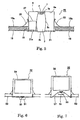
- LED lighting appliances as shown in Figs. 6 and 7.
- a lens 51 formed in a round bun shape which is defined a recession in the center, is arranged in the front of LED 50, and a light applied to the lens 51 from the LED 50 is refracted in a lateral direction, thereby the LED lighting appliance takes a batwing luminous intensity pattern.
- the LED lighting appliances as shown in Fig. 6, the lens 51 projects down from the ceiling in the state that the appliance is mounted in the ceiling, the LED lighting appliance 52 has a problem of bad appearance.
- the LED lighting appliances 55 as shown in Fig. 7, the undersurface of the appliance and the entire of the lens 51 expose at the ceiling, in the state that the appliance is mounted in the ceiling, the LED lighting appliance 55 also has a problem of bad appearance.
- the present invention has an object to provide an LED lighting appliance and an LED emergency light using thereof both having favorable batwing luminous intensity pattern, and good appearance, in the state of mounted on the ceiling.
- an aspect of the LED lighting appliance is provided with; a housing having an open end and a bottom, a LED, a lens, and a lighting device for lighting the LED, respectively accommodated in the housing, characterized in that the LED is placed to the bottom side of the housing, the lens has a barrel-shape body having a concave incidence end directly facing the LED, a generally flat exit end exposing to the open end and a sidewall bulging in a barrel-shape, wherein the concave incidence end is defined that a light, emitted from the LED and entered in the barrel-shape body at the concave surface, performs substantially a total reflection on a major portion of an interface defined by the sidewall, and the reflected light refracts at the exit end and exits from the barrel-shape body in the receding direction from a central axis of the barrel-shape body.
- the LED can be used by only one, or a plurality of LEDs is used in used in collected in a small area.
- a phrase "--- has a circular section in the vertical plane to the central axis" means that a lens is rotationally symmetrical in relation to the central axis of the lens.
- Lenses may be made of transparent grass or resin.
- Lighting devices can be located in any position, e.g., in a housing, on an outside of housing, or a position distant from the housing.
- a part of lights entered into the lens from the LED exits in the receding direction from the central axis of the lens. Therefore, sufficient illumination intensity is obtained at a position remote from the portion directly under the lighting appliance. Since a major part of the lights entered into the lens performs a total reflection on the interface defined by the sidewall of the lens and exits from the lens, high illumination efficiency is obtained.
- the concave incidence end is defined in a cone-shaped hollow so that the light entered in the barrel-shape body around a central portion of the incidence end, and an angular separation of the cone-shaped hollow is defined that the light entered in the barrel-shape body around the center of the incidence end, performs substantially a total reflection on an exit end side portion of the interface.
- a suitable angular separation of the cone-shape hollow is defined in accordance with the distance between the incidence end of the lens and the LED.
- the entire of the light entered into the lens performs a total reflection on the Interface defined by the sidewall of the lens, moreover a high illumination efficiency is obtained.
- More another aspect of the LED lighting appliance according to the present invention is characterized by that the lens is defined that the light, performed substantially a total reflection on the interface, exits from the barrel-shape body in parallel to the central axis of the barrel-shape body, and the exit end is made larger in diameter than the incidence end.
- a part of the light entered into the lens exits from the lens in the direction parallel to the central axis of the lens without bouncing on the interface. Therefore, high illumination intensity is obtained around the portion directly under the LED lighting appliance.
- Still another aspect of the LED lighting appliance according to the present invention is provided with; a housing having an open end and a bottom, an LED, a lens, a lighting device lighting the LED, and a support member for supporting the lens, respectively accommodated in the housing, characterized in that the LED is placed to the bottom of the housing, the lens has a concave incidence end directly facing the LED, an exit end made larger in diameter than the incidence end and a sidewall shaped that a major part of lights, emitted from the LED and entered in its body, performs substantially a total reflection thereon, and the reflected light exits from the barrel-shape body through the exit end in the receding direction from a central axis of the body, and the support member supports the exit end of the lens.
- the LED By covering the sidewall of the lens with a reflecting film such as a metal film for preventing leakage of light from the sidewall of the lens, moreover high illumination efficiency can be obtained. Since the LED is placed on an extension of the central axis of the lens, the light emitted from the LED efficiently enters in to the lens. Since the exit end of the lens is formed smaller than the maximum diameter of at the middle portion of the body, the exit end of the lens can be supported certainly and easily by the support member with the aperture slightly larger than the exit end, without making the lens project from the aperture.
- a reflecting film such as a metal film for preventing leakage of light from the sidewall of the lens
- the light emitted from the LED efficiently illuminates the objective surface to be illuminated, and a favorable batwing luminous intensity pattern can be obtained.
- An aspect of the LED emergency light is provided with; a housing having an open end and a bottom, an LED, a lens, a battery, a lighting device for feeding the LED with a DC current from the battery at an electric power failure, respectively accommodated in the housing, characterized in that the LED is placed to the bottom of the housing, the lens has a barrel-shape body having a concave incidence end directly facing the LED, a generally flat exit end exposing to the open end and a sidewall bulging in a barrel-shape, wherein the concave incidence end is defined that a light, emitted from the LED and entered in the barrel-shape body at around the center of the concave surface, performs substantially a total reflection on a major portion of an interface defined by the sidewall, and the reflected light refracts at the exit end and exits from the barrel-shape body in the receding direction from a central axis of the barrel-shape body.
- a floor portion distant from the portion directly under the lighting appliance is illuminated at sufficient illumination intensity. Furthermore, the LED is turned on by the battery at an electric power failure.
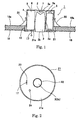
- Fig. 1 shows an LED emergency light according to one embodiment of the present invention, in a schematic section.
- Fig. 2 also shows the LED emergency light according to one embodiment of the present invention, in a schematic front view.
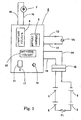
- Fig. 3 shows wiring connections in the LED emergency light according to the one embodiment of the present invention.
- Fig. 4 shows a schematic configuration of the lens in the LED emergency light according to the one embodiment of the present invention and light paths passing through the lens.
- the LED emergency light 1 comprises an LED 2, a lens 3, a lighting unit 8, a plurality of batteries 5, and a housing 6.
- the housing has an open end and a bottom 6a.
- the LED 2 is accommodated in housing 6 on the center of a base 7 which is mounted the bottom 6a of the housing 6.
- the LED 2 is a white light LED.
- the lens 3 has a barrel-shape body, and is made of, e.g., glass.
- One end 3a of the lens 3 is shaped concave with a cone-shaped hollow.
- the lens 3 directly faces the LED 2 at the one end 3a thereof. The shape of the lens 3 will be described in detail later.
- the lighting unit 8 comprises a lighting device 4, a battery charger 9, a switching circuit 10, an inspection switch 11, and a charge monitor 12.
- the lighting device 4 lights the LED 2 by feeding the LED 2 with a prescribed current.
- the batteries 5 feed the lighting device 4 with a DC voltage.
- a pair of AC power lines 13, 13 is led out from the battery charger 9. These AC power lines 13, 13 are connected to the commercial AC power source Vs.
- a pair of DC power lines 14, 14 is led out from the battery charger 9 or the lighting device 4. These DC power lines 14, 14 are connected to the batteries 5 through a connector 15. The batteries 5 are connected in series with each. And a fuse F1 is inserted in the series connection of the batteries 5.
- a pair of lamp lines 16, 16 is led out from the lighting device 4. These lamp lines 16 and 16 are connected to the LED 2.
- the battery charger 9 is constituted to charge the batteries 5.
- the charge monitor 12 is turned on.
- the switching circuit 10 operates at an electric power failure, and connects the batteries 5 to the lighting device 4.
- a drawstring thread 17 of the inspection switch 11 is pulled down, the inspection switch 11 operates, and also connects the batteries 5 to the lighting device 4. Therefore, it is able to be checked whether the LED 2 is operable or not at an electric power failure by operating the inspection switch 11.
- the housing 6 has a cylindrical shape with the open end in the lower surface so as to be mounted to an opening 19 of a ceiling 18.
- Two or more leaf springs 20 are fixed on the sidewall of the housing 6.
- a ring-frame 21 is detachably attached to the ceiling 18 around the opening 19 for supporting the housing 6. After the housing 6 is inserted in the opening 19 of the ceiling 18, tip ends of the leaf springs 20 are imposed against the back 18a of the ceiling 18 by their own elasticity. Therefore, the leaf springs 20 hold the ceiling 18 with the ring-frame 21 by the elasticity. Consequently, the LED emergency light 1 is fixed to the ceiling 18.
- the ring-frame 21 is defined an aperture 22 in their center to which the exit end 3b of the lens 3 exposes.
- the ring-frame 21 is also defined a slit 23 in their center and a pore 24 in the middle of their center and their peripheral. Through the slit 23, the drawstring thread 17 of the inspection switch 11 is led out.
- the charge monitor 12 faces the pore 24.
- the housing 6 accommodates the LED 2, the lens 3, the battery pack 5, and the lighting unit 8.
- the LED 2 is located on an extension of the central axis of the housing 6.
- the lens 3 is arranged in the housing 6 that the central axis of the lens 3 agrees with the central axis of the housing 6. Therefore, the incidence end 3a of the tens 3 directly faces the LED 2.
- the exit end 3b of the lens 3 exposes the outside 21a through the aperture 22 of the ring-frame 21.
- the batteries 5 and the lighting unit 8 are fixed at the positions in the opposite sides of the lens 3 with fasteners (not shown).
- the lens 3 has the concave incidence end 3a with the cone-shape hollow.
- the exit end 3b is formed approximately in the flat surface.
- the sidewall 3c of the lens 3 is thinned at the sides of the incidence end 3a and the exit end 3b. While the sidewall 3c bulges in a barrel-shape at its middle portion.
- the lens 3 has a circular section in the vertical plane to the central axis across the incidence end 3a to the exit end 3b.
- the diameter of the exit end 3b is made larger than that of the incidence end 3a.
- the concave is defined that the cone-shape hollow of the concave incidence end 3a has a predetermined angular separation K1.
- the LED 2 When the LED 2 turns on, the light emitted from the LED 2 enters into the lens 3 through the incidence end 3a. A part of the light entered into the lens 3 performs substantially a total inflection on an interface defined by the sidewall 3c, and the reflected tights refracts at the exit end 3b and exits from the body. Another part of the light entered in the lens 3 is absorbed in the body.
- the angular separation K1 of the cone-shape hollow of the concave incidence end 3a is defined by following conditions a, b and c.
- the lights entered into the body at around the portion between the center of the cone-shaped hollow and the peripheral of the concave incidence end 3a performs substantially a total reflection on a major portion of the interface, and the reflected light refracts at the exit end 3b and then exits from the body in the receding direction from the central axis of the body.
- the lights entered into the body at around the center of the cone-shaped hollow of the concave incidence end 3a performs substantially a total reflection on a portion of the interface near the exit end 3b, and the reflected light refracts at the exit end 3b and then exits from the body in the receding direction from the central axis of the body.
- the lights entered into the body at around the peripheral of the cone-shaped hollow of the concave incidence end 3a performs substantially a total reflection on a portion of the interface near the incidence end 3a, and the reflected light exits from the body without refraction in the direction parallel to the central axis of the body.
- the diameter of the exit end 3b of the lens 3 is made larger than the diameter of the incidence end 3a, the light as shown by the arrow line exits from the lens through the exit end, without g radiation of the light shown by the arrow line C is carried out from the exit end 3b, without bouncing on the interface.
- the LED lighting appliance 1 has a favorable batwing luminous intensity pattern around the central axis of the lens 3.
- the illumination intensity on the portions increase.
- the lights shown by the arrow lines A1, A2, perform total reflections on the interface defined by the sidewall 3c. Since the light, shown by the arrow line B, entered in the lens 3 at around the center of the incidence end, also performs a total reflection on the interface defined by the sidewall 3c, the exit light has relatively high proportion in relation to the incidence light, and therefore high illumination efficiency is obtained.
- the LED emergency light 1 since the LED emergency light 1 has the favorable batwing luminous intensity pattern, the LED emergency light 1 exerts very favorable illumination characteristics at an electric power failure. Since LED 2 operates with low power consumption, the batteries can be miniaturized. Then, the LED emergency light 1 is miniaturized and is saved weight. Since the exit end 3c of the lens 3 exposes the outside 21a at the aperture 22 of the ring-frame 21 without projecting through the aperture. Thus the LED emergency light 1 has a good appearance.
- Fig. 5 shows an LED lighting appliance according to the second embodiment of the present invention, in a schematic section.
- Fig. 5 the same elements as those, as shown in Fig. 1, are assigned with the like reference numerals and not discussed herein.
- the LED lighting appliance 26, shown in Fig. 5, is different from the LED emergency light 1, shown in Fig. 1, by that both of the batteries 5 and the lighting unit 8 are replaced with a lighting device 27.
- This LED lighting appliance 26 is a so-called downlight.
- the lighting device 27 is connected to the commercial AC power source Vs (see Fig. 3).
- the lighting device 27a converts the AC current to the DC current voltage and then feeds the LED 2 the DC current by appropriately adjusting the voltage of the DC current.
- the LED lighting appliance 26 has a favorable batwing luminous intensity pattern, and thus it is able to illuminate any objective surface to be illuminated, such as floor.
- the present invention can provide LED lighting appliances having favorable batwing illumination efficiency and high illumination efficiency.
- the present invention can provide LED emergency light having a favorable batwing illumination intensity pattern and operable by batteries at an electric power failure. Since the LED operates with low power consumption, the batteries can be miniaturized. Then, the LED emergency light is miniaturized and is saved weight.
Landscapes
- Engineering & Computer Science (AREA)
- General Engineering & Computer Science (AREA)
- Non-Portable Lighting Devices Or Systems Thereof (AREA)
Abstract
Description
- This application is based upon and claims the benefit of priority from the prior Japanese Patent Application JP2003-342134 filed on September 30, 2003, the entire content of which is Incorporated herein by reference.
- This invention relates to a light emitting diode lighting appliance and a light emitting diode emergency light using thereof.
- A light emitting diode (hereinafter, referred to as LED) light source and an LED lighting appliance it was made to make the light emitted from LED glare in the predetermined direction with a lens are known. For example, PCT/JP2002-543594 A discloses an LED light source with lens attached on a transparent resin body covering an LED, for condensing lights emitted from the LED to enhance the light of beam.
- In the LED light source with lens, has only a feature of condensing lights emitted from the LED. Therefore, in the LED light source with lens it is difficult to take a batwing luminous intensity pattern.
- JP1I-162232A discloses an LED lighting appliance comprising an LED array module with a plurality of LEDs and a lens plate opposing to the LED array module, wherein an illumination angle of light emitted from the LED array module is controlled by the lens plate.
- However, in the LED lighting appliance, it is difficult to control the overall illumination intensity pattern of the lights illuminated from the plurality of LEDs. Further, the LED lighting appliance is hard to be miniaturized. Therefore, the LED lighting appliance is not suitable for use of ceiling-mount emergency light.
- Generally, a ceiling-mounted type and a ceiling-recessed type lighting appliance are required to equally illuminate a prescribed floor range around a portion directly below the appliance. Therefore, the lighting appliance needs to have a so-called batwing luminous intensity pattern in which a luminous intensity on the light axis of the lighting appliance is low but the luminous intensity rises with increase of distance from the light axis. Especially an emergency light needs to have this batwing luminous intensity pattern.
- There is known a lighting appliance in which the light emitted from a light source reflects on a reflector, and the light has a batwing luminous intensity pattern as a whole. However, it is very difficult to form the reflection surface of the reflector in a curved surface for taking a required illumination intensity pattern.
- Then, there is known LED lighting appliances as shown in Figs. 6 and 7. In the appliances, a
lens 51 formed in a round bun shape which is defined a recession in the center, is arranged in the front ofLED 50, and a light applied to thelens 51 from theLED 50 is refracted in a lateral direction, thereby the LED lighting appliance takes a batwing luminous intensity pattern. Since in the LED lighting appliances, as shown in Fig. 6, thelens 51 projects down from the ceiling in the state that the appliance is mounted in the ceiling, theLED lighting appliance 52 has a problem of bad appearance. Since in theLED lighting appliances 55, as shown in Fig. 7, the undersurface of the appliance and the entire of thelens 51 expose at the ceiling, in the state that the appliance is mounted in the ceiling, theLED lighting appliance 55 also has a problem of bad appearance. - The present invention has an object to provide an LED lighting appliance and an LED emergency light using thereof both having favorable batwing luminous intensity pattern, and good appearance, in the state of mounted on the ceiling.
- In order to achieve the object, an aspect of the LED lighting appliance according to the present invention is provided with; a housing having an open end and a bottom, a LED, a lens, and a lighting device for lighting the LED, respectively accommodated in the housing, characterized in that the LED is placed to the bottom side of the housing, the lens has a barrel-shape body having a concave incidence end directly facing the LED, a generally flat exit end exposing to the open end and a sidewall bulging in a barrel-shape, wherein the concave incidence end is defined that a light, emitted from the LED and entered in the barrel-shape body at the concave surface, performs substantially a total reflection on a major portion of an interface defined by the sidewall, and the reflected light refracts at the exit end and exits from the barrel-shape body in the receding direction from a central axis of the barrel-shape body.
- In the present invention and in the following respective invention, the definition and the meaning of the technical terms are as follows, as far as no special notice is mentioned. The LED can be used by only one, or a plurality of LEDs is used in used in collected in a small area.
- A phrase "--- has a circular section in the vertical plane to the central axis" means that a lens is rotationally symmetrical in relation to the central axis of the lens. Lenses may be made of transparent grass or resin.
- Lighting devices can be located in any position, e.g., in a housing, on an outside of housing, or a position distant from the housing.
- According to the fist aspect of the invention, a part of lights entered into the lens from the LED exits in the receding direction from the central axis of the lens. Therefore, sufficient illumination intensity is obtained at a position remote from the portion directly under the lighting appliance. Since a major part of the lights entered into the lens performs a total reflection on the interface defined by the sidewall of the lens and exits from the lens, high illumination efficiency is obtained.
- Another aspect of the LED lighting appliance according to the present invention is characterized by that the concave incidence end is defined in a cone-shaped hollow so that the light entered in the barrel-shape body around a central portion of the incidence end, and an angular separation of the cone-shaped hollow is defined that the light entered in the barrel-shape body around the center of the incidence end, performs substantially a total reflection on an exit end side portion of the interface.
- A suitable angular separation of the cone-shape hollow is defined in accordance with the distance between the incidence end of the lens and the LED.
- According to the second aspect of the invention, since the entire of the light entered into the lens performs a total reflection on the Interface defined by the sidewall of the lens, moreover a high illumination efficiency is obtained.
- More another aspect of the LED lighting appliance according to the present invention is characterized by that the lens is defined that the light, performed substantially a total reflection on the interface, exits from the barrel-shape body in parallel to the central axis of the barrel-shape body, and the exit end is made larger in diameter than the incidence end.
- According to the third aspect of the invention, a part of the light entered into the lens exits from the lens in the direction parallel to the central axis of the lens without bouncing on the interface. Therefore, high illumination intensity is obtained around the portion directly under the LED lighting appliance.
- Still another aspect of the LED lighting appliance according to the present invention is provided with; a housing having an open end and a bottom, an LED, a lens, a lighting device lighting the LED, and a support member for supporting the lens, respectively accommodated in the housing, characterized in that the LED is placed to the bottom of the housing, the lens has a concave incidence end directly facing the LED, an exit end made larger in diameter than the incidence end and a sidewall shaped that a major part of lights, emitted from the LED and entered in its body, performs substantially a total reflection thereon, and the reflected light exits from the barrel-shape body through the exit end in the receding direction from a central axis of the body, and the support member supports the exit end of the lens.
- By increasing the depth of the concave of the incidence end, much more light from the LED can be entered into the lens.
- By covering the sidewall of the lens with a reflecting film such as a metal film for preventing leakage of light from the sidewall of the lens, moreover high illumination efficiency can be obtained. Since the LED is placed on an extension of the central axis of the lens, the light emitted from the LED efficiently enters in to the lens. Since the exit end of the lens is formed smaller than the maximum diameter of at the middle portion of the body, the exit end of the lens can be supported certainly and easily by the support member with the aperture slightly larger than the exit end, without making the lens project from the aperture.
- According to the fourth aspect of the invention, the light emitted from the LED efficiently illuminates the objective surface to be illuminated, and a favorable batwing luminous intensity pattern can be obtained.
- An aspect of the LED emergency light according to the present invention is provided with; a housing having an open end and a bottom, an LED, a lens, a battery, a lighting device for feeding the LED with a DC current from the battery at an electric power failure, respectively accommodated in the housing, characterized in that the LED is placed to the bottom of the housing, the lens has a barrel-shape body having a concave incidence end directly facing the LED, a generally flat exit end exposing to the open end and a sidewall bulging in a barrel-shape, wherein the concave incidence end is defined that a light, emitted from the LED and entered in the barrel-shape body at around the center of the concave surface, performs substantially a total reflection on a major portion of an interface defined by the sidewall, and the reflected light refracts at the exit end and exits from the barrel-shape body in the receding direction from a central axis of the barrel-shape body.
- According to the fifth aspect of the invention, a floor portion distant from the portion directly under the lighting appliance is illuminated at sufficient illumination intensity. Furthermore, the LED is turned on by the battery at an electric power failure.
- A more complete appreciation of the present invention and many of the attendant advantages thereof will be readily obtained as the same becomes better understood by reference to the following detailed description when considered in connection with the accompanying drawings, wherein:
- Fig. 1 is a schematic section of an LED emergency light according to one embodiment of the present invention;
- Fig. 2 is a schematic front view of the LED emergency light according to the present invention;
- Fig. 3 is a wiring diagram of the LED emergency light according to the present invention;
- Fig. 4 is a schematic diagram illustrating light paths passing through the lens shown in Fig. 1;
- Fig. 5 is a schematic section of an LED emergency light according to another embodiment of the present invention;
- Fig. 6 is a section of a conventional LED lighting appliance; and
- Fig. 7 is a section of another conventional LED lighting appliance.
-
- The present invention will be described in detail with reference to the attached drawings, Figs. 1 through 5.
- First, the LED emergency light according to the present invention will be described in detail later with reference to Figs. 1 to 4.
- Fig. 1 shows an LED emergency light according to one embodiment of the present invention, in a schematic section. Fig. 2 also shows the LED emergency light according to one embodiment of the present invention, in a schematic front view. Fig. 3 shows wiring connections in the LED emergency light according to the one embodiment of the present invention. Fig. 4 shows a schematic configuration of the lens in the LED emergency light according to the one embodiment of the present invention and light paths passing through the lens.
- Referring now to Fig. 1, the
LED emergency light 1 comprises anLED 2, alens 3, alighting unit 8, a plurality ofbatteries 5, and ahousing 6. The housing has an open end and abottom 6a. TheLED 2 is accommodated inhousing 6 on the center of abase 7 which is mounted thebottom 6a of thehousing 6. TheLED 2 is a white light LED. Thelens 3 has a barrel-shape body, and is made of, e.g., glass. Oneend 3a of thelens 3 is shaped concave with a cone-shaped hollow. Thelens 3 directly faces theLED 2 at the oneend 3a thereof. The shape of thelens 3 will be described in detail later. - The
lighting unit 8 comprises a lighting device 4, abattery charger 9, a switchingcircuit 10, aninspection switch 11, and acharge monitor 12. The lighting device 4 lights theLED 2 by feeding theLED 2 with a prescribed current. Thebatteries 5 feed the lighting device 4 with a DC voltage. - A pair of
AC power lines battery charger 9. TheseAC power lines DC power lines battery charger 9 or the lighting device 4. TheseDC power lines batteries 5 through aconnector 15. Thebatteries 5 are connected in series with each. And a fuse F1 is inserted in the series connection of thebatteries 5. A pair oflamp lines LED 2. - The
battery charger 9 is constituted to charge thebatteries 5. When thebatteries 5 are fully charged, thecharge monitor 12 is turned on. The switchingcircuit 10 operates at an electric power failure, and connects thebatteries 5 to the lighting device 4. When adrawstring thread 17 of theinspection switch 11 is pulled down, theinspection switch 11 operates, and also connects thebatteries 5 to the lighting device 4. Therefore, it is able to be checked whether theLED 2 is operable or not at an electric power failure by operating theinspection switch 11. - As shown in Fig. 1, the
housing 6 has a cylindrical shape with the open end in the lower surface so as to be mounted to anopening 19 of aceiling 18. Two ormore leaf springs 20 are fixed on the sidewall of thehousing 6. A ring-frame 21 is detachably attached to theceiling 18 around theopening 19 for supporting thehousing 6. After thehousing 6 is inserted in theopening 19 of theceiling 18, tip ends of theleaf springs 20 are imposed against the back 18a of theceiling 18 by their own elasticity. Therefore, theleaf springs 20 hold theceiling 18 with the ring-frame 21 by the elasticity. Consequently, theLED emergency light 1 is fixed to theceiling 18. - The ring-
frame 21 is defined anaperture 22 in their center to which theexit end 3b of thelens 3 exposes. The ring-frame 21 is also defined aslit 23 in their center and apore 24 in the middle of their center and their peripheral. Through theslit 23, thedrawstring thread 17 of theinspection switch 11 is led out. The charge monitor 12 faces thepore 24. - The
housing 6 accommodates theLED 2, thelens 3, thebattery pack 5, and thelighting unit 8. TheLED 2 is located on an extension of the central axis of thehousing 6. Thelens 3 is arranged in thehousing 6 that the central axis of thelens 3 agrees with the central axis of thehousing 6. Therefore, theincidence end 3a of thetens 3 directly faces theLED 2. On the other hand, theexit end 3b of thelens 3 exposes the outside 21a through theaperture 22 of the ring-frame 21. Thebatteries 5 and thelighting unit 8 are fixed at the positions in the opposite sides of thelens 3 with fasteners (not shown). - Referring now to Fig. 4, the shape of the
lens 3 will be described. As already described, thelens 3 has theconcave incidence end 3a with the cone-shape hollow. Theexit end 3b is formed approximately in the flat surface. Thesidewall 3c of thelens 3 is thinned at the sides of theincidence end 3a and theexit end 3b. While thesidewall 3c bulges in a barrel-shape at its middle portion. Thelens 3 has a circular section in the vertical plane to the central axis across theincidence end 3a to theexit end 3b. The diameter of theexit end 3b is made larger than that of theincidence end 3a. The concave is defined that the cone-shape hollow of theconcave incidence end 3a has a predetermined angular separation K1. - When the
LED 2 turns on, the light emitted from theLED 2 enters into thelens 3 through theincidence end 3a. A part of the light entered into thelens 3 performs substantially a total inflection on an interface defined by thesidewall 3c, and the reflected tights refracts at theexit end 3b and exits from the body. Another part of the light entered in thelens 3 is absorbed in the body. - The angular separation K1 of the cone-shape hollow of the
concave incidence end 3a is defined by following conditions a, b and c. - a: As shown by the arrow lines A1, A2 in Fig. 4, the lights entered into the body at around the portion between the center of the cone-shaped hollow and the peripheral of the
concave incidence end 3a performs substantially a total reflection on a major portion of the interface, and the reflected light refracts at theexit end 3b and then exits from the body in the receding direction from the central axis of the body. - b: As shown by the arrow line B in Fig. 4, the lights entered into the body at around the center of the cone-shaped hollow of the
concave incidence end 3a performs substantially a total reflection on a portion of the interface near theexit end 3b, and the reflected light refracts at theexit end 3b and then exits from the body in the receding direction from the central axis of the body. - c: As shown by the arrow line C in Fig. 4, the lights entered into the body at around the peripheral of the cone-shaped hollow of the
concave incidence end 3a performs substantially a total reflection on a portion of the interface near theincidence end 3a, and the reflected light exits from the body without refraction in the direction parallel to the central axis of the body. - Here, since the diameter of the
exit end 3b of thelens 3 is made larger than the diameter of theincidence end 3a, the light as shown by the arrow line exits from the lens through the exit end, without g radiation of the light shown by the arrow line C is carried out from theexit end 3b, without bouncing on the interface. - The lights, as shown by the arrow lines A1, A2, B and C, exited from the
exit end 3b respectively emit through the opening of thehousing 6 and illuminate any objective surface to be illuminated, such as floor. The lights, as shown by the arrow lines A1, A2, exited from theexit end 3b in the receding direction from the central axis of the body, respectively illuminate an area distant from the portion directly under thehousing 6. The light, shown by the arrow line C, exited in parallel to the central axis of thelens 3, illuminates the portion directly under thehousing 6. - Consequently, the
LED lighting appliance 1 has a favorable batwing luminous intensity pattern around the central axis of thelens 3. - Since the light, shown by the arrow line B, entered into the
lens 3 at around the center of theincidence end 3a, and performs substantially a total reflection on the interface defined by thesidewall 3c illuminated the portion directly under thehousing 6 and their neighborhood portion, the illumination intensity on the portions increase. - The lights, shown by the arrow lines A1, A2, perform total reflections on the interface defined by the
sidewall 3c. Since the light, shown by the arrow line B, entered in thelens 3 at around the center of the incidence end, also performs a total reflection on the interface defined by thesidewall 3c, the exit light has relatively high proportion in relation to the incidence light, and therefore high illumination efficiency is obtained. - As mentioned above, since the
LED emergency light 1 has the favorable batwing luminous intensity pattern, theLED emergency light 1 exerts very favorable illumination characteristics at an electric power failure. SinceLED 2 operates with low power consumption, the batteries can be miniaturized. Then, theLED emergency light 1 is miniaturized and is saved weight. Since theexit end 3c of thelens 3 exposes the outside 21a at theaperture 22 of the ring-frame 21 without projecting through the aperture. Thus theLED emergency light 1 has a good appearance. - Referring now to Fig. 5, the 2nd embodiment of the present invention will be described in detail later.
- Fig. 5 shows an LED lighting appliance according to the second embodiment of the present invention, in a schematic section. In Fig. 5, the same elements as those, as shown in Fig. 1, are assigned with the like reference numerals and not discussed herein.
- The
LED lighting appliance 26, shown in Fig. 5, is different from theLED emergency light 1, shown in Fig. 1, by that both of thebatteries 5 and thelighting unit 8 are replaced with alighting device 27. ThisLED lighting appliance 26 is a so-called downlight. Thelighting device 27 is connected to the commercial AC power source Vs (see Fig. 3). The lighting device 27a converts the AC current to the DC current voltage and then feeds theLED 2 the DC current by appropriately adjusting the voltage of the DC current. - Like the embodiment of the LED emergency light, the
LED lighting appliance 26 has a favorable batwing luminous intensity pattern, and thus it is able to illuminate any objective surface to be illuminated, such as floor. - The present invention can provide LED lighting appliances having favorable batwing illumination efficiency and high illumination efficiency.
- Furthermore, the present invention can provide LED emergency light having a favorable batwing illumination intensity pattern and operable by batteries at an electric power failure. Since the LED operates with low power consumption, the batteries can be miniaturized. Then, the LED emergency light is miniaturized and is saved weight.
Claims (5)
- A light emitting diode lighting appliance comprising a housing having an open end and a bottom, a light emitting diode, a lens, and a lighting device for lighting the light emitting diode, respectively accommodated in the housing, characterized in that
the light emitting diode is placed to the bottom side of the housing,
the lens has a barrel-shape body having a concave incidence end directly facing the light emitting diode, a generally flat exit end exposing to the open end and a sidewall bulging in a barrel-shape, wherein
the concave incidence end is defined that
a light, emitted from the light emitting diode and entered in the barrel-shape body at the concave surface, performs substantially a total reflection on a major portion of an interface defined by the sidewall; and
the reflected light refracts at the exit end and exits from the barrel-shape body in the receding direction from a central axis of the barrel-shape body. - A light emitting diode lighting appliance as claimed in claim 1, wherein the concave incidence end is defined in a cone-shaped hollow so that the light entered in the barrel-shape body around a central portion of the incidence end, and an angular separation of the cone-shaped hollow is defined that the light, entered in the barrel-shape body around the center of the incidence end, performs substantially a total reflection on an exit end side portion of the interface.
- A light emitting diode lighting appliance as claimed in any claim 1 or 2, wherein the lens is defined that the light, performed substantially a total reflection on the interface, exits from the barrel-shape body in parallel to the central axis of the barrel-shape body, and the exit end is made larger in diameter than the incidence end.
- A light emitting diode lighting appliance comprising a housing having an open end and a bottom, a light emitting diode, a lens, a lighting device lighting the light emitting diode, and a support member for supporting the lens, respectively accommodated in the housing, characterized in that
the light emitting diode is placed to the bottom of the housing;
the lens has a concave incidence end directly facing the light emitting diode, an exit end made larger in diameter than the incidence end and a sidewall shaped that a major part of lights, emitted from the light emitting diode and entered in its body, performs substantially a total reflection thereon, and the reflected light exits from the barrel-shape body through the exit end in the receding direction from a central axis of the body,
and
the support member supports the exit end of the lens. - A light emitting diode emergency light comprising a housing having an open end and a bottom, a light emitting diode, a lens, a battery, a lighting device for feeding the light emitting diode with a DC current from the battery at an electric power failure, respectively accommodated in the housing, characterized in that
the light emitting diode is placed to the bottom of the housing;
the lens has a barrel-shape body having a concave incidence end directly facing the light emitting diode, a generally flat exit end exposing to the open end and a sidewall bulging in a barrel-shape, wherein
the concave incidence end is defined that
a light, emitted from the light emitting diode and entered in the barrel-shape body at around the center of the concave surface, performs substantially a total reflection on a major portion of an interface defined by the sidewall; and
the reflected light refracts at the exit end and exits from the barrel-shape body in the receding direction from a central axis of the barrel-shape body.
Applications Claiming Priority (2)
| Application Number | Priority Date | Filing Date | Title |
|---|---|---|---|
| JP2003342134 | 2003-09-30 | ||
| JP2003342134 | 2003-09-30 |
Publications (2)
| Publication Number | Publication Date |
|---|---|
| EP1521031A2 true EP1521031A2 (en) | 2005-04-06 |
| EP1521031A3 EP1521031A3 (en) | 2008-02-27 |
Family
ID=34309086
Family Applications (1)
| Application Number | Title | Priority Date | Filing Date |
|---|---|---|---|
| EP04256072A Withdrawn EP1521031A3 (en) | 2003-09-30 | 2004-09-30 | Light emitting diode lighting appliance and light emitting diode emergency light using the same |
Country Status (1)
| Country | Link |
|---|---|
| EP (1) | EP1521031A3 (en) |
Cited By (4)
| Publication number | Priority date | Publication date | Assignee | Title |
|---|---|---|---|---|
| WO2007068046A1 (en) * | 2005-12-14 | 2007-06-21 | Legrand Australia Pty Ltd | Light source |
| DE102007040573A1 (en) * | 2007-08-28 | 2009-03-05 | Christian Bartenbach | lighting device |
| DE102008051187A1 (en) | 2008-07-04 | 2010-01-14 | Rp-Technik E.K. | Illuminating body for use as e.g. emergency exit light in public building, has illuminating surface with telescopable projection surface that is parallel to illumination window, where projection surface is provided with diffuser |
| US7744259B2 (en) | 2006-09-30 | 2010-06-29 | Ruud Lighting, Inc. | Directionally-adjustable LED spotlight |
Citations (3)
| Publication number | Priority date | Publication date | Assignee | Title |
|---|---|---|---|---|
| JPH11162232A (en) | 1997-11-25 | 1999-06-18 | Matsushita Electric Works Ltd | LED lighting module |
| JP2002543594A (en) | 1999-04-22 | 2002-12-17 | オスラム オプト セミコンダクターズ ゲゼルシャフト ミット ベシュレンクテル ハフツング | LED light source with lens |
| JP2003342143A (en) | 2002-05-28 | 2003-12-03 | Sunstar Inc | Cosmetic |
Family Cites Families (3)
| Publication number | Priority date | Publication date | Assignee | Title |
|---|---|---|---|---|
| EP1048085B1 (en) * | 1998-10-21 | 2007-11-14 | Koninklijke Philips Electronics N.V. | Led module and luminaire |
| GB0020766D0 (en) * | 2000-08-24 | 2000-10-11 | Rozenberg Simon G | Improvements in lamps luminaires and lighting systems |
| DE20118684U1 (en) * | 2000-11-20 | 2002-06-20 | Bartenbach, Christian, Aldrans, Tirol | light strip |
-
2004
- 2004-09-30 EP EP04256072A patent/EP1521031A3/en not_active Withdrawn
Patent Citations (3)
| Publication number | Priority date | Publication date | Assignee | Title |
|---|---|---|---|---|
| JPH11162232A (en) | 1997-11-25 | 1999-06-18 | Matsushita Electric Works Ltd | LED lighting module |
| JP2002543594A (en) | 1999-04-22 | 2002-12-17 | オスラム オプト セミコンダクターズ ゲゼルシャフト ミット ベシュレンクテル ハフツング | LED light source with lens |
| JP2003342143A (en) | 2002-05-28 | 2003-12-03 | Sunstar Inc | Cosmetic |
Cited By (5)
| Publication number | Priority date | Publication date | Assignee | Title |
|---|---|---|---|---|
| WO2007068046A1 (en) * | 2005-12-14 | 2007-06-21 | Legrand Australia Pty Ltd | Light source |
| US7744259B2 (en) | 2006-09-30 | 2010-06-29 | Ruud Lighting, Inc. | Directionally-adjustable LED spotlight |
| DE102007040573A1 (en) * | 2007-08-28 | 2009-03-05 | Christian Bartenbach | lighting device |
| DE102008051187A1 (en) | 2008-07-04 | 2010-01-14 | Rp-Technik E.K. | Illuminating body for use as e.g. emergency exit light in public building, has illuminating surface with telescopable projection surface that is parallel to illumination window, where projection surface is provided with diffuser |
| DE102008051187B4 (en) * | 2008-07-04 | 2010-09-23 | Rp-Technik E.K. | Universal luminaire for use as escape route and escape route lighting |
Also Published As
| Publication number | Publication date |
|---|---|
| EP1521031A3 (en) | 2008-02-27 |
Similar Documents
| Publication | Publication Date | Title |
|---|---|---|
| US6322226B1 (en) | Adjustable illumination apparatus having pre-focused led and magnification lens | |
| US8403526B2 (en) | Optical apparatus for hand held lamps | |
| CN100473891C (en) | LED lighting device | |
| US20160003431A1 (en) | Multiple Functions LED Night Light | |
| US10378702B2 (en) | Portable light with plane of a laser light | |
| US20140265905A1 (en) | Switchable Light Bulb Assembly with Integral Power Source | |
| US20110058361A1 (en) | Lantern apparatus | |
| JP2016189322A (en) | LED lighting device | |
| JP4245445B2 (en) | Emergency light with charge monitor | |
| US20050128740A1 (en) | Multipurpose led flashlights and components thereof | |
| KR20150049802A (en) | Portable electric light with replaceable power module | |
| JP4389795B2 (en) | Lighting device | |
| KR20090001671U (en) | LED Lamp for Spotlight | |
| JP2007234403A (en) | LED lighting fixtures and LED emergency lights | |
| CN103925560B (en) | Interchangeable Reflectors For Light Devices | |
| JP5906419B2 (en) | Emergency lighting equipment | |
| CN202719524U (en) | A kind of LED fire emergency light | |
| CN214275408U (en) | A dimming lamp and lighting equipment | |
| KR101061058B1 (en) | Portable flash | |
| JP2005129517A (en) | LED lighting fixtures and LED emergency lights | |
| US20050174772A1 (en) | Lighting devices and apparatus | |
| JP4755850B2 (en) | Portable LED lighting device | |
| JP7078916B2 (en) | Lighting equipment | |
| CN213272376U (en) | Lamp shade | |
| CN212746035U (en) | An LED module with high luminous efficiency |
Legal Events
| Date | Code | Title | Description |
|---|---|---|---|
| PUAI | Public reference made under article 153(3) epc to a published international application that has entered the european phase |
Free format text: ORIGINAL CODE: 0009012 |
|
| 17P | Request for examination filed |
Effective date: 20041025 |
|
| AK | Designated contracting states |
Kind code of ref document: A2 Designated state(s): AT BE BG CH CY CZ DE DK EE ES FI FR GB GR HU IE IT LI LU MC NL PL PT RO SE SI SK TR |
|
| AX | Request for extension of the european patent |
Extension state: AL HR LT LV MK |
|
| PUAL | Search report despatched |
Free format text: ORIGINAL CODE: 0009013 |
|
| AK | Designated contracting states |
Kind code of ref document: A3 Designated state(s): AT BE BG CH CY CZ DE DK EE ES FI FR GB GR HU IE IT LI LU MC NL PL PT RO SE SI SK TR |
|
| AX | Request for extension of the european patent |
Extension state: AL HR LT LV MK |
|
| STAA | Information on the status of an ep patent application or granted ep patent |
Free format text: STATUS: THE APPLICATION HAS BEEN WITHDRAWN |
|
| 18W | Application withdrawn |
Effective date: 20080305 |