EP1520997A2 - Lösbarer Druckstiftbolzen - Google Patents
Lösbarer Druckstiftbolzen Download PDFInfo
- Publication number
- EP1520997A2 EP1520997A2 EP04023151A EP04023151A EP1520997A2 EP 1520997 A2 EP1520997 A2 EP 1520997A2 EP 04023151 A EP04023151 A EP 04023151A EP 04023151 A EP04023151 A EP 04023151A EP 1520997 A2 EP1520997 A2 EP 1520997A2
- Authority
- EP
- European Patent Office
- Prior art keywords
- dimensions
- pressure pin
- stem
- fact
- presents
- Prior art date
- Legal status (The legal status is an assumption and is not a legal conclusion. Google has not performed a legal analysis and makes no representation as to the accuracy of the status listed.)
- Withdrawn
Links
Images
Classifications
-
- F—MECHANICAL ENGINEERING; LIGHTING; HEATING; WEAPONS; BLASTING
- F16—ENGINEERING ELEMENTS AND UNITS; GENERAL MEASURES FOR PRODUCING AND MAINTAINING EFFECTIVE FUNCTIONING OF MACHINES OR INSTALLATIONS; THERMAL INSULATION IN GENERAL
- F16B—DEVICES FOR FASTENING OR SECURING CONSTRUCTIONAL ELEMENTS OR MACHINE PARTS TOGETHER, e.g. NAILS, BOLTS, CIRCLIPS, CLAMPS, CLIPS OR WEDGES; JOINTS OR JOINTING
- F16B15/00—Nails; Staples
- F16B15/06—Nails; Staples with barbs, e.g. for metal parts; Drive screws
Definitions
- the present invention refers to a reversible pressure pin.
- pressure pins are well known, which are suitable for being pressure inserted inside a cylindrical housing, and they comprise a stem which presents a longitudinal axis, an end head which is integral with the stem, and a number of conical projections which are arranged one after the other along the stem and transverse to the axis.
- Pins of the type which have just been described above present a disadvantage, in that it is impossible to remove the pins themselves easily once they have been placed.
- the aim of the present invention is to produce a reversible pressure pin, which will be free of the above-described disadvantage.
- a reversible pressure pin comprising a stem presenting a longitudinal axis, and an end head which is integral with the stem; the pin being characterised by the fact that it comprises a spiral thread which extends along the stem, and presents an outer placement surface which is inclined at an angle which is substantially equal to 24° in relation to the axis and in a placement direction of the pin itself.
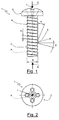
- the number 1 refers to a reversible pressure pin in its entirety.
- the pin 1 is made of plastic material, and comprises a stem 2 which presents a longitudinal axis A, an end head 3 which is integral with the stem 2, and a spiral thread 4, which extends along the stem 2 itself, and which comprises, in turn, an outer placement surface 5 which is inclined at an angle ⁇ which is substantially equal to 24° in relation to the axis A and in a placement direction G of the pin 1 itself.
- the thread 4 comprises an outer extraction surface 6 which is inclined at an angle ⁇ which is substantially equal to 85° in relation to the axis A and in an extraction direction E of the pin 1 itself opposite and parallel to the placement direction G.
- the thread 4 presents:
- the end head 3 is provided with an upper indentation (impronta) 7, and presents an outer diameter of dimensions which are less than the double of the dimensions of the outer nominal diameter ⁇ , while the stem 2 presents a minimal length which is equal to 1.8 of the dimensions of the diameter ⁇ .
- pin 1 which has been described above is particularly advantageous in all those applications in which, once the pin 1 has been placed inside a respective cylindrical housing, which is preferably made of material of a yielding kind, it is necessary to provide for the rapid removal of the pin 1 itself so that it is possible to permit maintenance operations or the replacement of assembled components by means of the pin 1.
Landscapes
- Engineering & Computer Science (AREA)
- General Engineering & Computer Science (AREA)
- Mechanical Engineering (AREA)
- Orthopedics, Nursing, And Contraception (AREA)
- Containers And Packaging Bodies Having A Special Means To Remove Contents (AREA)
Applications Claiming Priority (2)
| Application Number | Priority Date | Filing Date | Title |
|---|---|---|---|
| ITTO20030757 ITTO20030757A1 (it) | 2003-09-30 | 2003-09-30 | Perno a pressione reversibile. |
| ITTO20030757 | 2003-09-30 |
Publications (2)
| Publication Number | Publication Date |
|---|---|
| EP1520997A2 true EP1520997A2 (de) | 2005-04-06 |
| EP1520997A3 EP1520997A3 (de) | 2006-04-19 |
Family
ID=34308157
Family Applications (1)
| Application Number | Title | Priority Date | Filing Date |
|---|---|---|---|
| EP04023151A Withdrawn EP1520997A3 (de) | 2003-09-30 | 2004-09-29 | Lösbarer Druckstiftbolzen |
Country Status (2)
| Country | Link |
|---|---|
| EP (1) | EP1520997A3 (de) |
| IT (1) | ITTO20030757A1 (de) |
Family Cites Families (5)
| Publication number | Priority date | Publication date | Assignee | Title |
|---|---|---|---|---|
| DE2501942A1 (de) * | 1975-01-18 | 1976-07-22 | Textron Inc | Einschiebbares gewinde-befestigungselement |
| DE2644215C2 (de) * | 1976-09-30 | 1983-08-18 | Agfa-Gevaert Ag, 5090 Leverkusen | Schraube |
| DE3674584D1 (de) * | 1986-05-02 | 1990-10-31 | Rasmussen Kann Ind As | Einschlagschraube. |
| DE29720795U1 (de) * | 1997-11-24 | 1999-04-01 | Joh. Friedrich Behrens AG, 22926 Ahrensburg | Nagelschraube |
| JP2000320516A (ja) * | 1999-05-14 | 2000-11-24 | Hiroki Kanai | スクリュー釘 |
-
2003
- 2003-09-30 IT ITTO20030757 patent/ITTO20030757A1/it unknown
-
2004
- 2004-09-29 EP EP04023151A patent/EP1520997A3/de not_active Withdrawn
Also Published As
| Publication number | Publication date |
|---|---|
| EP1520997A3 (de) | 2006-04-19 |
| ITTO20030757A1 (it) | 2005-04-01 |
Similar Documents
| Publication | Publication Date | Title |
|---|---|---|
| KR101215012B1 (ko) | 뼈 고정 요소 | |
| ES2390734T3 (es) | Elemento para introducir a presión en un componente constructivo no perforado o preperforado, así como procedimiento para la fabricación de un elemento para introducir a presión | |
| US6800078B2 (en) | Orthopedic stabilization device and method | |
| CN104546105B (zh) | 具有自约束挠性的骨螺钉 | |
| DK2177783T3 (en) | Gas spring safety device | |
| US20030176861A1 (en) | Orthopedic stabilization device and method | |
| EP2666436A1 (de) | Orthodontisches verbindungswerkzeug | |
| EP1997450A1 (de) | Knochen-Verankerungselement | |
| JP5895648B2 (ja) | ヘッド交換式切削工具 | |
| EP2267820A3 (de) | Elektrodenwickel | |
| ES2626142T3 (es) | Proyectil con casquillo desprendible | |
| EP2463623A3 (de) | Hemisphärisches Resonatorgyroskop mit verteilten Massen | |
| EP2492520A3 (de) | Befestigungsstift und Herstellungsverfahren dafür | |
| US880534A (en) | Repair-tip for umbrellas. | |
| EP2025955A3 (de) | Gewindebolzen und Verfahren zu seiner Herstellung | |
| EP2261519A3 (de) | Schraube zum Befestigen eines ersten Bauteils an einem zweiten Bauteil | |
| CA2601152A1 (en) | Box end sucker rod shear coupling | |
| US10004570B2 (en) | Assembly comprising a component and an axial limit stop device intended to be placed in a bore of said component | |
| US7320570B2 (en) | Set screw with NiTi tip | |
| EP2724682A1 (de) | Rückhaltesystem für ein Befestigungsmittel | |
| CN107007322A (zh) | 用于骨板的仪器引导组件以及骨板与这种仪器引导组件的套件 | |
| EP2913568A1 (de) | Ventil mit mindestens einem sanduhrform-bolzen zur ankopplung an eine membran und verdichter-/spindelkomponenten | |
| EP3130248A1 (de) | Keramische uhrkette | |
| JP2022506812A5 (de) | ||
| EP1750355A3 (de) | Spulenwickel- und Entladevorrichtung |
Legal Events
| Date | Code | Title | Description |
|---|---|---|---|
| PUAI | Public reference made under article 153(3) epc to a published international application that has entered the european phase |
Free format text: ORIGINAL CODE: 0009012 |
|
| AK | Designated contracting states |
Kind code of ref document: A2 Designated state(s): AT BE BG CH CY CZ DE DK EE ES FI FR GB GR HU IE IT LI LU MC NL PL PT RO SE SI SK TR |
|
| AX | Request for extension of the european patent |
Extension state: AL HR LT LV MK |
|
| PUAL | Search report despatched |
Free format text: ORIGINAL CODE: 0009013 |
|
| AK | Designated contracting states |
Kind code of ref document: A3 Designated state(s): AT BE BG CH CY CZ DE DK EE ES FI FR GB GR HU IE IT LI LU MC NL PL PT RO SE SI SK TR |
|
| AX | Request for extension of the european patent |
Extension state: AL HR LT LV MK |
|
| RIC1 | Information provided on ipc code assigned before grant |
Ipc: F16B 15/06 20060101ALI20060302BHEP Ipc: F16B 37/04 20060101ALI20060302BHEP Ipc: F16B 21/07 20060101AFI20050117BHEP |
|
| 17P | Request for examination filed |
Effective date: 20061018 |
|
| AKX | Designation fees paid |
Designated state(s): AT BE BG CH CY CZ DE DK EE ES FI FR GB GR HU IE IT LI LU MC NL PL PT RO SE SI SK TR |
|
| 17Q | First examination report despatched |
Effective date: 20100820 |
|
| STAA | Information on the status of an ep patent application or granted ep patent |
Free format text: STATUS: THE APPLICATION IS DEEMED TO BE WITHDRAWN |
|
| 18D | Application deemed to be withdrawn |
Effective date: 20101231 |