EP1520997A2 - Releasable pressure pin - Google Patents
Releasable pressure pin Download PDFInfo
- Publication number
- EP1520997A2 EP1520997A2 EP04023151A EP04023151A EP1520997A2 EP 1520997 A2 EP1520997 A2 EP 1520997A2 EP 04023151 A EP04023151 A EP 04023151A EP 04023151 A EP04023151 A EP 04023151A EP 1520997 A2 EP1520997 A2 EP 1520997A2
- Authority
- EP
- European Patent Office
- Prior art keywords
- dimensions
- pressure pin
- stem
- fact
- presents
- Prior art date
- Legal status (The legal status is an assumption and is not a legal conclusion. Google has not performed a legal analysis and makes no representation as to the accuracy of the status listed.)
- Withdrawn
Links
Images
Classifications
-
- F—MECHANICAL ENGINEERING; LIGHTING; HEATING; WEAPONS; BLASTING
- F16—ENGINEERING ELEMENTS AND UNITS; GENERAL MEASURES FOR PRODUCING AND MAINTAINING EFFECTIVE FUNCTIONING OF MACHINES OR INSTALLATIONS; THERMAL INSULATION IN GENERAL
- F16B—DEVICES FOR FASTENING OR SECURING CONSTRUCTIONAL ELEMENTS OR MACHINE PARTS TOGETHER, e.g. NAILS, BOLTS, CIRCLIPS, CLAMPS, CLIPS OR WEDGES; JOINTS OR JOINTING
- F16B15/00—Nails; Staples
- F16B15/06—Nails; Staples with barbs, e.g. for metal parts; Drive screws
Definitions
- the present invention refers to a reversible pressure pin.
- pressure pins are well known, which are suitable for being pressure inserted inside a cylindrical housing, and they comprise a stem which presents a longitudinal axis, an end head which is integral with the stem, and a number of conical projections which are arranged one after the other along the stem and transverse to the axis.
- Pins of the type which have just been described above present a disadvantage, in that it is impossible to remove the pins themselves easily once they have been placed.
- the aim of the present invention is to produce a reversible pressure pin, which will be free of the above-described disadvantage.
- a reversible pressure pin comprising a stem presenting a longitudinal axis, and an end head which is integral with the stem; the pin being characterised by the fact that it comprises a spiral thread which extends along the stem, and presents an outer placement surface which is inclined at an angle which is substantially equal to 24° in relation to the axis and in a placement direction of the pin itself.
- the number 1 refers to a reversible pressure pin in its entirety.
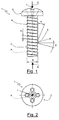
- the pin 1 is made of plastic material, and comprises a stem 2 which presents a longitudinal axis A, an end head 3 which is integral with the stem 2, and a spiral thread 4, which extends along the stem 2 itself, and which comprises, in turn, an outer placement surface 5 which is inclined at an angle ⁇ which is substantially equal to 24° in relation to the axis A and in a placement direction G of the pin 1 itself.
- the thread 4 comprises an outer extraction surface 6 which is inclined at an angle ⁇ which is substantially equal to 85° in relation to the axis A and in an extraction direction E of the pin 1 itself opposite and parallel to the placement direction G.
- the thread 4 presents:
- the end head 3 is provided with an upper indentation (impronta) 7, and presents an outer diameter of dimensions which are less than the double of the dimensions of the outer nominal diameter ⁇ , while the stem 2 presents a minimal length which is equal to 1.8 of the dimensions of the diameter ⁇ .
- pin 1 which has been described above is particularly advantageous in all those applications in which, once the pin 1 has been placed inside a respective cylindrical housing, which is preferably made of material of a yielding kind, it is necessary to provide for the rapid removal of the pin 1 itself so that it is possible to permit maintenance operations or the replacement of assembled components by means of the pin 1.
Landscapes
- Engineering & Computer Science (AREA)
- General Engineering & Computer Science (AREA)
- Mechanical Engineering (AREA)
- Orthopedics, Nursing, And Contraception (AREA)
- Containers And Packaging Bodies Having A Special Means To Remove Contents (AREA)
Abstract
Description
- FIGURE 1 is a lateral elevation view of a preferred form of embodiment of the pin according to the present invention; and
- FIGURE 2 is a view from above of the pin which is illustrated in FIGURE 1.
- an outer nominal diameter Φ which is of determined dimensions, and a lead angle P which is of dimensions which are substantially equal to 1/3.6 of the dimensions of the outer nominal diameter Φ itself; and
- an internal diameter N which is inside the outer nominal diameter Φ, and which is of dimensions such that the difference between the diameter Φ and a dimension of the diameter N is equal to 1/2.5 of the dimensions of the lead angle P.
Claims (7)
- Reversible pressure pin (1) comprising a stem (2) presenting a longitudinal axis (A), and an end head (3) which is integral with the stem (2); the pin (1) being characterised by the fact that it comprises a spiral thread (4) which extends along the stem (2), and presents an outer placement surface (5) which is inclined at an angle which is substantially equal to 24° in relation to the axis (A) and in a placement direction (G) of the pin (1) itself.
- Pressure pin according to Claim 1, characterised by the fact that the spiral thread (4) comprises an outer extraction surface (6) which is inclined at an angle which is substantially equal to 85° in relation to the axis (A) and in an extraction direction (E) of the pin (1) itself opposite and parallel to the placement direction (G).
- Pressure pin according to Claim 2, characterised by the fact that the said thread (4) presents an outer nominal diameter (Φ) which is of determined dimensions, and a lead angle (P) which is of dimensions which are substantially equal to 1/3.6 of the dimensions of the outer nominal diameter (Φ) itself.
- Pressure pin according to Claims 2 or 3, characterised by the fact that the said thread (4) presents an internal diameter (N) inside the said outer nominal diameter (Φ); the difference between the dimension of the said outer nominal diameter (Φ) and a dimension of the internal diameter (N) being substantially equal to 1/2.5 of the dimensions of the lead angle (P).
- Pressure pin according to Claim 3, characterised by the fact that the said end head (3) presents an outer diameter which is of dimensions which are less than the double of the dimensions of the said outer nominal diameter (Φ).
- Pressure pin according to Claim 3, characterised by the fact that the said stem (2) presents a minimal length which is equal to 1.8 of the dimensions of the outer nominal diameter (Φ).
- Pressure pin according to any of the preceding Claims whatsoever, characterised by the fact that it is made of plastic material.
Applications Claiming Priority (2)
| Application Number | Priority Date | Filing Date | Title |
|---|---|---|---|
| ITTO20030757 ITTO20030757A1 (en) | 2003-09-30 | 2003-09-30 | REVERSIBLE PRESSURE PIN. |
| ITTO20030757 | 2003-09-30 |
Publications (2)
| Publication Number | Publication Date |
|---|---|
| EP1520997A2 true EP1520997A2 (en) | 2005-04-06 |
| EP1520997A3 EP1520997A3 (en) | 2006-04-19 |
Family
ID=34308157
Family Applications (1)
| Application Number | Title | Priority Date | Filing Date |
|---|---|---|---|
| EP04023151A Withdrawn EP1520997A3 (en) | 2003-09-30 | 2004-09-29 | Releasable pressure pin |
Country Status (2)
| Country | Link |
|---|---|
| EP (1) | EP1520997A3 (en) |
| IT (1) | ITTO20030757A1 (en) |
Family Cites Families (5)
| Publication number | Priority date | Publication date | Assignee | Title |
|---|---|---|---|---|
| DE2501942A1 (en) * | 1975-01-18 | 1976-07-22 | Textron Inc | Self-tapping screw for use with plastic materials - needs only one sixth turn to be fully tightened |
| DE2644215C2 (en) * | 1976-09-30 | 1983-08-18 | Agfa-Gevaert Ag, 5090 Leverkusen | screw |
| DE3674584D1 (en) * | 1986-05-02 | 1990-10-31 | Rasmussen Kann Ind As | IMPACT SCREW. |
| DE29720795U1 (en) * | 1997-11-24 | 1999-04-01 | Joh. Friedrich Behrens AG, 22926 Ahrensburg | Nail screw |
| JP2000320516A (en) * | 1999-05-14 | 2000-11-24 | Hiroki Kanai | Screw nail |
-
2003
- 2003-09-30 IT ITTO20030757 patent/ITTO20030757A1/en unknown
-
2004
- 2004-09-29 EP EP04023151A patent/EP1520997A3/en not_active Withdrawn
Also Published As
| Publication number | Publication date |
|---|---|
| EP1520997A3 (en) | 2006-04-19 |
| ITTO20030757A1 (en) | 2005-04-01 |
Similar Documents
| Publication | Publication Date | Title |
|---|---|---|
| KR101215012B1 (en) | Bone Anchoring Element | |
| ES2390734T3 (en) | Element for pressure insertion in a non-perforated or pre-drilled construction component, as well as a method for manufacturing an element for pressure insertion | |
| US6800078B2 (en) | Orthopedic stabilization device and method | |
| CN104546105B (en) | With self-constrained flexible bone screws | |
| DK2177783T3 (en) | Gas spring safety device | |
| US20030176861A1 (en) | Orthopedic stabilization device and method | |
| EP2666436A1 (en) | Orthodontic connection tool | |
| EP1997450A1 (en) | Bone anchoring element | |
| JP5895648B2 (en) | Replaceable head cutting tool | |
| EP2267820A3 (en) | Electrode coil | |
| ES2626142T3 (en) | Projectile with removable bushing | |
| EP2463623A3 (en) | Distributed mass hemispherical resonator gyroscope | |
| EP2492520A3 (en) | Fastening pin and manufacturing method thereof | |
| US880534A (en) | Repair-tip for umbrellas. | |
| EP2025955A3 (en) | Threaded bolt and method for its production | |
| EP2261519A3 (en) | Screw for attaching one component to a second component | |
| CA2601152A1 (en) | Box end sucker rod shear coupling | |
| US10004570B2 (en) | Assembly comprising a component and an axial limit stop device intended to be placed in a bore of said component | |
| US7320570B2 (en) | Set screw with NiTi tip | |
| EP2724682A1 (en) | Fastener retention system | |
| CN107007322A (en) | External member for the instrument guide assembly and hone lamella and this instrument guide assembly of hone lamella | |
| EP2913568A1 (en) | Valve having at least one hourglass stud for coupling to diaphragm and compressor/spindle components | |
| EP3130248A1 (en) | Ceramic watch chain | |
| JP2022506812A5 (en) | ||
| EP1750355A3 (en) | Coil winding and discharge |
Legal Events
| Date | Code | Title | Description |
|---|---|---|---|
| PUAI | Public reference made under article 153(3) epc to a published international application that has entered the european phase |
Free format text: ORIGINAL CODE: 0009012 |
|
| AK | Designated contracting states |
Kind code of ref document: A2 Designated state(s): AT BE BG CH CY CZ DE DK EE ES FI FR GB GR HU IE IT LI LU MC NL PL PT RO SE SI SK TR |
|
| AX | Request for extension of the european patent |
Extension state: AL HR LT LV MK |
|
| PUAL | Search report despatched |
Free format text: ORIGINAL CODE: 0009013 |
|
| AK | Designated contracting states |
Kind code of ref document: A3 Designated state(s): AT BE BG CH CY CZ DE DK EE ES FI FR GB GR HU IE IT LI LU MC NL PL PT RO SE SI SK TR |
|
| AX | Request for extension of the european patent |
Extension state: AL HR LT LV MK |
|
| RIC1 | Information provided on ipc code assigned before grant |
Ipc: F16B 15/06 20060101ALI20060302BHEP Ipc: F16B 37/04 20060101ALI20060302BHEP Ipc: F16B 21/07 20060101AFI20050117BHEP |
|
| 17P | Request for examination filed |
Effective date: 20061018 |
|
| AKX | Designation fees paid |
Designated state(s): AT BE BG CH CY CZ DE DK EE ES FI FR GB GR HU IE IT LI LU MC NL PL PT RO SE SI SK TR |
|
| 17Q | First examination report despatched |
Effective date: 20100820 |
|
| STAA | Information on the status of an ep patent application or granted ep patent |
Free format text: STATUS: THE APPLICATION IS DEEMED TO BE WITHDRAWN |
|
| 18D | Application deemed to be withdrawn |
Effective date: 20101231 |