EP1520895B1 - A method for securing a component - Google Patents
A method for securing a component Download PDFInfo
- Publication number
- EP1520895B1 EP1520895B1 EP03022314A EP03022314A EP1520895B1 EP 1520895 B1 EP1520895 B1 EP 1520895B1 EP 03022314 A EP03022314 A EP 03022314A EP 03022314 A EP03022314 A EP 03022314A EP 1520895 B1 EP1520895 B1 EP 1520895B1
- Authority
- EP
- European Patent Office
- Prior art keywords
- component
- laminate
- sheet
- border
- stiffness
- Prior art date
- Legal status (The legal status is an assumption and is not a legal conclusion. Google has not performed a legal analysis and makes no representation as to the accuracy of the status listed.)
- Expired - Lifetime
Links
- 238000000034 method Methods 0.000 title claims abstract description 43
- 239000000835 fiber Substances 0.000 claims abstract description 26
- 239000002131 composite material Substances 0.000 claims abstract description 24
- 238000010276 construction Methods 0.000 claims description 15
- 239000000463 material Substances 0.000 claims description 12
- 238000004026 adhesive bonding Methods 0.000 claims description 10
- 239000004411 aluminium Substances 0.000 claims description 10
- 229910052782 aluminium Inorganic materials 0.000 claims description 10
- XAGFODPZIPBFFR-UHFFFAOYSA-N aluminium Chemical compound [Al] XAGFODPZIPBFFR-UHFFFAOYSA-N 0.000 claims description 10
- 229910052751 metal Inorganic materials 0.000 claims description 9
- 239000002184 metal Substances 0.000 claims description 9
- OKTJSMMVPCPJKN-UHFFFAOYSA-N Carbon Chemical compound [C] OKTJSMMVPCPJKN-UHFFFAOYSA-N 0.000 claims description 8
- 229910052799 carbon Inorganic materials 0.000 claims description 8
- 239000011159 matrix material Substances 0.000 claims description 8
- 229910001374 Invar Inorganic materials 0.000 claims description 5
- 239000004593 Epoxy Substances 0.000 claims description 4
- 229910000831 Steel Inorganic materials 0.000 claims description 3
- RTAQQCXQSZGOHL-UHFFFAOYSA-N Titanium Chemical compound [Ti] RTAQQCXQSZGOHL-UHFFFAOYSA-N 0.000 claims description 3
- 230000002787 reinforcement Effects 0.000 claims description 3
- 239000010959 steel Substances 0.000 claims description 3
- 239000003365 glass fiber Substances 0.000 claims description 2
- 229920000728 polyester Polymers 0.000 claims description 2
- 239000000853 adhesive Substances 0.000 description 17
- 230000001070 adhesive effect Effects 0.000 description 17
- 229920000271 Kevlar® Polymers 0.000 description 1
- 239000000956 alloy Substances 0.000 description 1
- 229910045601 alloy Inorganic materials 0.000 description 1
- 239000011162 core material Substances 0.000 description 1
- 230000006378 damage Effects 0.000 description 1
- 230000001419 dependent effect Effects 0.000 description 1
- 239000004761 kevlar Substances 0.000 description 1
- 238000004519 manufacturing process Methods 0.000 description 1
- 238000012986 modification Methods 0.000 description 1
- 230000004048 modification Effects 0.000 description 1
- 239000011347 resin Substances 0.000 description 1
- 229920005989 resin Polymers 0.000 description 1
Images
Classifications
-
- F—MECHANICAL ENGINEERING; LIGHTING; HEATING; WEAPONS; BLASTING
- F16—ENGINEERING ELEMENTS AND UNITS; GENERAL MEASURES FOR PRODUCING AND MAINTAINING EFFECTIVE FUNCTIONING OF MACHINES OR INSTALLATIONS; THERMAL INSULATION IN GENERAL
- F16B—DEVICES FOR FASTENING OR SECURING CONSTRUCTIONAL ELEMENTS OR MACHINE PARTS TOGETHER, e.g. NAILS, BOLTS, CIRCLIPS, CLAMPS, CLIPS OR WEDGES; JOINTS OR JOINTING
- F16B11/00—Connecting constructional elements or machine parts by sticking or pressing them together, e.g. cold pressure welding
- F16B11/006—Connecting constructional elements or machine parts by sticking or pressing them together, e.g. cold pressure welding by gluing
-
- B—PERFORMING OPERATIONS; TRANSPORTING
- B64—AIRCRAFT; AVIATION; COSMONAUTICS
- B64C—AEROPLANES; HELICOPTERS
- B64C1/00—Fuselages; Constructional features common to fuselages, wings, stabilising surfaces or the like
- B64C2001/0054—Fuselage structures substantially made from particular materials
- B64C2001/0072—Fuselage structures substantially made from particular materials from composite materials
-
- F—MECHANICAL ENGINEERING; LIGHTING; HEATING; WEAPONS; BLASTING
- F16—ENGINEERING ELEMENTS AND UNITS; GENERAL MEASURES FOR PRODUCING AND MAINTAINING EFFECTIVE FUNCTIONING OF MACHINES OR INSTALLATIONS; THERMAL INSULATION IN GENERAL
- F16B—DEVICES FOR FASTENING OR SECURING CONSTRUCTIONAL ELEMENTS OR MACHINE PARTS TOGETHER, e.g. NAILS, BOLTS, CIRCLIPS, CLAMPS, CLIPS OR WEDGES; JOINTS OR JOINTING
- F16B19/00—Bolts without screw-thread; Pins, including deformable elements; Rivets
- F16B19/04—Rivets; Spigots or the like fastened by riveting
- F16B19/06—Solid rivets made in one piece
-
- Y—GENERAL TAGGING OF NEW TECHNOLOGICAL DEVELOPMENTS; GENERAL TAGGING OF CROSS-SECTIONAL TECHNOLOGIES SPANNING OVER SEVERAL SECTIONS OF THE IPC; TECHNICAL SUBJECTS COVERED BY FORMER USPC CROSS-REFERENCE ART COLLECTIONS [XRACs] AND DIGESTS
- Y02—TECHNOLOGIES OR APPLICATIONS FOR MITIGATION OR ADAPTATION AGAINST CLIMATE CHANGE
- Y02T—CLIMATE CHANGE MITIGATION TECHNOLOGIES RELATED TO TRANSPORTATION
- Y02T50/00—Aeronautics or air transport
- Y02T50/40—Weight reduction
Definitions
- the present invention relates to a method for securing a component having a high stiffness to a fibre composite laminate by adhesive bonding.
- High stiffness means in this disclosure that the component or part is of a stiff nature, but it may have a lower modulus of elasticity than another component here being considered to have a low stiffness, since it is thinner than the first one. The same reasoning is valid for "lower stiffness". Accordingly, said component to be secured may be of a material having a lower modulus of elasticity than the fibre composite laminate but still have a high sitffness, when it is thick enough.
- the fibre composite laminate may be of any known type, and such laminates are composed by a number of superimposed thin layers, each constituted by substantially parallel fibres embedded in a matrix, glued to each other for obtaining a body having a very high stiffness in relation to the weight thereof.
- the fibre composite laminate may also have a very high strength in relation to the weight thereof, but only in one direction of each layer. They are, however, comparatively weak and have a low stiffness in the direction transversal to the fibre direction.
- the layers are for that sake arranged with different fibre directions so as to obtain good properties in two dimensions. However, the properties will remain bad in the third direction (out of the plane of a sheet of such layers).
- the layers are arranged with different fibre directions for giving the laminate a strength being appropriate for each individual application.
- the layers may for instance be arranged for giving the laminate a strength being substantially uniform in said two dimensions, but they are often arranged so as to make the laminate stiffer in some direction than in another.
- fibre composite laminates are particularly interesting where a combination of a low weight and a high stiffness and strength is important, such as in space.
- US-S-4966802 relates to composites made of fibre reinforced resin elements joined by adhesive.
- US-A-4556592 concerns conductive joint seals for composite aircraft.
- the object of the present invention is to provide a method of the type defined in the introduction, which solves the problems discussed above to a large extent.
- This object is according to the invention obtained by providing such a method, in which a sheet having a substantially lower stiffness than the stiffness of the component is interposed between the component and the laminate so that the sheet extends and has its border substantially beyond the border of the component where the border of the latter is located in overlap with the laminate, and the sheet is affixed by adhesive bonding to the laminate as well as the component for securing them to each other.
- the component is secured to the laminate through said sheet having a substantially lower stiffness than the stiffness of the component.
- a sheet may without any problems be produced and adhesively bonded to the laminate, and the component may be manufactured without using any delicate process steps. Concentrations of shear and tension forces in the adhesive joint between the component and the sheet will be transferred to the adhesive joint between the sheet and the laminate at the border of the sheet while reducing these forces.
- substantially lower stiffness is to be interpreted as explained in the introduction. It does not necessarily mean that said sheet has a lower modulus of elasticity than the material of the component but this may even be higher and the thickness of the sheet then considerably lower. Furthermore, thanks to this substantially lower stiffness of said sheet it is efficiently avoided to introduce considerably higher load into a laminate layer than this may withstand. Accordingly, upon application of high loads the adhesive joint will rather break than the laminate, such as carbon fibres, in the laminate layer close to the sheet, which would result in a destruction of this laminate layer.
- it is a said sheet having a stiffness in the same order of magnitude as the stiffness of a laminate layer to which it is adhesively bonded that is interposed between the component and the laminate. This means that there will be no risk of introducing considerably higher loads into a laminate layer than this may withstand.
- the component is a component made of a metal that is secured to the fibre composite laminate, said metal preferably being aluminium, and it is a sheet of metal that is interposed between the component and the laminate.
- the experience and the knowledge within the field of adhesively bonding metal to metal is very broad, so that it will in such a case be comparatively easy to efficiently adhesively bond the component to said sheet.
- the component must not necessarily be made of metal.
- it is a sheet of a material having substantially the same coefficient of thermal expansion as said laminate that is interposed between the component and the laminate.
- a laminate has a coefficient of thermal expansion being very low, which means that the laminate will have substantially the same dimensions even if the temperature thereof would vary substantially.
- aluminium has a coefficient of thermal expansion being much higher, which means that shear and tension forces are introduced into the adhesive joint between a component of aluminium and a fibre composite laminate if these are adhesively bonded to each other.
- said component is secured to a laminate having a plurality of layers, each layer having substantially parallel carbon fibres embedded in a matrix, preferably an epoxy matrix.
- the method according to the invention is particularly well applicable to securing a component to such a laminate by adhesive bonding, since such a laminate has an optimum combination of weight and stiffness for being used in space, to which it then is for weight reasons preferred to secure components of aluminium resulting in the problems discussed above, but solved through the method according to the invention.
- a plurality of said sheets are superimposed and adhesively bonded to each other and interposed between the component and the laminate as a package, and the outer sheets of said package are adhesively bonded to the component and the laminate, respectively, so that for adjacent sheets said border of the sheet closest to the component is located at a shorter distance to said border of the component than said border of the other sheet.
- An alternative to this, which constitutes a further preferred embodiment of the invention, is to adhesively bond a sheet having a thickness being stepwisely reduced between said border of the component and said border of the sheet to the laminate and the component.
- the component is secured to a laminate forming a cover of reinforcement of a sandwich construction and the sheet is adhesively bonded to the laminate in the same step as the sandwich construction is cured.
- sandwich constructions are very advantageous for the use in space, since they constitute a construction being optimum from the weight point of view.
- the method is carried out as a part of a process for producing a product to be used in space. Advantages of such a method appear from the discussion above.
- a component 1 of for example aluminium having a high stiffness is adhesively bonded through an adhesive joint 2 to a fibre composite laminate 3.
- This laminate is composed by a plurality of superimposed layers 4 each having substantially parallel fibres embedded in a matrix.
- a typical thickness of such a layer 4 is 0.1-0.3 mm.
- the material of these layers may for instance be carbon fibres embedded in an epoxy matrix, glass fibres embedded in a polyester matrix or kevlar fibres embedded in a matrix. Concentrations of shear and tension forces in the adhesive joint will appear at the border 5 of the component where the border of the latter is located in overlap with the laminate. Such concentrations reduce the possibility to introduce load into the laminate in the same order of magnitude as the load for which the laminate is dimensioned. Furthermore, a substantial difference of the coefficient of thermal expansion of the material of the component with respect to the material of the laminate 3 results in a risk of introducing stresses destroying the adhesive joint or the laminate layer closest thereto when the temperature is changed substantially.
- a method for securing a component having a high stiffness to a fibre composite laminate by adhesive bonding according to the invention is illustrated through Figs 2 and 3 .
- the component 1 is here secured to a laminate 3', 3" forming a cover of reinforcement of a sandwich construction 13 on the respective side of an intermediate core material 6 of a comparatively low stiffness and strength. It is illustrated how a sheet 7 having, thanks to a much lower thickness than the thickness of the component 1, a substantially lower stiffness than the stiffness of the component is interposed between the component and the laminate so that the sheet extends and has its border 8 substantially beyond the border 5 of the component where the border of the latter is located in overlap with the laminate.
- the sheet is affixed by adhesively bonding to the laminate as well as to the component for securing them to each other.
- the distance between the border 8 of the sheet and that 5 of the component may typically be in the order of 2-8 mm.
- the sheet may typically have a thickness of 0.5-2 mm.
- the sheet 7 has preferably a stiffness in the same order of magnitude as the stiffness of a laminate layer to which it is adhesively bonded, which means that it is avoided to introduce considerably higher loads into the laminate layer than it may withstand. Furthermore, concentrations of shear and tension forces at the end of the adhesive joint at 5 are transferred to the sheet 7 and results in lower shear and tension forces in the region of the border 8.
- the sheet is preferably adhesively bonded to the sandwich construction in the same step as this is cured under high temperatures and pressures in a so-called autoclave.
- the low thickness of the sheet 7 makes it possible to handle it as if it would be a prepreg piece easy to handle.
- the sheet shall accordingly have a substantially lower stiffness than the stiffness of the component, and have substantially the same coefficient of thermal expansion as the laminate.
- Steel, titan or invar are preferred materials for the sheet in the case of a laminate of carbon fibre epoxy. Invar appears to be most preferred with respect to the coefficient of thermal expansion being nearly zero, especially when the Ni portion thereof is about 36 percent by weight.
- a component 1 of aluminium or another metal may be affixed by adhesive bonding through traditional adhesive joints and methods.
- Fig 4 illustrates how a plurality of said sheets 7', 7", 7"' are superimposed and adhesively bonded to each other and interposed between the component and the laminate as a package according to another preferred embodiment of the method according to the invention.
- the outer sheets 7', 7'" of said package are adhesively bonded to the component and the laminate, respectively, so that for adjacent sheets said border 8', 8" of the sheet closest to the component is located at a shorter distance to said border 5 of the component than said border 8", 8"' of the other sheet.
- the concentration of shear and tension forces at the border of the adhesive joint between the component and the sheet is by this reduced at each step so formed for making these forces low in the adhesive joint between the sheet 8"' and the laminate 3.
- Fig 2 It is shown in Fig 2 how the component is secured to the laminate close to a border 9 thereof so that is projects beyond the border of the laminate. A preferred way to proceed in such a case is illustrated in Fig 5 . It is shown how a sheet 7 is adhesively bonded to the laminate 3 so that a portion 10 thereof will be located in the region near said border 9 of the laminate, so that the component 1 is adhesively bonded to a surface of the sheet ending at a distance from said border of the laminate. This means that concentration of shear and tension forces at the adhesive joint border 11 between the component and the sheet will be distributed over a larger area and result in lower shear and tension forces next to the laminate at the border 9.
- the sheet (7) may be adhesively bonded to the laminate (3) so that a portion (10) thereof with a reduced thickness with respect to the rest of the sheet will be located in the region near said border (9) of the laminate, so that the component is adhesively bonded to a surface of the sheet ending at a distance from said border of the laminate.
- the invention is not restricted to the order of adhesively bonding the different pieces to each other described above, but this order may be different, so that the component may be adhesively bonded to said sheet simultaneously as the sheet is adhesively bonded to the laminate.
- the component may be adhesively bonded to a surface portion of the laminate distant from any border of the laminate.
- the lower stiffness of the sheet than of the component is preferably obtained by using a lower thickness for the former, such as less than 1 ⁇ 2 or 1 ⁇ 4 of the thickness of the component.
- a lower thickness for the former such as less than 1 ⁇ 2 or 1 ⁇ 4 of the thickness of the component.
Landscapes
- Engineering & Computer Science (AREA)
- General Engineering & Computer Science (AREA)
- Mechanical Engineering (AREA)
- Laminated Bodies (AREA)
- Standing Axle, Rod, Or Tube Structures Coupled By Welding, Adhesion, Or Deposition (AREA)
- Processing Of Terminals (AREA)
- Mechanical Coupling Of Light Guides (AREA)
- Pressure Welding/Diffusion-Bonding (AREA)
Abstract
Description
- The present invention relates to a method for securing a component having a high stiffness to a fibre composite laminate by adhesive bonding.
- "High stiffness" means in this disclosure that the component or part is of a stiff nature, but it may have a lower modulus of elasticity than another component here being considered to have a low stiffness, since it is thinner than the first one. The same reasoning is valid for "lower stiffness". Accordingly, said component to be secured may be of a material having a lower modulus of elasticity than the fibre composite laminate but still have a high sitffness, when it is thick enough.
- The fibre composite laminate may be of any known type, and such laminates are composed by a number of superimposed thin layers, each constituted by substantially parallel fibres embedded in a matrix, glued to each other for obtaining a body having a very high stiffness in relation to the weight thereof. The fibre composite laminate may also have a very high strength in relation to the weight thereof, but only in one direction of each layer. They are, however, comparatively weak and have a low stiffness in the direction transversal to the fibre direction. The layers are for that sake arranged with different fibre directions so as to obtain good properties in two dimensions. However, the properties will remain bad in the third direction (out of the plane of a sheet of such layers). This constitutes a problem in adhesive joints, which create a load on the laminate acting out of the plane of the laminate. The layers are arranged with different fibre directions for giving the laminate a strength being appropriate for each individual application. The layers may for instance be arranged for giving the laminate a strength being substantially uniform in said two dimensions, but they are often arranged so as to make the laminate stiffer in some direction than in another.
- The use of such fibre composite laminates is particularly interesting where a combination of a low weight and a high stiffness and strength is important, such as in space.
- There are certain problems to secure a component having a high stiffness to such a fibre composite laminate by adhesive bonding, and although these problems are in common for all such fibre composite laminates and components having a high stiffness these problems will now be described for the case of securing a component of aluminium to a carbon fibre composite laminate by adhesive bonding for illuminating the problems to be solved by the invention but not in any way limiting the invention thereto.
- Due to the fragile character of the carbon fibre composite laminate the introductions of loads has to be carried out very carefully. Concentrations of tension and shear forces in the adhesive joint between the component and the laminate may not be avoided in spite of the good capacity of the adhesive joint to distribute the load over a large area. These concentrations of shear and tension forces occur at the border of the component, accordingly, where the overlap of the component ends. These concentrations of shear and tension forces reduce the possibility to introduce load in the same order of magnitude as the maximum load for which the laminate is dimensioned, since the laminate would then break.
- It has been suggested to reduce the thickness of such components of aluminium considerably close to the border thereof to be located on the laminate after the securing thereto so as to solve the problems mentioned above. This would then result in a lower stiffness of that part of the component making the concentrations of shear and tension forces not that critical any longer. It would also be avoided to introduce higher loads into one layer of the laminate than this may withstand. However, this solution normally, although it is occasionally used, does not constitute any real option, since the extremely thin portions of the aluminium components are very difficult to manufacture and handle.
- Daniel Gay: "Materiaux Composites" 1991, Hermis, Paris ISBN: 2-86601-116-3 page 166 and
WO 02/42152 A -
US-S-4966802 relates to composites made of fibre reinforced resin elements joined by adhesive. -
US-A-4556592 concerns conductive joint seals for composite aircraft. - The object of the present invention is to provide a method of the type defined in the introduction, which solves the problems discussed above to a large extent.
- This object is according to the invention obtained by providing such a method, in which a sheet having a substantially lower stiffness than the stiffness of the component is interposed between the component and the laminate so that the sheet extends and has its border substantially beyond the border of the component where the border of the latter is located in overlap with the laminate, and the sheet is affixed by adhesive bonding to the laminate as well as the component for securing them to each other.
- Accordingly, the component is secured to the laminate through said sheet having a substantially lower stiffness than the stiffness of the component. Such a sheet may without any problems be produced and adhesively bonded to the laminate, and the component may be manufactured without using any delicate process steps. Concentrations of shear and tension forces in the adhesive joint between the component and the sheet will be transferred to the adhesive joint between the sheet and the laminate at the border of the sheet while reducing these forces.
- "Substantially lower stiffness" is to be interpreted as explained in the introduction. It does not necessarily mean that said sheet has a lower modulus of elasticity than the material of the component but this may even be higher and the thickness of the sheet then considerably lower. Furthermore, thanks to this substantially lower stiffness of said sheet it is efficiently avoided to introduce considerably higher load into a laminate layer than this may withstand. Accordingly, upon application of high loads the adhesive joint will rather break than the laminate, such as carbon fibres, in the laminate layer close to the sheet, which would result in a destruction of this laminate layer.
- According to a preferred embodiment of the invention it is a said sheet having a stiffness in the same order of magnitude as the stiffness of a laminate layer to which it is adhesively bonded that is interposed between the component and the laminate.
This means that there will be no risk of introducing considerably higher loads into a laminate layer than this may withstand. - According to another preferred embodiment of the invention it is a component made of a metal that is secured to the fibre composite laminate, said metal preferably being aluminium, and it is a sheet of metal that is interposed between the component and the laminate. The experience and the knowledge within the field of adhesively bonding metal to metal is very broad, so that it will in such a case be comparatively easy to efficiently adhesively bond the component to said sheet. However, it is pointed out that the component must not necessarily be made of metal.
- According to another preferred embodiment of the invention it is a sheet of a material having substantially the same coefficient of thermal expansion as said laminate that is interposed between the component and the laminate. This is very advantageous, especially when the coefficient of thermal expansion of the component material is quite different than that of the material of said fibre composite laminate. Such a laminate has a coefficient of thermal expansion being very low, which means that the laminate will have substantially the same dimensions even if the temperature thereof would vary substantially. However, for example aluminium has a coefficient of thermal expansion being much higher, which means that shear and tension forces are introduced into the adhesive joint between a component of aluminium and a fibre composite laminate if these are adhesively bonded to each other. By introducing a sheet of a material having substantially the same coefficient of thermal expansion as said laminate such shear and tension forces deriving from temperature fluctuations are avoided. This is preferably done by making this sheet of steel, titan or invar. Invar being an alloy of Fe and Ni appears to be the optimum choice, since the coefficient of thermal expansion thereof is nearly neglectible.
- According to another preferred embodiment of the invention said component is secured to a laminate having a plurality of layers, each layer having substantially parallel carbon fibres embedded in a matrix, preferably an epoxy matrix. The method according to the invention is particularly well applicable to securing a component to such a laminate by adhesive bonding, since such a laminate has an optimum combination of weight and stiffness for being used in space, to which it then is for weight reasons preferred to secure components of aluminium resulting in the problems discussed above, but solved through the method according to the invention.
- According to another preferred embodiment of the invention a plurality of said sheets are superimposed and adhesively bonded to each other and interposed between the component and the laminate as a package, and the outer sheets of said package are adhesively bonded to the component and the laminate, respectively, so that for adjacent sheets said border of the sheet closest to the component is located at a shorter distance to said border of the component than said border of the other sheet. An alternative to this, which constitutes a further preferred embodiment of the invention, is to adhesively bond a sheet having a thickness being stepwisely reduced between said border of the component and said border of the sheet to the laminate and the component. These embodiments means that the concentration of shear and tension forces at said border of the component overlapping the sheet will be stepwisely reduced in the direction towards the outermost sheet border overlapping the laminate. This means an improvement with respect to the possibility to introduce load of the same order of magnitude into the laminate as the load the laminate is dimensioned to maximally withstand.
- According to another preferred embodiment of the invention the component is secured to a laminate forming a cover of reinforcement of a sandwich construction and the sheet is adhesively bonded to the laminate in the same step as the sandwich construction is cured. This results in an adhesive bonding of said sheet to the laminate by a process being well controlled and it is avoided to handle the sticky adhesive by hand. Such sandwich constructions are very advantageous for the use in space, since they constitute a construction being optimum from the weight point of view.
- According to another preferred embodiment of the invention the method is carried out as a part of a process for producing a product to be used in space. Advantages of such a method appear from the discussion above.
- Further advantages and preferred features of the invention appear from the following description and the other dependent claims.
- With reference to the appended drawings below follows a specific description of preferred embodiments of the invention cited as examples.
-
- Fig 1
- is a schematic cross section view illustrating a method for securing a component to a fibre composite laminate according to the prior art,
- Fig 2
- is a simplified view illustrating how a component is secured by adhesively bonding to a fibre composite laminate according to a preferred embodiment of the invention,
- Fig 3
- is an enlarged cross section view of a portion III of
Fig 2 , - Fig 4
- is a view corresponding to
Fig 3 illustrating a method according to another preferred embodiment of the invention, - Fig 5
- is a view corresponding to
Fig 3 illustrating a method according to a further preferred embodiment of the invention, and - Fig 6
- is a perspective and sectioned view through a sandwich construction to which a method according to a further preferred embodiment of the invention is applied.
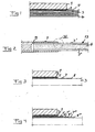
- It is schematically illustrated in
Fig 1 how acomponent 1 of for example aluminium having a high stiffness is adhesively bonded through an adhesive joint 2 to afibre composite laminate 3. This laminate is composed by a plurality ofsuperimposed layers 4 each having substantially parallel fibres embedded in a matrix. A typical thickness of such alayer 4 is 0.1-0.3 mm. The material of these layers may for instance be carbon fibres embedded in an epoxy matrix, glass fibres embedded in a polyester matrix or kevlar fibres embedded in a matrix. Concentrations of shear and tension forces in the adhesive joint will appear at theborder 5 of the component where the border of the latter is located in overlap with the laminate. Such concentrations reduce the possibility to introduce load into the laminate in the same order of magnitude as the load for which the laminate is dimensioned. Furthermore, a substantial difference of the coefficient of thermal expansion of the material of the component with respect to the material of thelaminate 3 results in a risk of introducing stresses destroying the adhesive joint or the laminate layer closest thereto when the temperature is changed substantially. - A method for securing a component having a high stiffness to a fibre composite laminate by adhesive bonding according to the invention is illustrated through
Figs 2 and 3 . Thecomponent 1 is here secured to alaminate 3', 3" forming a cover of reinforcement of asandwich construction 13 on the respective side of anintermediate core material 6 of a comparatively low stiffness and strength. It is illustrated how asheet 7 having, thanks to a much lower thickness than the thickness of thecomponent 1, a substantially lower stiffness than the stiffness of the component is interposed between the component and the laminate so that the sheet extends and has itsborder 8 substantially beyond theborder 5 of the component where the border of the latter is located in overlap with the laminate. The sheet is affixed by adhesively bonding to the laminate as well as to the component for securing them to each other. The distance between theborder 8 of the sheet and that 5 of the component may typically be in the order of 2-8 mm. The sheet may typically have a thickness of 0.5-2 mm. Thesheet 7 has preferably a stiffness in the same order of magnitude as the stiffness of a laminate layer to which it is adhesively bonded, which means that it is avoided to introduce considerably higher loads into the laminate layer than it may withstand. Furthermore, concentrations of shear and tension forces at the end of the adhesive joint at 5 are transferred to thesheet 7 and results in lower shear and tension forces in the region of theborder 8. The sheet is preferably adhesively bonded to the sandwich construction in the same step as this is cured under high temperatures and pressures in a so-called autoclave. The low thickness of thesheet 7 makes it possible to handle it as if it would be a prepreg piece easy to handle. The sheet shall accordingly have a substantially lower stiffness than the stiffness of the component, and have substantially the same coefficient of thermal expansion as the laminate. Steel, titan or invar are preferred materials for the sheet in the case of a laminate of carbon fibre epoxy. Invar appears to be most preferred with respect to the coefficient of thermal expansion being nearly zero, especially when the Ni portion thereof is about 36 percent by weight. Acomponent 1 of aluminium or another metal may be affixed by adhesive bonding through traditional adhesive joints and methods. -
Fig 4 illustrates how a plurality of saidsheets 7', 7", 7"' are superimposed and adhesively bonded to each other and interposed between the component and the laminate as a package according to another preferred embodiment of the method according to the invention. The outer sheets 7', 7'" of said package are adhesively bonded to the component and the laminate, respectively, so that for adjacent sheets saidborder 8', 8" of the sheet closest to the component is located at a shorter distance to saidborder 5 of the component than saidborder 8", 8"' of the other sheet. The concentration of shear and tension forces at the border of the adhesive joint between the component and the sheet is by this reduced at each step so formed for making these forces low in the adhesive joint between thesheet 8"' and thelaminate 3. - It is shown in
Fig 2 how the component is secured to the laminate close to aborder 9 thereof so that is projects beyond the border of the laminate. A preferred way to proceed in such a case is illustrated inFig 5 . It is shown how asheet 7 is adhesively bonded to thelaminate 3 so that aportion 10 thereof will be located in the region near saidborder 9 of the laminate, so that thecomponent 1 is adhesively bonded to a surface of the sheet ending at a distance from said border of the laminate. This means that concentration of shear and tension forces at the adhesivejoint border 11 between the component and the sheet will be distributed over a larger area and result in lower shear and tension forces next to the laminate at theborder 9. The sheet (7) may be adhesively bonded to the laminate (3) so that a portion (10) thereof with a reduced thickness with respect to the rest of the sheet will be located in the region near said border (9) of the laminate, so that the component is adhesively bonded to a surface of the sheet ending at a distance from said border of the laminate. - It is illustrated in
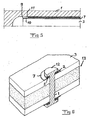
Fig 6 how the method according to the invention may be used for securing a so-calledinsert 12 to asandwich construction 13. This component is introduced through the thickness of the sandwich construction, and a saidsheet 7 having the character of a washer is used when securing the insert to an outer surface of the sandwich construction formed by a said laminate. It is pointed out that this figure is very simplified and used only for illustrating the method according to the invention, and thecomponent 1 may of course in the practice have an arbitrary extension and design on the respective side of the sandwich construction. - The invention is of course not in any way restricted to the preferred embodiments described above, but many possibilities to modifications thereof will be apparent to a person with ordinary skill in the art without departing from the scope of the appended claims.
- The invention is not restricted to the order of adhesively bonding the different pieces to each other described above, but this order may be different, so that the component may be adhesively bonded to said sheet simultaneously as the sheet is adhesively bonded to the laminate.
- The component may be adhesively bonded to a surface portion of the laminate distant from any border of the laminate.
- The lower stiffness of the sheet than of the component is preferably obtained by using a lower thickness for the former, such as less than ½ or ¼ of the thickness of the component. However, it is conceivable to use a material having a substantially lower modulus of elasticity and the same thickness for the sheet or combining these features for obtaining said substantially lower stiffness.
Claims (21)
- A method for securing a component (1) having a high stiffness to a fibre composite laminate (3) by adhesive bonding, characterized in that a sheet (7) having a substantially lower stiffness than the stiffness of the component (1) is interposed between the component (1) and the laminate (3) so that the sheet (7) extends and has its border (8) substantially beyond the border (5) of the component (1) where the border (8) of the latter is located in overlap with the laminate (3), and that the sheet (7) is affixed by adhesively bonding to the laminate (3) as well as the component (1) for securing them to each other.
- A method according to claim 1, characterized in that it is a said sheet (7) having a stiffness in the same order of magnitude as the stiffness of a laminate layer (4) to which it is adhesively bonded that is interposed between the component (1) and the laminate (3).
- A method according to claim 1 or 2, characterized in that the lower stiffness of said sheet (7) in relation to said component (1) is substantially obtained by using a sheet (7) having a substantially lower thickness than the component (1) close to said border (5) thereof, advantageously a thickness being less than ½ and preferably less than ¼ of said thickness of the component (1).
- A method according to any of the preceding claims, characterized in that it is a component (1) made of a metal that is secured to the fibre composite laminate (3).
- A method according to claim 4, characterized in that it is a component (1) made of aluminium that is secured to the fibre composite laminate (3).
- A method according to any of the preceding claims, characterized in that it is a sheet (7) of metal that is interposed between the component (1) and the laminate (3).
- A method according to any of the preceding claims, characterized in that it is a sheet (7) of a material having substantially the same coefficient of thermal expansion as said laminate (3) that is interposed between the component (1) and the laminate (3).
- A method according to any of the preceding claims, characterized in that it is a sheet (7) of steel, titan or invar that is interposed between the component (1) and the laminate (3).
- A method according to any of the preceding claims, characterized in that said component (1) is secured to a laminate (3) having a plurality of layers (4), each layer (4) having substantially parallel carbon fibres embedded in a matrix.
- A method according to claim 9, characterized in that said component (1) is secured to a carbon fibre epoxy laminate (3).
- A method according to any of the preceding claims, characterized in that the component (1) is secured to a glass fibre polyester laminate (3).
- A method according to any of the preceding claims, characterized in that a plurality of said sheets (7', 7", 7"') are superimposed and adhesively bonded to each other and interposed between the component (1) and the laminate (3) as a package, and that the outer sheets (7', 7"') of said package are adhesively bonded to the component (1) and the laminate (3), respectively, so that for adjacent sheets said border (8', 8") of the sheet (7', 7") closest to the component (1) is located at a shorter distance to said border (5) of the component than said border (8", 8"') of the other sheet (7", 7"').
- A method according to any of claims 1-11, characterized in that a sheet (7) having a thickness being stepwisely reduced between said border (5) of the component and said border (8) of the sheet is adhesively bonded to the laminate (3) and the component (1).
- A method according to any of the preceding claims, characterized in that it is a sheet (7) having a thickness of 0.5-2 mm that is interposed between the component (1) and the laminate (3) and so that the distance of said border (8) of the sheet (7) to said border (5) of the component (1) is at least 2 mm, preferably 2-8 mm.
- A method according to any of the preceding claims, characterized in that the sheet (7) is in a step fixed to the laminate (3) by adhesively bonding and the component (1) is in a subsequent separate step fixed to the sheet (7) by adhesive bonding.
- A method according to any of the preceding claims, characterized in that the component (1) is secured to a laminate (3) forming a cover of reinforcement of a sandwich construction (13).
- A method according to claims 15 and 16, characterized in that the sheet (7) is adhesively bonded to the laminate (3) in the same step as the sandwich construction (13) is cured.
- A method according to claim 16 or 17, characterized in that said component is a so-called insert (12) introduced through the thickness of said sandwich construction (13), and that a said sheet (7) having the character of a washer is used when securing the insert to an outer surface of the sandwich construction formed by a said laminate (3).
- A method according to any of claims 1-17, characterized in that said component (1) is secured to the laminate (3) close to a border (9) thereof so that it projects beyond the border (9) of the laminate (3').
- A method according to claim 19, characterized in that a said sheet (7) is adhesively bonded to the laminate (3) so that a portion (10) thereof with a reduced thickness with respect to the rest of the sheet (7) will be located in the region near said border (9) of the laminate, so that the component is adhesively bonded to a surface of the sheet (7) ending at a distance from said border (9) of the laminate.
- Use of the method according to any of the preceding claims, as a part of a process for producing a product to be used in space.
Priority Applications (4)
| Application Number | Priority Date | Filing Date | Title |
|---|---|---|---|
| EP03022314A EP1520895B1 (en) | 2003-10-03 | 2003-10-03 | A method for securing a component |
| AT03022314T ATE456636T1 (en) | 2003-10-03 | 2003-10-03 | METHOD FOR CONNECTING A COMPONENT |
| ES03022314T ES2338541T3 (en) | 2003-10-03 | 2003-10-03 | PROCEDURE TO INSURE A COMPONENT. |
| DE60331146T DE60331146D1 (en) | 2003-10-03 | 2003-10-03 | Method for connecting a component |
Applications Claiming Priority (1)
| Application Number | Priority Date | Filing Date | Title |
|---|---|---|---|
| EP03022314A EP1520895B1 (en) | 2003-10-03 | 2003-10-03 | A method for securing a component |
Publications (2)
| Publication Number | Publication Date |
|---|---|
| EP1520895A1 EP1520895A1 (en) | 2005-04-06 |
| EP1520895B1 true EP1520895B1 (en) | 2010-01-27 |
Family
ID=34306822
Family Applications (1)
| Application Number | Title | Priority Date | Filing Date |
|---|---|---|---|
| EP03022314A Expired - Lifetime EP1520895B1 (en) | 2003-10-03 | 2003-10-03 | A method for securing a component |
Country Status (4)
| Country | Link |
|---|---|
| EP (1) | EP1520895B1 (en) |
| AT (1) | ATE456636T1 (en) |
| DE (1) | DE60331146D1 (en) |
| ES (1) | ES2338541T3 (en) |
Cited By (1)
| Publication number | Priority date | Publication date | Assignee | Title |
|---|---|---|---|---|
| DE102011004775A1 (en) * | 2011-02-25 | 2012-08-30 | Airbus Operations Gmbh | Method of making a connection, connection and aircraft or spacecraft |
Families Citing this family (2)
| Publication number | Priority date | Publication date | Assignee | Title |
|---|---|---|---|---|
| US7393488B2 (en) | 2005-05-25 | 2008-07-01 | The Boeing Company | Methods of joining structures and joints formed thereby |
| DE102013222970B4 (en) | 2013-11-12 | 2023-07-27 | Deutsches Zentrum für Luft- und Raumfahrt e.V. | Method for connecting two components, connecting section of a component and composite component |
Family Cites Families (3)
| Publication number | Priority date | Publication date | Assignee | Title |
|---|---|---|---|---|
| US4556592A (en) * | 1981-09-25 | 1985-12-03 | The Boeing Company | Conductive joint seals for composite aircraft |
| US4966802A (en) * | 1985-05-10 | 1990-10-30 | The Boeing Company | Composites made of fiber reinforced resin elements joined by adhesive |
| SE0004310L (en) * | 2000-11-24 | 2002-01-15 | Saab Ericsson Space Ab | Design and procedure of carrier rocket or satellite |
-
2003
- 2003-10-03 DE DE60331146T patent/DE60331146D1/en not_active Expired - Lifetime
- 2003-10-03 ES ES03022314T patent/ES2338541T3/en not_active Expired - Lifetime
- 2003-10-03 EP EP03022314A patent/EP1520895B1/en not_active Expired - Lifetime
- 2003-10-03 AT AT03022314T patent/ATE456636T1/en not_active IP Right Cessation
Non-Patent Citations (1)
| Title |
|---|
| DANIEL GAY: "MATERIAUX COMPOSITES", 1991, HERMES, PARIS, ISBN: 2-86601-116-3 * |
Cited By (2)
| Publication number | Priority date | Publication date | Assignee | Title |
|---|---|---|---|---|
| DE102011004775A1 (en) * | 2011-02-25 | 2012-08-30 | Airbus Operations Gmbh | Method of making a connection, connection and aircraft or spacecraft |
| DE102011004775B4 (en) * | 2011-02-25 | 2012-10-25 | Airbus Operations Gmbh | Method of making a connection, connection and aircraft or spacecraft |
Also Published As
| Publication number | Publication date |
|---|---|
| ES2338541T3 (en) | 2010-05-10 |
| DE60331146D1 (en) | 2010-03-18 |
| EP1520895A1 (en) | 2005-04-06 |
| ATE456636T1 (en) | 2010-02-15 |
Similar Documents
| Publication | Publication Date | Title |
|---|---|---|
| RU2420407C2 (en) | Thin-layer laminates | |
| JP5429779B2 (en) | Mixed 3D woven / laminated struts for applying composite structures | |
| US5227216A (en) | Fiber/metal laminate | |
| CA2473346C (en) | Lightweight structure particularly for aircraft | |
| US8317134B2 (en) | Stiffened casing for an aircraft or spacecraft with a laminate stringer of high rigidity and corresponding laminate stringer | |
| US8722201B2 (en) | Connections between a monolithic metal component and a continuous-fiber reinforced laminate component, and method for production of the same | |
| CN101300124A (en) | Stringpiece with bulb made of composite material | |
| KR101111993B1 (en) | Force-introduction point in core composites and method for producing said point using reinforcement elements that traverse the thickness of the core composite | |
| US7255916B2 (en) | Metallic layer material, reinforced with basalt fibers, as well as products made thereof | |
| EP1520895B1 (en) | A method for securing a component | |
| JP4855932B2 (en) | Locally reinforced laminate | |
| RU2352464C2 (en) | Light structure and method for its manufacture | |
| EP1114771A1 (en) | Composite material, particularly for sails and the like | |
| JPS602540B2 (en) | composite leaf spring | |
| JPS59133042A (en) | Fiber reinforced composite laminated material and its manufacture | |
| JP2004155157A (en) | Composite material joint | |
| JPH01263030A (en) | Fastener joint for composite material | |
| JP4115702B2 (en) | Tension rod for use as a bridge cord | |
| JPH01110943A (en) | Frp structure and its manufacture | |
| MOLODTSOV | Micro-mechanical analysis of prestressed fiber reinforced composite laminates | |
| JPH04366134A (en) | Fiber-reinforced plastic having high strength | |
| JP2003042233A (en) | Joint structure of frp belt for structure |
Legal Events
| Date | Code | Title | Description |
|---|---|---|---|
| PUAI | Public reference made under article 153(3) epc to a published international application that has entered the european phase |
Free format text: ORIGINAL CODE: 0009012 |
|
| AK | Designated contracting states |
Kind code of ref document: A1 Designated state(s): AT BE BG CH CY CZ DE DK EE ES FI FR GB GR HU IE IT LI LU MC NL PT RO SE SI SK TR |
|
| AX | Request for extension of the european patent |
Extension state: AL LT LV MK |
|
| 17P | Request for examination filed |
Effective date: 20050825 |
|
| AKX | Designation fees paid |
Designated state(s): AT BE BG CH CY CZ DE DK EE ES FI FR GB GR HU IE IT LI LU MC NL PT RO SE SI SK TR |
|
| 17Q | First examination report despatched |
Effective date: 20070418 |
|
| RAP1 | Party data changed (applicant data changed or rights of an application transferred) |
Owner name: SAAB AB |
|
| RAP1 | Party data changed (applicant data changed or rights of an application transferred) |
Owner name: RUAG AEROSPACE SWEDEN AB |
|
| GRAP | Despatch of communication of intention to grant a patent |
Free format text: ORIGINAL CODE: EPIDOSNIGR1 |
|
| GRAS | Grant fee paid |
Free format text: ORIGINAL CODE: EPIDOSNIGR3 |
|
| GRAA | (expected) grant |
Free format text: ORIGINAL CODE: 0009210 |
|
| AK | Designated contracting states |
Kind code of ref document: B1 Designated state(s): AT BE BG CH CY CZ DE DK EE ES FI FR GB GR HU IE IT LI LU MC NL PT RO SE SI SK TR |
|
| REG | Reference to a national code |
Ref country code: GB Ref legal event code: FG4D |
|
| REG | Reference to a national code |
Ref country code: CH Ref legal event code: EP |
|
| REG | Reference to a national code |
Ref country code: IE Ref legal event code: FG4D |
|
| REF | Corresponds to: |
Ref document number: 60331146 Country of ref document: DE Date of ref document: 20100318 Kind code of ref document: P |
|
| REG | Reference to a national code |
Ref country code: ES Ref legal event code: FG2A Ref document number: 2338541 Country of ref document: ES Kind code of ref document: T3 |
|
| REG | Reference to a national code |
Ref country code: NL Ref legal event code: VDEP Effective date: 20100127 |
|
| PG25 | Lapsed in a contracting state [announced via postgrant information from national office to epo] |
Ref country code: AT Free format text: LAPSE BECAUSE OF FAILURE TO SUBMIT A TRANSLATION OF THE DESCRIPTION OR TO PAY THE FEE WITHIN THE PRESCRIBED TIME-LIMIT Effective date: 20100127 |
|
| PG25 | Lapsed in a contracting state [announced via postgrant information from national office to epo] |
Ref country code: PT Free format text: LAPSE BECAUSE OF FAILURE TO SUBMIT A TRANSLATION OF THE DESCRIPTION OR TO PAY THE FEE WITHIN THE PRESCRIBED TIME-LIMIT Effective date: 20100527 Ref country code: NL Free format text: LAPSE BECAUSE OF FAILURE TO SUBMIT A TRANSLATION OF THE DESCRIPTION OR TO PAY THE FEE WITHIN THE PRESCRIBED TIME-LIMIT Effective date: 20100127 |
|
| PG25 | Lapsed in a contracting state [announced via postgrant information from national office to epo] |
Ref country code: FI Free format text: LAPSE BECAUSE OF FAILURE TO SUBMIT A TRANSLATION OF THE DESCRIPTION OR TO PAY THE FEE WITHIN THE PRESCRIBED TIME-LIMIT Effective date: 20100127 Ref country code: SI Free format text: LAPSE BECAUSE OF FAILURE TO SUBMIT A TRANSLATION OF THE DESCRIPTION OR TO PAY THE FEE WITHIN THE PRESCRIBED TIME-LIMIT Effective date: 20100127 |
|
| PG25 | Lapsed in a contracting state [announced via postgrant information from national office to epo] |
Ref country code: GR Free format text: LAPSE BECAUSE OF FAILURE TO SUBMIT A TRANSLATION OF THE DESCRIPTION OR TO PAY THE FEE WITHIN THE PRESCRIBED TIME-LIMIT Effective date: 20100428 Ref country code: SE Free format text: LAPSE BECAUSE OF FAILURE TO SUBMIT A TRANSLATION OF THE DESCRIPTION OR TO PAY THE FEE WITHIN THE PRESCRIBED TIME-LIMIT Effective date: 20100127 Ref country code: RO Free format text: LAPSE BECAUSE OF FAILURE TO SUBMIT A TRANSLATION OF THE DESCRIPTION OR TO PAY THE FEE WITHIN THE PRESCRIBED TIME-LIMIT Effective date: 20100127 Ref country code: EE Free format text: LAPSE BECAUSE OF FAILURE TO SUBMIT A TRANSLATION OF THE DESCRIPTION OR TO PAY THE FEE WITHIN THE PRESCRIBED TIME-LIMIT Effective date: 20100127 Ref country code: CY Free format text: LAPSE BECAUSE OF FAILURE TO SUBMIT A TRANSLATION OF THE DESCRIPTION OR TO PAY THE FEE WITHIN THE PRESCRIBED TIME-LIMIT Effective date: 20100127 Ref country code: BE Free format text: LAPSE BECAUSE OF FAILURE TO SUBMIT A TRANSLATION OF THE DESCRIPTION OR TO PAY THE FEE WITHIN THE PRESCRIBED TIME-LIMIT Effective date: 20100127 |
|
| PG25 | Lapsed in a contracting state [announced via postgrant information from national office to epo] |
Ref country code: CZ Free format text: LAPSE BECAUSE OF FAILURE TO SUBMIT A TRANSLATION OF THE DESCRIPTION OR TO PAY THE FEE WITHIN THE PRESCRIBED TIME-LIMIT Effective date: 20100127 Ref country code: BG Free format text: LAPSE BECAUSE OF FAILURE TO SUBMIT A TRANSLATION OF THE DESCRIPTION OR TO PAY THE FEE WITHIN THE PRESCRIBED TIME-LIMIT Effective date: 20100427 Ref country code: SK Free format text: LAPSE BECAUSE OF FAILURE TO SUBMIT A TRANSLATION OF THE DESCRIPTION OR TO PAY THE FEE WITHIN THE PRESCRIBED TIME-LIMIT Effective date: 20100127 |
|
| PLBE | No opposition filed within time limit |
Free format text: ORIGINAL CODE: 0009261 |
|
| STAA | Information on the status of an ep patent application or granted ep patent |
Free format text: STATUS: NO OPPOSITION FILED WITHIN TIME LIMIT |
|
| 26N | No opposition filed |
Effective date: 20101028 |
|
| PG25 | Lapsed in a contracting state [announced via postgrant information from national office to epo] |
Ref country code: DK Free format text: LAPSE BECAUSE OF FAILURE TO SUBMIT A TRANSLATION OF THE DESCRIPTION OR TO PAY THE FEE WITHIN THE PRESCRIBED TIME-LIMIT Effective date: 20100127 |
|
| PG25 | Lapsed in a contracting state [announced via postgrant information from national office to epo] |
Ref country code: MC Free format text: LAPSE BECAUSE OF NON-PAYMENT OF DUE FEES Effective date: 20101031 |
|
| REG | Reference to a national code |
Ref country code: CH Ref legal event code: PL |
|
| PG25 | Lapsed in a contracting state [announced via postgrant information from national office to epo] |
Ref country code: LI Free format text: LAPSE BECAUSE OF NON-PAYMENT OF DUE FEES Effective date: 20101031 Ref country code: CH Free format text: LAPSE BECAUSE OF NON-PAYMENT OF DUE FEES Effective date: 20101031 |
|
| PG25 | Lapsed in a contracting state [announced via postgrant information from national office to epo] |
Ref country code: IE Free format text: LAPSE BECAUSE OF NON-PAYMENT OF DUE FEES Effective date: 20101003 |
|
| PG25 | Lapsed in a contracting state [announced via postgrant information from national office to epo] |
Ref country code: HU Free format text: LAPSE BECAUSE OF FAILURE TO SUBMIT A TRANSLATION OF THE DESCRIPTION OR TO PAY THE FEE WITHIN THE PRESCRIBED TIME-LIMIT Effective date: 20100728 Ref country code: LU Free format text: LAPSE BECAUSE OF NON-PAYMENT OF DUE FEES Effective date: 20101003 |
|
| PG25 | Lapsed in a contracting state [announced via postgrant information from national office to epo] |
Ref country code: TR Free format text: LAPSE BECAUSE OF FAILURE TO SUBMIT A TRANSLATION OF THE DESCRIPTION OR TO PAY THE FEE WITHIN THE PRESCRIBED TIME-LIMIT Effective date: 20100127 |
|
| REG | Reference to a national code |
Ref country code: FR Ref legal event code: PLFP Year of fee payment: 14 |
|
| REG | Reference to a national code |
Ref country code: FR Ref legal event code: PLFP Year of fee payment: 15 |
|
| REG | Reference to a national code |
Ref country code: FR Ref legal event code: PLFP Year of fee payment: 16 |
|
| PG25 | Lapsed in a contracting state [announced via postgrant information from national office to epo] |
Ref country code: IT Free format text: LAPSE BECAUSE OF NON-PAYMENT OF DUE FEES Effective date: 20191003 |
|
| PGFP | Annual fee paid to national office [announced via postgrant information from national office to epo] |
Ref country code: GB Payment date: 20200916 Year of fee payment: 18 Ref country code: FR Payment date: 20200911 Year of fee payment: 18 |
|
| PGFP | Annual fee paid to national office [announced via postgrant information from national office to epo] |
Ref country code: DE Payment date: 20200922 Year of fee payment: 18 Ref country code: ES Payment date: 20201102 Year of fee payment: 18 |
|
| REG | Reference to a national code |
Ref country code: DE Ref legal event code: R119 Ref document number: 60331146 Country of ref document: DE |
|
| GBPC | Gb: european patent ceased through non-payment of renewal fee |
Effective date: 20211003 |
|
| PG25 | Lapsed in a contracting state [announced via postgrant information from national office to epo] |
Ref country code: GB Free format text: LAPSE BECAUSE OF NON-PAYMENT OF DUE FEES Effective date: 20211003 Ref country code: DE Free format text: LAPSE BECAUSE OF NON-PAYMENT OF DUE FEES Effective date: 20220503 |
|
| PG25 | Lapsed in a contracting state [announced via postgrant information from national office to epo] |
Ref country code: FR Free format text: LAPSE BECAUSE OF NON-PAYMENT OF DUE FEES Effective date: 20211031 |
|
| REG | Reference to a national code |
Ref country code: ES Ref legal event code: FD2A Effective date: 20221125 |
|
| PG25 | Lapsed in a contracting state [announced via postgrant information from national office to epo] |
Ref country code: ES Free format text: LAPSE BECAUSE OF NON-PAYMENT OF DUE FEES Effective date: 20211004 |