EP1520842A1 - Method of manufacturing window having at least one of radio wave stealth property and electromagnetic wave shield property, and window material having at least one of radio wave stealth property and electromagnetic wave shield property - Google Patents
Method of manufacturing window having at least one of radio wave stealth property and electromagnetic wave shield property, and window material having at least one of radio wave stealth property and electromagnetic wave shield property Download PDFInfo
- Publication number
- EP1520842A1 EP1520842A1 EP04023041A EP04023041A EP1520842A1 EP 1520842 A1 EP1520842 A1 EP 1520842A1 EP 04023041 A EP04023041 A EP 04023041A EP 04023041 A EP04023041 A EP 04023041A EP 1520842 A1 EP1520842 A1 EP 1520842A1
- Authority
- EP
- European Patent Office
- Prior art keywords
- film
- mesh
- thin
- property
- window
- Prior art date
- Legal status (The legal status is an assumption and is not a legal conclusion. Google has not performed a legal analysis and makes no representation as to the accuracy of the status listed.)
- Granted
Links
- 238000004519 manufacturing process Methods 0.000 title claims abstract description 44
- 239000000463 material Substances 0.000 title claims description 16
- 239000010409 thin film Substances 0.000 claims abstract description 118
- 239000004020 conductor Substances 0.000 claims abstract description 25
- 238000005452 bending Methods 0.000 claims description 26
- 230000005855 radiation Effects 0.000 abstract description 7
- 230000009545 invasion Effects 0.000 abstract description 3
- 239000010408 film Substances 0.000 description 54
- 238000000034 method Methods 0.000 description 31
- 229920005989 resin Polymers 0.000 description 14
- 239000011347 resin Substances 0.000 description 14
- 230000000694 effects Effects 0.000 description 7
- 239000000853 adhesive Substances 0.000 description 6
- 230000001070 adhesive effect Effects 0.000 description 6
- 239000010410 layer Substances 0.000 description 5
- 230000037303 wrinkles Effects 0.000 description 5
- 238000000576 coating method Methods 0.000 description 4
- 229910052751 metal Inorganic materials 0.000 description 4
- 239000002184 metal Substances 0.000 description 4
- 239000004925 Acrylic resin Substances 0.000 description 3
- 229920000178 Acrylic resin Polymers 0.000 description 3
- RYGMFSIKBFXOCR-UHFFFAOYSA-N Copper Chemical compound [Cu] RYGMFSIKBFXOCR-UHFFFAOYSA-N 0.000 description 3
- DQXBYHZEEUGOBF-UHFFFAOYSA-N but-3-enoic acid;ethene Chemical compound C=C.OC(=O)CC=C DQXBYHZEEUGOBF-UHFFFAOYSA-N 0.000 description 3
- 229910052802 copper Inorganic materials 0.000 description 3
- 239000010949 copper Substances 0.000 description 3
- 239000005038 ethylene vinyl acetate Substances 0.000 description 3
- 238000001259 photo etching Methods 0.000 description 3
- 238000007747 plating Methods 0.000 description 3
- 229920001200 poly(ethylene-vinyl acetate) Polymers 0.000 description 3
- PXHVJJICTQNCMI-UHFFFAOYSA-N Nickel Chemical compound [Ni] PXHVJJICTQNCMI-UHFFFAOYSA-N 0.000 description 2
- 239000000919 ceramic Substances 0.000 description 2
- 238000005229 chemical vapour deposition Methods 0.000 description 2
- 239000011248 coating agent Substances 0.000 description 2
- 238000010276 construction Methods 0.000 description 2
- 238000005336 cracking Methods 0.000 description 2
- PCHJSUWPFVWCPO-UHFFFAOYSA-N gold Chemical compound [Au] PCHJSUWPFVWCPO-UHFFFAOYSA-N 0.000 description 2
- 229910052737 gold Inorganic materials 0.000 description 2
- 239000010931 gold Substances 0.000 description 2
- -1 polyethylene terephthalate Polymers 0.000 description 2
- 229920000139 polyethylene terephthalate Polymers 0.000 description 2
- 239000005020 polyethylene terephthalate Substances 0.000 description 2
- 238000007740 vapor deposition Methods 0.000 description 2
- BLRPTPMANUNPDV-UHFFFAOYSA-N Silane Chemical compound [SiH4] BLRPTPMANUNPDV-UHFFFAOYSA-N 0.000 description 1
- 239000006087 Silane Coupling Agent Substances 0.000 description 1
- BQCADISMDOOEFD-UHFFFAOYSA-N Silver Chemical compound [Ag] BQCADISMDOOEFD-UHFFFAOYSA-N 0.000 description 1
- ATJFFYVFTNAWJD-UHFFFAOYSA-N Tin Chemical compound [Sn] ATJFFYVFTNAWJD-UHFFFAOYSA-N 0.000 description 1
- RTAQQCXQSZGOHL-UHFFFAOYSA-N Titanium Chemical compound [Ti] RTAQQCXQSZGOHL-UHFFFAOYSA-N 0.000 description 1
- 229910052782 aluminium Inorganic materials 0.000 description 1
- XAGFODPZIPBFFR-UHFFFAOYSA-N aluminium Chemical compound [Al] XAGFODPZIPBFFR-UHFFFAOYSA-N 0.000 description 1
- 230000008602 contraction Effects 0.000 description 1
- KPUWHANPEXNPJT-UHFFFAOYSA-N disiloxane Chemical class [SiH3]O[SiH3] KPUWHANPEXNPJT-UHFFFAOYSA-N 0.000 description 1
- 230000007613 environmental effect Effects 0.000 description 1
- 239000003822 epoxy resin Substances 0.000 description 1
- 238000005530 etching Methods 0.000 description 1
- 238000004299 exfoliation Methods 0.000 description 1
- 239000011521 glass Substances 0.000 description 1
- 238000010438 heat treatment Methods 0.000 description 1
- AMGQUBHHOARCQH-UHFFFAOYSA-N indium;oxotin Chemical compound [In].[Sn]=O AMGQUBHHOARCQH-UHFFFAOYSA-N 0.000 description 1
- 239000007769 metal material Substances 0.000 description 1
- 229910052759 nickel Inorganic materials 0.000 description 1
- 239000003973 paint Substances 0.000 description 1
- 229920000647 polyepoxide Polymers 0.000 description 1
- 229920001709 polysilazane Polymers 0.000 description 1
- 229920002635 polyurethane Polymers 0.000 description 1
- 239000004814 polyurethane Substances 0.000 description 1
- 239000011241 protective layer Substances 0.000 description 1
- 230000035945 sensitivity Effects 0.000 description 1
- 229910000077 silane Inorganic materials 0.000 description 1
- 229910052709 silver Inorganic materials 0.000 description 1
- 239000004332 silver Substances 0.000 description 1
- 239000000126 substance Substances 0.000 description 1
- 229910052718 tin Inorganic materials 0.000 description 1
- 239000011135 tin Substances 0.000 description 1
- 229910052719 titanium Inorganic materials 0.000 description 1
- 239000010936 titanium Substances 0.000 description 1
- 238000007738 vacuum evaporation Methods 0.000 description 1
- 238000007666 vacuum forming Methods 0.000 description 1
Images


Classifications
-
- H—ELECTRICITY
- H05—ELECTRIC TECHNIQUES NOT OTHERWISE PROVIDED FOR
- H05K—PRINTED CIRCUITS; CASINGS OR CONSTRUCTIONAL DETAILS OF ELECTRIC APPARATUS; MANUFACTURE OF ASSEMBLAGES OF ELECTRICAL COMPONENTS
- H05K9/00—Screening of apparatus or components against electric or magnetic fields
- H05K9/0073—Shielding materials
-
- B—PERFORMING OPERATIONS; TRANSPORTING
- B64—AIRCRAFT; AVIATION; COSMONAUTICS
- B64C—AEROPLANES; HELICOPTERS
- B64C1/00—Fuselages; Constructional features common to fuselages, wings, stabilising surfaces or the like
- B64C1/14—Windows; Doors; Hatch covers or access panels; Surrounding frame structures; Canopies; Windscreens accessories therefor, e.g. pressure sensors, water deflectors, hinges, seals, handles, latches, windscreen wipers
- B64C1/1476—Canopies; Windscreens or similar transparent elements
- B64C1/1484—Windows
-
- B—PERFORMING OPERATIONS; TRANSPORTING
- B64—AIRCRAFT; AVIATION; COSMONAUTICS
- B64D—EQUIPMENT FOR FITTING IN OR TO AIRCRAFT; FLIGHT SUITS; PARACHUTES; ARRANGEMENTS OR MOUNTING OF POWER PLANTS OR PROPULSION TRANSMISSIONS IN AIRCRAFT
- B64D7/00—Arrangements of military equipment, e.g. armaments, armament accessories, or military shielding, in aircraft; Adaptations of armament mountings for aircraft
-
- C—CHEMISTRY; METALLURGY
- C03—GLASS; MINERAL OR SLAG WOOL
- C03C—CHEMICAL COMPOSITION OF GLASSES, GLAZES OR VITREOUS ENAMELS; SURFACE TREATMENT OF GLASS; SURFACE TREATMENT OF FIBRES OR FILAMENTS MADE FROM GLASS, MINERALS OR SLAGS; JOINING GLASS TO GLASS OR OTHER MATERIALS
- C03C17/00—Surface treatment of glass, not in the form of fibres or filaments, by coating
- C03C17/001—General methods for coating; Devices therefor
-
- F—MECHANICAL ENGINEERING; LIGHTING; HEATING; WEAPONS; BLASTING
- F41—WEAPONS
- F41H—ARMOUR; ARMOURED TURRETS; ARMOURED OR ARMED VEHICLES; MEANS OF ATTACK OR DEFENCE, e.g. CAMOUFLAGE, IN GENERAL
- F41H3/00—Camouflage, i.e. means or methods for concealment or disguise
-
- F—MECHANICAL ENGINEERING; LIGHTING; HEATING; WEAPONS; BLASTING
- F42—AMMUNITION; BLASTING
- F42B—EXPLOSIVE CHARGES, e.g. FOR BLASTING, FIREWORKS, AMMUNITION
- F42B7/00—Shotgun ammunition
Definitions
- the present invention relates to a method of manufacturing a window having at least one of a radio wave stealth property and an electromagnetic wave shield property that is applicable to aircraft or the like, in particular to stealth aircraft, and to a window material having at least one of a radio wave stealth property and an electromagnetic wave shield property.
- a window member composed of a transparent resin or inorganic glass with a transparent conducting film such as gold or ITO (indium tin oxide) coated thereon, as an electromagnetic wave shield window used for aircraft, in particular for stealth aircraft, is known.
- Applying such transparent conducting film enables, while maintaining transparency to visible radiation, both a radio wave stealth property which scatters radio waves in various directions so as not to be detected by radar, and an electromagnetic wave shield property which prevents harmful electromagnetic waves, except for visible radiation, from invasion into an aircraft.
- window members for aircraft especially windshields and canopies are bent at a large curvature and have a multiple curved surface shape, having a plurality of radius of curvature. Therefore there is a problem in that it is difficult to coat a transparent conducting film on a window member in a uniform thickness.
- a window having at least one of a radio wave stealth property and a electromagnetic wave shield property comprising a window member coated with a transparent conducting film, is exposed to a wide range variation in outside pressure and temperature during flight and the window member deforms.
- the transparent conducting film especially ceramic transparent conducting film such as ITO does not deform sufficiently to follow the deformation of the window material. Therefore the transparent conducting film might crack even with relatively little deformation, which can occur during an actual flight.
- especially ceramic transparent conducting film such as ITO is coated on the inner side of the windows, which deform relatively less.
- a front filter applied to a plasma display panel which is in a totally different field of art compared to aircraft windows, is known as a device to shield harmful electromagnetic waves and let only visible radiation go through.
- a front filter of a construction where a resin film of for example PET (polyethylene terephthalate) formed with a conductive mesh thereon, is adhered integrally so as to cover the whole front side of a plasma display panel.
- PET polyethylene terephthalate
- Such a front filter is essentially flat because it is supposed to be applied to a plasma display panel. Therefore, it is difficult to apply such a front filter to a window having a multiple curved surface shape such as for an aircraft canopy.
- the present invention takes into account the above problems with an object of; providing a method of manufacturing a window having at least one of a radio wave stealth property and an electromagnetic wave shield property, that enables manufacture, at lower cost, a window having a radio wave stealth property that scatters radio waves in various directions so as not to be detected by radar, while transparency to visible light is improved, as well as a window having an electromagnetic wave shield property that effectively prevents harmful electromagnetic waves, except for visible radiation, from invasion into an aircraft, and providing a window material having at least one of a radio wave stealth property and an electromagnetic wave shield property.
- the present invention provides the following means.
- a first aspect of the present invention is a method of manufacturing a window having at least one of a radio wave stealth property and an electromagnetic wave shield property comprising: a step for forming a thin-film composed of a conductive material on the surface of a transparent window member having a curved surface, and a step for forming the thin-film into a mesh shape.
- the thin-film composed of the conductive material by using for example, a coating method such as plating or metallic vapor deposition or the like.
- a coating method such as plating or metallic vapor deposition or the like.
- the fine mesh is formed by a photo-etching method in a subsequent process, there is not such sensitivity to non-uniformity of the thin-film such as uneven thickness after the coating, as in the case of coating with a transparent conductive film.
- the thin-film, composed of a conductive material and adhered firmly on the surface of the window member is formed into a mesh shape by, for example, a photo-etching method or the like.
- a second aspect of the present invention is a method of manufacturing a window having at least one of a radio wave stealth property and an electromagnetic wave shield property comprising: a step for forming a mesh-shaped-thin-film composed of a conductive material on the surface of a flat-shaped transparent window member, and a step for integrally bending the window member and the-thin film, and forming into a curved shape.
- a third aspect of the present invention is a method of manufacturing a window having at least one of a radio wave stealth property and an electromagnetic wave shield property comprising: a step for forming a mesh-shaped-thin-film composed of a conductive material on the surface of a transparent window member having a single curved surface shape, and a step for integrally bending the window member and the thin-film, and forming into multiple curved surface shape.
- the mesh-shaped-thin-film composed of a conductive material is formed beforehand on the surface of a transparent window member that is a flat-shaped or has a single curved surface shape. Therefore, according to these aspects, because the window member has a flat or single curved surface shape, by positioning a resin film or a sheet, on which the mesh-shaped-thin-film is formed, along the surface of the window member, the resin film or sheet can be adhered to the surface without a wrinkle. In addition, even if formed by the thin-film method, the thin film can be relatively easily formed into a uniform thickness.
- the thin-film is formed into a mesh shape, the thin-film deforms when being bent by allowing each mesh line to lengthen individually, making the mesh gaps wider. As a result, the thin-film, follows the expansion of the surface of the window member when being bent, and deforms to maintain firm contact with the window member. Therefore, it is possible to manufacture windows having at least one of a radio wave stealth property and an electromagnetic wave shield property, comprising a window member and mesh-shaped-thin-film on the surface thereof, which is integrally and firmly contacted with the window member even after bending.
- a radio wave stealth property and an electromagnetic wave shield property comprising a window member and mesh-shaped-thin-film on the surface thereof, which is integrally and firmly contacted with the window member even after bending.
- the thin film positioned in an area where a change amount in curvature is higher in a subsequent bending step is formed with a finer mesh.
- the thin-film which is formed on the surface of the window member after being bent into a uniform mesh shape by adjusting the density of the mesh of the thin-film formed on the surface of the window member before being bent, to conform to the variation amount of the curvature of the window member to be bent.
- the mesh lines of the area expands to a mesh size of a density equivalent to those of other areas, after the window-member is bent.
- a mesh-shaped-thin-film having a uniform mesh size is formed.
- the thin film positioned in an area with a large change amount in curvature in a subsequent bending step may be formed with a thicker mesh line.
- the present invention provides a window material having at least one of a radio wave stealth property and an electromagnetic wave shield property comprising a thin-film, which is formed on the surface of a transparent window member having a flat or single curved surface shape, composed of a conductive material that has a finer mesh in an area where a change amount in curvature is higher when being bent.
- the present invention provides a window material having at least one of a radio wave stealth property and an electromagnetic wave shield property comprising a thin-film, which is formed on the surface of a transparent window member having a flat or single curved surface shape, composed of a conductive material that has a thicker mesh line in an area where a change amount in curvature is higher when being bent.
- window materials in the state before being bent, by providing the thin-film composed of a conductive material of a mesh shape of finer mesh size or a thicker mesh line, at a region where the change amount in curvature is higher when being bent, it becomes possible to easily construct windows having at least one of a radio wave stealth property and an electromagnetic wave shield property comprising a thin film composed of a conductive material of a mesh-shape formed uniformly on the whole window, by simply bending the window.
- the present invention there is the effect that it is possible to manufacture an electromagnetic wave shield window that has a bright view, advanced radio wave stealth property, and superior shielding properties against harmful electromagnetic waves.
- the mesh-shaped-thin-film can deform easily following the deformation of the window member.
- Embodiments of a method of manufacturing a window having at least one of a radio wave stealth property and an electromagnetic wave shield property hereunder “electromagnetic wave shield window” according to the present invention will be described hereunder with reference to the drawings.
- a method of manufacturing an electromagnetic wave shield window of a first embodiment of the present invention is a method of manufacturing an electromagnetic wave shield window having a plurality of curved areas such as an aircraft canopy, comprising as shown in FIG. 1; a window member forming step S1 in which a transparent window member having a plurality of curved areas is formed, a thin-film forming step S2 in which a thin-film composed of a conductive material is formed on the surface of the formed window member having a plurality of curved areas, and a mesh forming step S3 in which the formed thin-film is formed into a mesh shape.
- the window member forming step S1 is a step for heating a flat window material made for example from a stretch acrylic resin for aircraft, and press forming between metal dies.
- the thin-film forming step S2 is a step for forming by a plating process a thin-film 2 as shown in FIG. 2B composed of a conductive material such as metal, for example, gold, silver, copper, aluminum, nickel, titanium, or tin, on the surface of a window member 1, which is formed in a multiple curved surface shape as shown in FIG. 2A.
- the thickness of the thin-film 2 is preferably, for example, 1 to 30 ⁇ m, particularly 1 to 20 ⁇ m, and more preferably about 10 ⁇ m.
- the thin-film 2 which is formed on the whole surface of the window member 1, is formed into a mesh-shape-thin-film 3 as shown in FIG. 2C. More specifically, a resist film is formed on the surface of the thin-film 2. Then, a mask pattern on the resist film is exposed, after which this is developed to thereby form a mesh shape mask on the surface of the thin-film 2. By etching the thin-film 2 in this state with chemicals, the thin-film 2 is formed into the mesh-shaped-thin-film 3. Afterward, by removing the resist film, an electromagnetic wave shield window 4, which has the mesh-shape-thin-film 3 formed on the surface of the window member 1 is manufactured.
- the formed mesh-shape-thin-film 3 is preferably about 10 ⁇ m in thickness, respective lines constituting the mesh are about 10 ⁇ m wide, and a gap between the respective lines is about 200 ⁇ m wide. By constructing in this way, about 90% transparency can be achieved. In addition, by constructing the thin-film 3 from a highly conductive material such as copper, it is possible to keep the electrical resistivity to less than a few ohms per square, thus realizing a high electromagnetic wave shield property or a radio wave stealth property.
- the thin-film 2 composed of a conductive material is formed on the surface of the window member 1, which is beforehand formed into a shape having a multi-curved surfaces, after which the formed thin-film 2 is re-formed into the mesh-shaped-thin-film 3. Therefore, it is possible to form the uniform mesh-shaped-thin-film 3 on the whole surface of the window member 1, which has a complicated curved surface shape. Consequently, it is possible to avoid non-uniformity in shielding electromagnetic waves, and partial loss of view, which could be caused if the thin-film 3 were not formed uniformly.
- an electromagnetic wave shield window 4 which can shield electromagnetic waves coming from outside the aircraft while maintaining a good view from inside the aircraft.
- the uniformly formed mesh-shaped-thin-film 3 can scatter electromagnetic waves uniformly making it possible to manufacture a window 4 which has improved radio stealth properties against outside radar.
- the thin-film 3 which covers the surface of the window member 1 is formed into a mesh shape having a plurality of meshes. Therefore, by using metal as the material constituting the thin-film 3, the thin-film 3 can easily deform following the deformation of the window member, even when changes occur in the external environment outside of an aircraft, such as temperature or pressure changes. As a result, an electromagnetic wave shield window 4 having a radio wave stealth property and an electromagnetic wave shield property manufactured by the manufacturing method of the present embodiment, is maintained in a good condition without the occurrence of mesh cracking or exfoliation due to changes in the external environment.
- the mesh-shaped-thin-film 3 can be applied to the outer side of the window member 1 where environmental variations are greater so that deformation of the material is large. Hence, a step difference between the outer surface of the aircraft and the thin-film 3 is prevented, and radio stealth properties can be further improved.
- a method of plating the surface of the window member 1 with a metallic material is shown as an example of the thin-film forming step S1.
- the method is not limited to this, and any method such as vacuum evaporation of a conductive material such as with CVD (chemical vapor deposition) or PVD (plasma vapor deposition), or applying a conductive paint or paste, may be adopted.
- the electromagnetic wave shield window 4 comprising the window member 1 and the mesh-shaped-thin-film 3 is explained above.
- an optional protection layer 5 for protecting the thin-film 3 may also be formed.
- the protection layer 5 polysilazane, polyurethane, polysilicone, or siloxane resins can be used.
- the protection layer 5 may be formed to cover the mesh-shaped-thin-film 3 by any method such as a film application method or a coating method, after forming the mesh-shaped-thin-film 3.
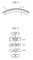
- the method of making an electromagnetic wave shield window comprises as shown in FIG. 4: a thin-film forming step S11 for contact forming on the surface of a flatly-arranged transparent window member, a transparent resin film or sheet formed with a thin-film composed of a conductive material; a mesh forming step S12 for forming the formed thin-film into a mesh shape; and a bending step S13 for integrally bending the window member and the mesh-shaped-thin-film.
- a thin-film composed of a conductive material is formed in the same way as in the first embodiment, on one face of the surface of the flatly-arranged transparent resin film 10.
- the thin-film formed on the film 10 is formed into mesh-shaped-thin-film 11 in the same way as in the first embodiment.
- a mesh film 12 which has the mesh-shaped-thin-film 11 composed of a conductive material adhered firmly on the transparent resin film 10, is manufactured.
- a transparent resin sheet can be used.
- the mesh-shaped-thin-film 11 is provided on the surface of the window member 13.
- the window member 13 comprises, for example, an elastic transparent flat-shape stretch acrylic resin.
- the mesh film 12 comprises copper for example, and is manufactured such that respective lines of the mesh are about 10 ⁇ m in width, about 10 ⁇ m in thickness, and a gap between the lines is about 200 ⁇ m.
- a film-shaped transparent adhesive such as an EVA (ethylene vinyl acetate) with a silane coupler added, or the like may be used.
- the window member 13 and the mesh film 12 which are adhered integrally by the adhesive to constitute the window material are bent at the same time and integrally.
- a bending method for example, press-forming can be adopted.
- an electromagnetic wave shield window 14 having at least one of a radio wave stealth property and an electromagnetic wave shield property is manufactured.
- the mesh film 12 comprising the transparent resin film 10 and the mesh-shaped-thin-film 11 formed thereon, is adhered to the flat-shaped window member 13 before the window member 13 is bent. Therefore, when being adhered, the mesh film 12 can be easily adhered firmly to the whole area of the window member 13. Then afterwards, the mesh film 12 and the window member 13 integrally bent in an integrally adhered condition. Hence it is possible to avoid the occurrence of wrinkles which that are produced when adhering a transparent conductive film to a curved surface of a window member.
- the mesh-shaped-thin-film 11 and the transparent resin film 10 deform to conform to the expansion and contraction of the surface produced when the window member 13 is bent.
- the respective metallic lines of the mesh expand and contract, and the film 10 deforms elastically, so that this deforms while maintaining close contact with the surface of the window member 13.
- an electromagnetic wave shield window 14 having at least one of a radio wave stealth property and an electromagnetic wave shield property, and which comprises a mesh-shaped-thin-film 11 formed uniformly on the curved surface of the window member 13 without wrinkles even after being bent, can be manufactured.
- the electromagnetic wave shield window 14 manufactured in the above manner by the manufacturing method of the present embodiment can also shield electromagnetic waves coming from outside an aircraft while avoiding non-uniformity of shielding of electromagnetic waves and partial loss of view, which could be caused if the mesh-shaped-thin-film 11 was not formed uniformly, and while maintaining a good view from inside the aircraft, similarly to the electromagnetic wave shield window 4 manufactured by the method of the first embodiment.
- the uniformly-formed mesh-shaped-thin-film 11 makes it possible to scatter electromagnetic waves uniformly, with the effect that the radio stealth properties against outside radar can be improved.
- even when the window member deforms due to changes in the external environment it is possible to absorb stresses and maintain a good condition by using the metallic mesh-shaped-thin-film 11.
- the mesh film 12 is adhered to the flat-shaped window member 13.
- the mesh film 12 may be adhered to the window member 1 having a single curved surface shape. With a single curved surface shape, it is possible to adhere the mesh film 12 to the window member 1 firmly without wrinkles by simply bending the mesh film 12. Therefore there is a similar effect to the above embodiment.
- a film shaped adhesive comprising an EVA resin with a silane coupling agent is given as an example.
- an optional adhesive such as epoxy resin or acrylic resin may be employed.
- FIGS. 6A to 6D instead of the method of adhering the mesh film 12 to the window member 13, a method shown in FIGS. 6A to 6D may be employed.
- a method may be employed where, on the window member 13 shown in FIG. 6A, a thin-film 15 composed of a conductive material is formed by a thin-film method as shown in FIG. 6B, after which, as shown in FIG. 6C, a mesh-shaped-thin-film 16 is formed by a photo-etching method or the like, and the window member 13 and the thin-film 16 are then bent integrally as shown in FIG. 6D.
- the press-forming method was adopted as the method of integrally bending the window member 13 and the mesh-shaped-thin-film 11.
- any method such as a vacuum-forming method, an air pressure forming method or the like can be employed.
- the protection layer may be formed by any method. Specifically, the protection layer can be formed by either a method of forming before bending or a method of forming after bending.
- the manufacturing method according to this embodiment is similar to the manufacturing method according to the second embodiment. However this differs in the mesh film to be utilized.
- the same reference symbols are used for components common to those in the above embodiments and their explanations are omitted.
- a mesh film 20, which is utilized in the manufacturing method according to the present embodiment, is one where a mesh-shaped-thin-film 22 is formed on a transparent resin film 21.
- the mesh-shaped-thin-film 22 has a mesh shape that has different mesh densities depending on their positions.
- the construction is such that the mesh density is highest at areas A, the mesh density is' the lowest at areas B, and at areas C between these the mesh density gradually varies.
- the areas A with the highest mesh density are areas that are adhered to the window member 13 where the curvature changes the most when being bent in the bending step S13.
- the areas B with the lowest mesh density are areas that are adhered to the window member 13 where the curvature changes the least.
- an electromagnetic wave shield window 23 In the method of manufacturing an electromagnetic wave shield window 23 according to the present embodiment, as shown in FIG. 8A, the mesh film 20 is adhered to the flat-shaped window member 13, and as shown in FIG. 8B, an electromagnetic wave shield window material 24 with the window member 13 and the mesh film 20 adhered firmly to the surface of the window member 13 is manufactured. Then as shown in FIG. 8C, the window member 13 and the mesh film 20 which constitute the electromagnetic wave shield window material 24, are bent integrally.
- the portions of the window member 13 positioned at the areas A are bent with a large change in curvature.
- the surface of the window member 13 in the areas A expands with bending.
- the mesh-shaped-thin-film 22 which is adhered to the surface of the window member 13 also deforms to expand widely on places where the surface of the window member 13 expands widely, and to expand less widely on places where the surface of the window member 13 expands less widely.
- the respective mesh lines 22a constituting the mesh-shaped-thin-film 22 are stretched and deformed the most so as to widen the mesh size. Since the mesh film 20 positioned at the areas A has a finer mesh size than anywhere else, then due to the large deformation this becomes equivalent to the mesh size of the areas B which deform the least. Moreover at the areas B, because the curvature change is minimal, the mesh size of the mesh-shaped-thin-film 22 changes little and keeps almost the same mesh size as from the beginning.
- the manufacturing method according to the present embodiment similarly to the first and the second embodiments, it is possible to manufacture an electromagnetic wave shield window 23 provided with a mesh-shaped-thin-film 22 adhered firmly with no wrinkles to the surface of a window member 13 having a complex curved surface. Therefore, it is possible to effectively shield electromagnetic waves coming from the outside. Furthermore, according to the manufacturing method according to the present embodiment, since the mesh-shaped-thin-film 22 formed on the surface of the window member 13 has a uniform fine mesh size over the whole area, there is the effect that it is possible to manufacture an electromagnetic wave shield window 23 which scatters radio waves in various directions and thus demonstrates a high level radio wave stealth property.
- the respective mesh lines 22a constituting the mesh-shaped-thin-film 22 also have a variation in thickness.
- the respective mesh lines 22a of the mesh-shaped-thin-film 22 positioned at the areas A where the curvature of the window member 13 changes greatly are preferably formed thicker than respective mesh lines 22a of the mesh-shaped-thin-film 22 positioned at the areas B where the curvature of the window member 13 changes little, because the change amount is greater due to being bent, and when stretched they become thinner.
- the mesh shape formed after the bending step S13 has not only a uniform mesh density, but also a uniform thickness for each mesh line 22a constituting the mesh-shaped-thin-film 22. Therefore, there is the effect that the radio wave stealth property can be further enhanced.
Abstract
Description
Claims (9)
- A method of manufacturing a window having at least one of a radio wave stealth property and an electromagnetic wave shield property comprising: a step for forming a thin-film composed of a conductive material on the surface of a transparent window member having a curved surface, and a step for forming said thin-film into a mesh shape.
- A method of manufacturing a window having at least one of a radio wave stealth property and an electromagnetic wave shield property comprising: a step for forming a mesh-shaped-thin-film composed of a conductive material on the surface of a flat-shaped transparent window member, and a step for integrally bending the window member and the-thin film, and forming into a curved shape.
- A method of manufacturing a window having at least one of a radio wave stealth property and an electromagnetic wave shield property comprising: a step for forming a mesh-shaped-thin-film composed of a conductive material on the surface of a transparent window member having a single curved surface shape, and a step for integrally bending the window member and the thin-film, and forming into multiple curved surface shape.
- A method of manufacturing a window having at least one of a radio wave stealth property and an electromagnetic wave shield property, according to claim 2, wherein in said step for forming a mesh-shaped-thin-film, the thin film positioned in an area where a change amount in curvature is higher in a subsequent bending step, is formed with a finer mesh.
- A method of manufacturing a window having at least one of a radio wave stealth property and an electromagnetic wave shield property, according to claim 3, wherein in said step for forming a mesh-shaped-thin-film, the thin film positioned in an area where a change amount in curvature is higher in a subsequent bending step, is formed with a finer mesh.
- A method of manufacturing a window having at least one of a radio wave stealth property and an electromagnetic wave shield property, according to claim 2, wherein in said step for forming a mesh-shaped-thin-film, the thin film positioned in an area where a change amount in curvature is higher in a subsequent bending step, is formed with a thicker mesh line.
- A method of manufacturing a window having at least one of a radio wave stealth property and an electromagnetic wave shield property, according to claim 3, wherein in said step for forming a mesh-shaped-thin-film, the thin film positioned in an area where a change amount in curvature is higher in a subsequent bending step, is formed with a thicker mesh line.
- A window material having at least one of a radio wave stealth property and an electromagnetic wave shield property comprising a thin-film, which is formed on the surface of a transparent window member having a flat or single curved surface shape, composed of a conductive material that has finer mesh in an area where a change amount in curvature is higher when being bent.
- A window material having at least one of a radio wave stealth property and an electromagnetic wave shield property comprising a thin-film, which is formed on the surface of a transparent window member having a flat single curved surface shape, composed of a conductive material that has a thicker mesh line in an area where a change amount in curvature is higher when being bent.
Applications Claiming Priority (2)
| Application Number | Priority Date | Filing Date | Title |
|---|---|---|---|
| JP2003340497 | 2003-09-30 | ||
| JP2003340497A JP4370139B2 (en) | 2003-09-30 | 2003-09-30 | Method for manufacturing window having radio stealth and / or electromagnetic wave shielding and window material having radio stealth and / or electromagnetic wave shielding |
Publications (2)
| Publication Number | Publication Date |
|---|---|
| EP1520842A1 true EP1520842A1 (en) | 2005-04-06 |
| EP1520842B1 EP1520842B1 (en) | 2013-03-27 |
Family
ID=34309046
Family Applications (1)
| Application Number | Title | Priority Date | Filing Date |
|---|---|---|---|
| EP04023041A Active EP1520842B1 (en) | 2003-09-30 | 2004-09-28 | Method of manufacturing window having at least one of radio wave stealth property and electromagnetic wave shield property, and window material having at least one of radio wave stealth property and electromagnetic wave shield property |
Country Status (4)
| Country | Link |
|---|---|
| US (1) | US7674417B2 (en) |
| EP (1) | EP1520842B1 (en) |
| JP (1) | JP4370139B2 (en) |
| CA (1) | CA2482732C (en) |
Cited By (5)
| Publication number | Priority date | Publication date | Assignee | Title |
|---|---|---|---|---|
| EP2123554A1 (en) * | 2007-02-19 | 2009-11-25 | Mitsubishi Heavy Industries, Ltd. | Aircraft window member, its manufacturing method, and aircraft window assembly |
| ITTO20110123A1 (en) * | 2011-02-14 | 2012-08-15 | Alenia Aermacchi Spa | EQUIPMENT FOR THE REDUCTION OF RADAR SIGNAGE FOR AIRCRAFT. |
| EP1912860A4 (en) * | 2005-07-21 | 2015-09-02 | Row 44 Inc | Rf shielding for aircraft windows |
| WO2018067777A1 (en) * | 2016-10-05 | 2018-04-12 | Raytheon Company | Phase gradient nanocomposite window fabrication and method of fabricating durable optical windows |
| CN112888288A (en) * | 2021-01-18 | 2021-06-01 | 哈尔滨工业大学 | Electromagnetic shielding curved surface optical window based on ultrathin doped metal/medium composite structure |
Families Citing this family (7)
| Publication number | Priority date | Publication date | Assignee | Title |
|---|---|---|---|---|
| JP2008538451A (en) * | 2005-04-15 | 2008-10-23 | サウスウォール テクノロジーズ、 インク. | Optical coating with thin conductive lines |
| JP4782097B2 (en) * | 2007-12-06 | 2011-09-28 | 三菱重工業株式会社 | Passenger mobile window |
| WO2012067789A2 (en) * | 2010-11-17 | 2012-05-24 | 3M Innovative Properties Company | Method of reducing electromigration of silver and article made thereby |
| US20140217230A1 (en) * | 2013-02-05 | 2014-08-07 | Biosphere Aerospace, Llc | Drone cargo helicopter |
| JP2019085104A (en) * | 2017-11-06 | 2019-06-06 | 株式会社エアロネクスト | Flight unit and control method of flight unit |
| CN111970915A (en) * | 2020-08-28 | 2020-11-20 | 山东大学 | Electromagnetic radiation prevention ultrathin film, electromagnetic radiation prevention ultrathin film device, preparation method and application |
| CN113745841B (en) * | 2021-07-29 | 2023-08-29 | 中国人民解放军92728部队 | Conformal electromagnetic stealth subsurface and design method thereof |
Citations (7)
| Publication number | Priority date | Publication date | Assignee | Title |
|---|---|---|---|---|
| JPH0430608A (en) * | 1990-05-24 | 1992-02-03 | Mitsubishi Electric Corp | Conformal array antenna |
| DE29718134U1 (en) * | 1997-10-13 | 1998-03-19 | Groenninger Johann Wolfgang | Shielding device for electromagnetic radiation |
| US5776612A (en) * | 1996-02-21 | 1998-07-07 | Exotic Materials Inc. | Window that transmits light energy and selectively absorbs microwave energy |
| EP0867733A2 (en) | 1997-03-24 | 1998-09-30 | Konica Corporation | Antireflection coating with electromagnetic wave shielding effect and optical member having the antireflection coating |
| JPH1155031A (en) * | 1997-08-06 | 1999-02-26 | Nippon Telegr & Teleph Corp <Ntt> | Array feeding reflecting mirror antenna |
| US5876789A (en) * | 1995-11-16 | 1999-03-02 | Kabushiki Kaisha Toshiba | Method and apparatus for manufacturing radio frequency board with curved surface |
| JP2002118391A (en) | 2000-10-11 | 2002-04-19 | Mitsubishi Electric Corp | Electromagnetic wave shield |
Family Cites Families (26)
| Publication number | Priority date | Publication date | Assignee | Title |
|---|---|---|---|---|
| USRE25202E (en) * | 1962-07-17 | Process for forming of stretched sheet material | ||
| US3078693A (en) * | 1959-12-30 | 1963-02-26 | Pittsburgh Plate Glass Co | Method and apparatus for producing filmed bent glass sheets |
| US3238909A (en) * | 1964-06-15 | 1966-03-08 | Reynolds Metals Co | Distortion correction system |
| DE1497703B2 (en) * | 1966-03-04 | 1976-12-30 | Ernst Knoll Geoplastischer Verlag, 4973 Vlotho | Process for the production of colored, rollable, relief maps from plastic film |
| US3631580A (en) * | 1969-09-15 | 1972-01-04 | William M Swartz | Method of making plastic articles |
| US4361527A (en) * | 1981-10-21 | 1982-11-30 | Ppg Industries, Inc. | Method of forming stretched acrylic sheets |
| US4678699A (en) * | 1982-10-25 | 1987-07-07 | Allied Corporation | Stampable polymeric composite containing an EMI/RFI shielding layer |
| US4772760A (en) * | 1987-04-28 | 1988-09-20 | Ppg Industries, Inc. | Nonorthogonal EMP shielding elements |
| US4845310A (en) * | 1987-04-28 | 1989-07-04 | Ppg Industries, Inc. | Electroformed patterns for curved shapes |
| US4932755A (en) * | 1988-10-12 | 1990-06-12 | Swedlow, Inc. | Optical transparency having an electromagnetic pulse shield |
| FR2639878B1 (en) * | 1988-12-01 | 1991-01-11 | Cebal | PROCESS FOR DECORATING A BLANK TO BE CONFORMED, USE OF THIS PROCESS AND PRODUCTS OBTAINED |
| JPH0746222B2 (en) * | 1989-09-12 | 1995-05-17 | 東洋製罐株式会社 | Pre-printing method for taper drawing material |
| US5194985A (en) * | 1990-06-29 | 1993-03-16 | Amorphous Materials, Inc. | Protected airborne window for infrared radiation and method of making same |
| US5165965A (en) * | 1990-12-28 | 1992-11-24 | Reynolds Metals Company | Method for providing predistored images on shrinkable film |
| US5370921A (en) * | 1991-07-11 | 1994-12-06 | The Dexter Corporation | Lightning strike composite and process |
| US5670742A (en) * | 1994-02-04 | 1997-09-23 | Threshold Technologies, Inc. | EMI protected aircraft |
| GB9419513D0 (en) * | 1994-09-28 | 1994-11-16 | Enviromed Plc | Electrochemical oxygen sensor |
| US6028699A (en) * | 1997-01-13 | 2000-02-22 | Exotic Electrooptics | Electromagnetically shielded window, sensor system using the window, and method of manufacture |
| KR100654114B1 (en) * | 1998-10-30 | 2006-12-05 | 스미또모 가가꾸 가부시끼가이샤 | Electromagnetic wave shield plate |
| US6544634B1 (en) * | 1999-03-19 | 2003-04-08 | Pinnacle Products Group, Ltd. | Graphic image fusion |
| FR2793106B1 (en) * | 1999-04-28 | 2001-06-22 | Saint Gobain Vitrage | MULTIPLE INSULATING WINDOWS, ESPECIALLY AIRPLANE WINDOWS, WITH ELECTROMAGNETIC SHIELDING |
| JP2001189589A (en) | 1999-12-27 | 2001-07-10 | Bridgestone Corp | Electromagnetic shielding film, electromagnetic shielding translucent window material, and display |
| JP3473840B2 (en) | 2000-08-22 | 2003-12-08 | セントラル硝子株式会社 | Window glass for vehicles with oxide film and method of manufacturing |
| US6866937B2 (en) * | 2000-08-22 | 2005-03-15 | Central Glass Company, Limited | Glass plate with oxide film and process for producing same |
| US6560050B2 (en) * | 2001-06-12 | 2003-05-06 | Lockheed Martin Corporation | Optical segmented RF signature managed window |
| JP2003023289A (en) | 2001-07-06 | 2003-01-24 | Hitachi Chem Co Ltd | Electromagnetic wave shielding film and its manufacturing method |
-
2003
- 2003-09-30 JP JP2003340497A patent/JP4370139B2/en not_active Expired - Lifetime
-
2004
- 2004-09-22 US US10/946,114 patent/US7674417B2/en active Active
- 2004-09-28 CA CA002482732A patent/CA2482732C/en not_active Expired - Fee Related
- 2004-09-28 EP EP04023041A patent/EP1520842B1/en active Active
Patent Citations (7)
| Publication number | Priority date | Publication date | Assignee | Title |
|---|---|---|---|---|
| JPH0430608A (en) * | 1990-05-24 | 1992-02-03 | Mitsubishi Electric Corp | Conformal array antenna |
| US5876789A (en) * | 1995-11-16 | 1999-03-02 | Kabushiki Kaisha Toshiba | Method and apparatus for manufacturing radio frequency board with curved surface |
| US5776612A (en) * | 1996-02-21 | 1998-07-07 | Exotic Materials Inc. | Window that transmits light energy and selectively absorbs microwave energy |
| EP0867733A2 (en) | 1997-03-24 | 1998-09-30 | Konica Corporation | Antireflection coating with electromagnetic wave shielding effect and optical member having the antireflection coating |
| JPH1155031A (en) * | 1997-08-06 | 1999-02-26 | Nippon Telegr & Teleph Corp <Ntt> | Array feeding reflecting mirror antenna |
| DE29718134U1 (en) * | 1997-10-13 | 1998-03-19 | Groenninger Johann Wolfgang | Shielding device for electromagnetic radiation |
| JP2002118391A (en) | 2000-10-11 | 2002-04-19 | Mitsubishi Electric Corp | Electromagnetic wave shield |
Non-Patent Citations (3)
| Title |
|---|
| PATENT ABSTRACTS OF JAPAN vol. 016, no. 200 (E - 1201) 13 May 1992 (1992-05-13) * |
| PATENT ABSTRACTS OF JAPAN vol. 1999, no. 05 31 May 1999 (1999-05-31) * |
| PATENT ABSTRACTS OF JAPAN vol. 2002, no. 08 5 August 2002 (2002-08-05) * |
Cited By (14)
| Publication number | Priority date | Publication date | Assignee | Title |
|---|---|---|---|---|
| EP1912860A4 (en) * | 2005-07-21 | 2015-09-02 | Row 44 Inc | Rf shielding for aircraft windows |
| EP2123554A4 (en) * | 2007-02-19 | 2013-02-20 | Mitsubishi Heavy Ind Ltd | Aircraft window member, its manufacturing method, and aircraft window assembly |
| EP2123554A1 (en) * | 2007-02-19 | 2009-11-25 | Mitsubishi Heavy Industries, Ltd. | Aircraft window member, its manufacturing method, and aircraft window assembly |
| US9362626B2 (en) | 2011-02-14 | 2016-06-07 | Alenia Aermacchi Spa | Equipment for the reduction of the radar marking for aircrafts |
| CN103477180A (en) * | 2011-02-14 | 2013-12-25 | 阿丽娜·马基股份公司 | Equipment for the reduction of the radar marking for aircrafts |
| WO2012110873A1 (en) * | 2011-02-14 | 2012-08-23 | Alenia Aermacchi S.P.A. | Equipment for the reduction of the radar marking for aircrafts |
| ITTO20110123A1 (en) * | 2011-02-14 | 2012-08-15 | Alenia Aermacchi Spa | EQUIPMENT FOR THE REDUCTION OF RADAR SIGNAGE FOR AIRCRAFT. |
| RU2596859C2 (en) * | 2011-02-14 | 2016-09-10 | Алениа Аэрмакки С.п.А. | Agent reducing radar visibility of aircraft |
| WO2018067777A1 (en) * | 2016-10-05 | 2018-04-12 | Raytheon Company | Phase gradient nanocomposite window fabrication and method of fabricating durable optical windows |
| US10502868B2 (en) | 2016-10-05 | 2019-12-10 | Raytheon Company | Phase gradient nanocomposite window fabrication and method of fabricating durable optical windows |
| US11054549B2 (en) | 2016-10-05 | 2021-07-06 | Raytheon Company | Phase gradient nanocomposite window fabrication and method of fabricating durable optical windows |
| US11579338B2 (en) | 2016-10-05 | 2023-02-14 | Raytheon Company | Phase gradient nanocomposite window fabrication and method of fabricating durable optical windows |
| IL265724B2 (en) * | 2016-10-05 | 2023-06-01 | Raytheon Co | Phase gradient nanocomposite window fabrication and method of fabricating durable optical windows |
| CN112888288A (en) * | 2021-01-18 | 2021-06-01 | 哈尔滨工业大学 | Electromagnetic shielding curved surface optical window based on ultrathin doped metal/medium composite structure |
Also Published As
| Publication number | Publication date |
|---|---|
| JP4370139B2 (en) | 2009-11-25 |
| US7674417B2 (en) | 2010-03-09 |
| JP2005104310A (en) | 2005-04-21 |
| CA2482732A1 (en) | 2005-03-30 |
| CA2482732C (en) | 2008-01-22 |
| EP1520842B1 (en) | 2013-03-27 |
| US20050170083A1 (en) | 2005-08-04 |
Similar Documents
| Publication | Publication Date | Title |
|---|---|---|
| US7674417B2 (en) | Method of manufacturing window having at least one of radio wave stealth property and electromagnetic wave shield property, and window material having at least one of radio wave stealth property and electromagnetic wave shield property | |
| US6184842B1 (en) | Process for manufacturing a radome for a range warning radar | |
| JP4176019B2 (en) | Substrate with electromagnetic energy attenuating coating having frequency selective surface | |
| US9277644B2 (en) | Capacitance touch panel module and fabrication method thereof | |
| US5017419A (en) | Non-moire shielded window | |
| EP2123554B1 (en) | Aircraft window member, its manufacturing method, and aircraft window assembly | |
| US20110279335A1 (en) | Transparent, flat antenna, suitable for transmitting and receiving electromagnetic waves, method for the production thereof, and use thereof | |
| WO2004016058A1 (en) | Electromagnetic wave-shielding sheet | |
| WO2006088108A1 (en) | Conductive laminated body, electromagnetic wave shielding film for plasma display and protection plate for plasma display | |
| US20190013576A1 (en) | Radome for vehicles | |
| WO2005060326A1 (en) | Electromagnetic shielding material and method for producing same | |
| JP2016515989A (en) | Coated pane with areas that have been partially decoated | |
| CN105939928B (en) | The aircraft transparent body of drainage with pressure seal and/or antistatic | |
| CN112150928B (en) | Flexible cover plate, manufacturing method thereof and display device | |
| KR20060052265A (en) | Electrowave shield filter adhering adhesion paste layer | |
| US5084132A (en) | Non-moire' shielded window forming method | |
| US20090218950A1 (en) | Single sheet film filter, method of manufacturing the same, and plasma display apparatus using the same | |
| KR20180023095A (en) | Metalized cover having antena function for electronic device | |
| US5894192A (en) | Non-mesh conforming filter for a video display unit | |
| EP3601186B1 (en) | Infrared rays (ir) reflective laminated glass for a window | |
| JP2020202593A (en) | antenna | |
| JP2002317280A (en) | Metallized plastic film | |
| KR20160097461A (en) | Metal Decoration for the cover of the electronics devices | |
| JP6768212B2 (en) | antenna | |
| KR20040079608A (en) | Front Filter of Plasma Display Panel and Method for Manufacturing for the Same |
Legal Events
| Date | Code | Title | Description |
|---|---|---|---|
| PUAI | Public reference made under article 153(3) epc to a published international application that has entered the european phase |
Free format text: ORIGINAL CODE: 0009012 |
|
| 17P | Request for examination filed |
Effective date: 20040928 |
|
| AK | Designated contracting states |
Kind code of ref document: A1 Designated state(s): AT BE BG CH CY CZ DE DK EE ES FI FR GB GR HU IE IT LI LU MC NL PL PT RO SE SI SK TR |
|
| AX | Request for extension of the european patent |
Extension state: AL HR LT LV MK |
|
| AKX | Designation fees paid |
Designated state(s): DE FR GB |
|
| 17Q | First examination report despatched |
Effective date: 20120306 |
|
| GRAP | Despatch of communication of intention to grant a patent |
Free format text: ORIGINAL CODE: EPIDOSNIGR1 |
|
| GRAS | Grant fee paid |
Free format text: ORIGINAL CODE: EPIDOSNIGR3 |
|
| GRAA | (expected) grant |
Free format text: ORIGINAL CODE: 0009210 |
|
| AK | Designated contracting states |
Kind code of ref document: B1 Designated state(s): DE FR GB |
|
| REG | Reference to a national code |
Ref country code: GB Ref legal event code: FG4D |
|
| REG | Reference to a national code |
Ref country code: DE Ref legal event code: R096 Ref document number: 602004041460 Country of ref document: DE Effective date: 20130523 |
|
| PLBE | No opposition filed within time limit |
Free format text: ORIGINAL CODE: 0009261 |
|
| STAA | Information on the status of an ep patent application or granted ep patent |
Free format text: STATUS: NO OPPOSITION FILED WITHIN TIME LIMIT |
|
| 26N | No opposition filed |
Effective date: 20140103 |
|
| REG | Reference to a national code |
Ref country code: DE Ref legal event code: R097 Ref document number: 602004041460 Country of ref document: DE Effective date: 20140103 |
|
| REG | Reference to a national code |
Ref country code: FR Ref legal event code: PLFP Year of fee payment: 13 |
|
| REG | Reference to a national code |
Ref country code: FR Ref legal event code: PLFP Year of fee payment: 14 |
|
| REG | Reference to a national code |
Ref country code: FR Ref legal event code: PLFP Year of fee payment: 15 |
|
| PGFP | Annual fee paid to national office [announced via postgrant information from national office to epo] |
Ref country code: GB Payment date: 20230810 Year of fee payment: 20 |
|
| PGFP | Annual fee paid to national office [announced via postgrant information from national office to epo] |
Ref country code: FR Payment date: 20230808 Year of fee payment: 20 Ref country code: DE Payment date: 20230802 Year of fee payment: 20 |