EP1520816A2 - Delivery apparatus and delivery method - Google Patents

Delivery apparatus and delivery method Download PDF

Info

Publication number
EP1520816A2
EP1520816A2 EP04022436A EP04022436A EP1520816A2 EP 1520816 A2 EP1520816 A2 EP 1520816A2 EP 04022436 A EP04022436 A EP 04022436A EP 04022436 A EP04022436 A EP 04022436A EP 1520816 A2 EP1520816 A2 EP 1520816A2
Authority
EP
European Patent Office
Prior art keywords
delivery conveyor
delivery
speed
drive
conveyor
Prior art date
Legal status (The legal status is an assumption and is not a legal conclusion. Google has not performed a legal analysis and makes no representation as to the accuracy of the status listed.)
Withdrawn
Application number
EP04022436A
Other languages
German (de)
French (fr)
Other versions
EP1520816A3 (en
Inventor
Fuminori Sato
Current Assignee (The listed assignees may be inaccurate. Google has not performed a legal analysis and makes no representation or warranty as to the accuracy of the list.)
Komori Corp
Original Assignee
Komori Corp
Priority date (The priority date is an assumption and is not a legal conclusion. Google has not performed a legal analysis and makes no representation as to the accuracy of the date listed.)
Filing date
Publication date
Application filed by Komori Corp filed Critical Komori Corp
Publication of EP1520816A2 publication Critical patent/EP1520816A2/en
Publication of EP1520816A3 publication Critical patent/EP1520816A3/en
Withdrawn legal-status Critical Current

Links

Images

Classifications

    • BPERFORMING OPERATIONS; TRANSPORTING
    • B65CONVEYING; PACKING; STORING; HANDLING THIN OR FILAMENTARY MATERIAL
    • B65HHANDLING THIN OR FILAMENTARY MATERIAL, e.g. SHEETS, WEBS, CABLES
    • B65H29/00Delivering or advancing articles from machines; Advancing articles to or into piles
    • B65H29/66Advancing articles in overlapping streams
    • B65H29/6609Advancing articles in overlapping streams forming an overlapping stream
    • BPERFORMING OPERATIONS; TRANSPORTING
    • B65CONVEYING; PACKING; STORING; HANDLING THIN OR FILAMENTARY MATERIAL
    • B65HHANDLING THIN OR FILAMENTARY MATERIAL, e.g. SHEETS, WEBS, CABLES
    • B65H29/00Delivering or advancing articles from machines; Advancing articles to or into piles
    • B65H29/16Delivering or advancing articles from machines; Advancing articles to or into piles by contact of one face only with moving tapes, bands, or chains
    • BPERFORMING OPERATIONS; TRANSPORTING
    • B65CONVEYING; PACKING; STORING; HANDLING THIN OR FILAMENTARY MATERIAL
    • B65HHANDLING THIN OR FILAMENTARY MATERIAL, e.g. SHEETS, WEBS, CABLES
    • B65H29/00Delivering or advancing articles from machines; Advancing articles to or into piles
    • B65H29/38Delivering or advancing articles from machines; Advancing articles to or into piles by movable piling or advancing arms, frames, plates, or like members with which the articles are maintained in face contact
    • B65H29/40Members rotated about an axis perpendicular to direction of article movement, e.g. star-wheels formed by S-shaped members
    • BPERFORMING OPERATIONS; TRANSPORTING
    • B65CONVEYING; PACKING; STORING; HANDLING THIN OR FILAMENTARY MATERIAL
    • B65HHANDLING THIN OR FILAMENTARY MATERIAL, e.g. SHEETS, WEBS, CABLES
    • B65H2301/00Handling processes for sheets or webs
    • B65H2301/10Selective handling processes
    • B65H2301/15Selective handling processes of sheets in pile or in shingled formation
    • BPERFORMING OPERATIONS; TRANSPORTING
    • B65CONVEYING; PACKING; STORING; HANDLING THIN OR FILAMENTARY MATERIAL
    • B65HHANDLING THIN OR FILAMENTARY MATERIAL, e.g. SHEETS, WEBS, CABLES
    • B65H2301/00Handling processes for sheets or webs
    • B65H2301/40Type of handling process
    • B65H2301/44Moving, forwarding, guiding material
    • B65H2301/447Moving, forwarding, guiding material transferring material between transport devices
    • B65H2301/4473Belts, endless moving elements on which the material is in surface contact
    • B65H2301/44732Belts, endless moving elements on which the material is in surface contact transporting articles in overlapping stream
    • BPERFORMING OPERATIONS; TRANSPORTING
    • B65CONVEYING; PACKING; STORING; HANDLING THIN OR FILAMENTARY MATERIAL
    • B65HHANDLING THIN OR FILAMENTARY MATERIAL, e.g. SHEETS, WEBS, CABLES
    • B65H2301/00Handling processes for sheets or webs
    • B65H2301/40Type of handling process
    • B65H2301/44Moving, forwarding, guiding material
    • B65H2301/447Moving, forwarding, guiding material transferring material between transport devices
    • B65H2301/4474Pair of cooperating moving elements as rollers, belts forming nip into which material is transported
    • BPERFORMING OPERATIONS; TRANSPORTING
    • B65CONVEYING; PACKING; STORING; HANDLING THIN OR FILAMENTARY MATERIAL
    • B65HHANDLING THIN OR FILAMENTARY MATERIAL, e.g. SHEETS, WEBS, CABLES
    • B65H2301/00Handling processes for sheets or webs
    • B65H2301/40Type of handling process
    • B65H2301/44Moving, forwarding, guiding material
    • B65H2301/447Moving, forwarding, guiding material transferring material between transport devices
    • B65H2301/44765Rotary transport devices with compartments
    • BPERFORMING OPERATIONS; TRANSPORTING
    • B65CONVEYING; PACKING; STORING; HANDLING THIN OR FILAMENTARY MATERIAL
    • B65HHANDLING THIN OR FILAMENTARY MATERIAL, e.g. SHEETS, WEBS, CABLES
    • B65H2301/00Handling processes for sheets or webs
    • B65H2301/40Type of handling process
    • B65H2301/44Moving, forwarding, guiding material
    • B65H2301/449Features of movement or transforming movement of handled material
    • B65H2301/4491Features of movement or transforming movement of handled material transforming movement from continuous to intermittent or vice versa
    • BPERFORMING OPERATIONS; TRANSPORTING
    • B65CONVEYING; PACKING; STORING; HANDLING THIN OR FILAMENTARY MATERIAL
    • B65HHANDLING THIN OR FILAMENTARY MATERIAL, e.g. SHEETS, WEBS, CABLES
    • B65H2513/00Dynamic entities; Timing aspects
    • B65H2513/10Speed
    • BPERFORMING OPERATIONS; TRANSPORTING
    • B65CONVEYING; PACKING; STORING; HANDLING THIN OR FILAMENTARY MATERIAL
    • B65HHANDLING THIN OR FILAMENTARY MATERIAL, e.g. SHEETS, WEBS, CABLES
    • B65H2513/00Dynamic entities; Timing aspects
    • B65H2513/40Movement

Definitions

  • the conventional delivery conveyor of a web rotary press uses a motor whose speed is variable in a broad range. This has posed the problem of necessitating an expensive motor having a large capacity.
  • the present invention has solved the above-described problem in the following manner: If the printing press is operated at a speed higher than a certain drive speed, the delivery conveyor is continuously driven. If the printing press is operated at a speed lower than the certain drive speed, the delivery conveyor is intermittently driven. Moreover, the necessary variable speed range of the motor for driving is restricted to 25 times. Thus, an ordinary inexpensive small motor can be used.
  • a delivery apparatus for attaining the above object, is a delivery apparatus having a delivery conveyor for receiving and transporting a printing product discharged from a printing press, characterized in that the delivery conveyor is continuously driven if a drive speed of the printing press is higher than a predetermined speed, or the delivery conveyor is intermittently driven if the drive speed of the printing press is lower than the predetermined speed.
  • a drive speed of the delivery conveyor when intermittently driven may be a minimum drive speed of the delivery conveyor.
  • a drive time and a stop time of the delivery conveyor when intermittently driven may be determined based on the drive speed of the printing press.
  • a drive speed and a drive time of the delivery conveyor may be determined based on the drive speed of the printing press, and at a time when the printing product is completely discharged to the delivery conveyor, driving of the delivery conveyor may be started.
  • a drive device for driving the delivery conveyor may be further included, and a maximum drive speed of the drive device may be not more than 25 times a minimum drive speed of the drive device.
  • the eighth aspect of the invention there may be further included the steps of determining a drive speed and a drive time of the delivery conveyor based on the drive speed of the printing press when the delivery conveyor is to be intermittently driven, and starting driving of the delivery conveyor at a time when the printing product is completely discharged to the delivery conveyor.
  • the drive time of the delivery conveyor when the delivery conveyor is intermittently driven may be a period of time from complete discharge of the printing product to the delivery conveyor until start of discharge of a next printing product to the delivery conveyor.
  • a maximum drive speed of the delivery conveyor may be not more than 25 times a minimum drive speed of the delivery conveyor.
  • the drive time of the delivery conveyor is determined based on the drive speed of the printing press, and after the printing product is completely discharged to the delivery conveyor, driving of the delivery conveyor is started.
  • the delivery conveyor can be controlled reliably.
  • FIG. 4 is a control block diagram of a delivery apparatus and a delivery method according to a first embodiment of the present invention.
  • Step Sa1 it is determined whether the start switch is ON. If ON, the program proceeds to Step Sa2.
  • Step Sa2 the main unit speed for switching between continuous and intermittent operations is loaded from the memory 31 for the main unit speed for switching between continuous and intermittent operations.
  • Step Sa3 a signal on the drive speed of the printing press 1 outputted from the A/D converter 44 connected to the main unit motor rotary encoder 27 is loaded.
  • Step Sa4 the CPU 28 computes the drive speed of the printing press 1 from the signal loaded in Step Sa3, and stores the computed results in the current main unit speed memory 32.
  • Step Sa8 the CPU 28 issues a minimum speed drive command to the delivery conveyor drive motor driver 46 to output a signal to the delivery conveyor drive motor 22 and drive it at the minimum speed.
  • the delivery conveyor 9 is continuously driven. If the printing press 1 operates at a speed lower than the certain drive speed, the delivery conveyor 9 is intermittently driven. During the intermittent driving of the delivery conveyor 9 , the drive speed of the delivery conveyor 9 is a minimum speed. Moreover, the drive speed and the stop time of the delivery conveyor 9 are determined in accordance with the drive speed of the printing press 1.
  • the delivery conveyor 9 can have a variable speed range.
  • the delivery conveyor drive motor 22 is an inverter motor capable of convenient speed adjustment, and is of a general type having a rotational speed in a variable range of 100 to 2,500 rpm.
  • FIG. 6 is a control block diagram of a delivery apparatus and a delivery method according to a second embodiment of the present invention. This embodiment involves changes in the features of the delivery conveyor control device 24.
  • Step Sb7 the phase of the main unit, in which the signature 15 is completely discharged from the fan wheel 12, is read from the memory 47 for a main unit phase for complete discharge of the signature.
  • Step Sb8 a counted value is read from the main unit phase detection counter 48.
  • Step Sb9 it is determined whether the counted value read in Step Sb8 is equal to the main unit phase for complete discharge of the signature 15 from the fan wheel 12 that was read in Step Sb7. If it is equal, the program proceeds to Step Sb10. If it is not equal, the program returns to Step Sb8 to continue processing.
  • Step Sb16 the CPU 28 issues a stop command to the delivery conveyor drive motor driver 46 to output a signal to the delivery conveyor drive motor 22 and stop it.
  • Step Sb18 it is determined whether the stop switch is ON. If ON, the control ends. If not ON, the program returns to Step Sb3 to continue processing.
  • the drive time of the delivery conveyor 9 is determined based on the drive speed of the printing press 1, and after the signature 15 is completely discharged to the delivery conveyor 9, driving of the delivery conveyor 9 is started.
  • the signature 15 is stably discharged to the delivery conveyor 9, and the intermittent drive time and the intermittent stop time of the delivery conveyor 9 can be controlled reliably.
  • FIG. 8 is a control block diagram of a delivery apparatus and a delivery method according to a third embodiment of the present invention. This embodiment also involves changes in the features of the delivery conveyor control device 24.
  • the delivery conveyor control device 24 comprises a CPU 28, an ROM 29, and an RAM 30, and also includes a memory 31 for a main unit speed for switching between continuous and intermittent operations, a current main unit speed memory 32 , a main unit speed-delivery conveyor drive motor continuous drive speed conversion table memory 33 , amain unit speed-delivery conveyor drivemotor intermittent drive speed conversion table memory 50, a main unit speed-delivery conveyor drive motor intermittent drive time conversion table memory 34, a delivery conveyor drive motor intermittent drive speed memory 51, a delivery conveyor drive motor continuous drive speed memory 36, a delivery conveyor drive motor intermittent drive time memory 37, and a memory 47 for a main unit phase for complete discharge of a signature from a fan wheel.
  • These devices, these memories, input/output devices 39a to 39e, and an interface 40a are connected together by a bus-line BUS 52.
  • the drive speed and the drive time of the delivery conveyor drive motor 22 are computed by the CPU 28 based on the drive speed of the printing press 1, and when the signature 15 is completely discharged to the delivery conveyor 9, driving of the delivery conveyor drive motor 22 is started.
  • the drive time of the delivery conveyor drive motor 22 is a period of time from complete discharge of the signature 15 to the delivery conveyor 9 until start of discharge of a next signature 15 to the delivery conveyor 9.
  • Step Sc1 it is determined whether the start switch is ON. If ON, the program proceeds to Step Sc2.
  • Step Sc2 the main unit speed for switching between continuous and intermittent operations is loaded from the memory 31 for a main unit speed for switching between continuous and intermittent operations.
  • Step Sc3 a signal on the drive speed of the printing press 1 outputted from the A/D converter 44 connected to the main unit motor rotary encoder 27 is loaded.
  • Step Sc4 the CPU 28 computes the drive speed of the printing press 1 from the signal loaded in Step Sc3, and stores the computed results in the current main unit speed memory 32.
  • Step Sc7 the CPU 28 finds the intermittent drive time of the delivery conveyor drive motor 22 with the use of the main unit speed-delivery conveyor drive motor intermittent drive time conversion table memory 34 based on the current main unit speed computed in Step Sc4. The results are stored in the delivery conveyor drive motor intermittent drive time memory 37.
  • Step Sc16 it is determined whether the counted value of the internal clock is equal to the intermittent drive time of the delivery conveyor drive motor 22 found in Step Sc7. If it is equal, the program proceeds to Step Sc17. If it is not equal, the program returns to Step Sc14 to continue processing in the same manner.
  • the drive speed and the drive time of the delivery conveyor 9 are determined based on the drive speed of the printing press 1, and after the signature 15 is completely discharged to the delivery conveyor 9, driving of the delivery conveyor 9 is started.
  • the drive time of the delivery conveyor in this case is a period of time from complete discharge of the signature 15 to the delivery conveyor 9 until start of discharge of a next signature 15 to the delivery conveyor 9.
  • the delivery conveyor 9 can be driven in agreement with the discharge cycle of the signature 15, and the delivery conveyor 9 can be stopped until discharge of the next signature 15.
  • the signature 15 is stably discharged to the delivery conveyor 9.
  • the signatures 15 can be discharged at predetermined intervals even with the use of an inexpensive small motor.

Landscapes

  • Engineering & Computer Science (AREA)
  • Mechanical Engineering (AREA)
  • Delivering By Means Of Belts And Rollers (AREA)
  • Pile Receivers (AREA)
  • Separation, Sorting, Adjustment, Or Bending Of Sheets To Be Conveyed (AREA)

Abstract

In a delivery apparatus (11) having a delivery conveyor (9) for receiving and transporting a signature (15) discharged from a printing press (1), the delivery conveyor (9) is continuously driven if the drive speed of the printing press (1) is higher than a predetermined speed, or the delivery conveyor (9) is intermittently driven if the drive speed of the printing press (1) is lower than the predetermined speed.

Description

Technical Field
This invention relates to a delivery apparatus and a delivery method used, for example, in conjunction with a printing press.
Background Art
Conventionally, a delivery conveyor of a web rotary press has been driven by a dedicated motor. To facilitate handling of signatures in a subsequent step, the signatures always need to be delivered, while being arranged in an overlapping state with a constant spacing of 20 to 50 mm provided between the front ends of the adjacent signatures. If the signatures do not overlap and there is a clearance between the signatures, a jam detector installed downstream in the direction of delivery erroneously detects a jam. To avoid this erroneous detection, it is necessary to synchronize the drive speed of the delivery conveyor with the drive speed of the printing press. For this purpose, it has been required to use a motor whose speed can be varied in the range of 120 to 30,000 mm, namely, in a 250-fold speed range from a low speed to a high speed.
Such a delivery apparatus is disclosed in Japanese Patent Application Laid-Open No. 1999-11769.
The conventional delivery conveyor of a web rotary press, as described above, uses a motor whose speed is variable in a broad range. This has posed the problem of necessitating an expensive motor having a large capacity.
Summary of the Invention
The present invention has solved the above-described problem in the following manner: If the printing press is operated at a speed higher than a certain drive speed, the delivery conveyor is continuously driven. If the printing press is operated at a speed lower than the certain drive speed, the delivery conveyor is intermittently driven. Moreover, the necessary variable speed range of the motor for driving is restricted to 25 times. Thus, an ordinary inexpensive small motor can be used.
It is an object of the present invention, therefore, to provide a delivery apparatus having a delivery conveyor driven at a low to high speed with the use of an expensive small motor; and a delivery method performed by the delivery conveyor with the use of the motor.
A delivery apparatus according to a first aspect of the invention, for attaining the above object, is a delivery apparatus having a delivery conveyor for receiving and transporting a printing product discharged from a printing press, characterized in that
   the delivery conveyor is continuously driven if a drive speed of the printing press is higher than a predetermined speed, or
   the delivery conveyor is intermittently driven if the drive speed of the printing press is lower than the predetermined speed.
According to a second aspect of the invention, in the first aspect of the invention, a drive speed of the delivery conveyor when intermittently driven may be a minimum drive speed of the delivery conveyor.
According to a third aspect of the invention, in the first aspect of the invention, a drive time and a stop time of the delivery conveyor when intermittently driven may be determined based on the drive speed of the printing press.
According to a fourth aspect of the invention, in the first aspect of the invention, when the delivery conveyor is to be intermittently driven, a drive time of the delivery conveyor may be determined based on the drive speed of the printing press, and at a time when the printing product is completely discharged to the delivery conveyor, driving of the delivery conveyor may be started.
According to a fifth aspect of the invention, in the first aspect of the invention, when the delivery conveyor is to be intermittently driven, a drive speed and a drive time of the delivery conveyor may be determined based on the drive speed of the printing press, and at a time when the printing product is completely discharged to the delivery conveyor, driving of the delivery conveyor may be started.
According to a sixth aspect of the invention, in the fifth aspect of the invention, when the delivery conveyor is to be intermittently driven, the drive time of the delivery conveyor may be a period of time from complete discharge of the printing product to the delivery conveyor until start of discharge of a next printing product to the delivery conveyor.
According to a seventh aspect of the invention, in the first aspect of the invention, a drive device for driving the delivery conveyor may be further included, and a maximum drive speed of the drive device may be not more than 25 times a minimum drive speed of the drive device.
A delivery method according to an eighth aspect of the invention, for attaining the above object, is a delivery method for receiving and transporting a printing product, which is discharged from a printing press, by a delivery conveyor, characterized by:
  • continuously driving the delivery conveyor if a drive speed of the printing press is higher than a predetermined speed, or
  • intermittently driving the delivery conveyor if the drive speed of the printing press is lower than the predetermined speed,
  • thereby delivering the printing product.
  • According to a ninth aspect of the invention, in the eighth aspect of the invention, a drive speed of the delivery conveyor when intermittently driven may be a minimum drive speed of the delivery conveyor.
    According to a tenth aspect of the invention, in the eight aspect of the invention, there may be further included the step of determining a drive time and a stop time of the delivery conveyor based on the drive speed of the printing press when the delivery conveyor is to be intermittently driven.
    According to an eleventh aspect of the invention, in the eighth aspect of the invention, there may be further included the steps of determining a drive time of the delivery conveyor based on the drive speed of the printing press when the delivery conveyor is to be intermittently driven, and starting driving of the delivery conveyor at a time when the printing product is completely discharged to the delivery conveyor.
    According to a twelfth aspect of the invention, in the eighth aspect of the invention, there may be further included the steps of determining a drive speed and a drive time of the delivery conveyor based on the drive speed of the printing press when the delivery conveyor is to be intermittently driven, and starting driving of the delivery conveyor at a time when the printing product is completely discharged to the delivery conveyor.
    According to a thirteenth aspect of the invention, in the twelfth aspect of the invention, the drive time of the delivery conveyor when the delivery conveyor is intermittently driven may be a period of time from complete discharge of the printing product to the delivery conveyor until start of discharge of a next printing product to the delivery conveyor.
    According to a fourteenth aspect of the invention, in the eighth aspect of the invention, a maximum drive speed of the delivery conveyor may be not more than 25 times a minimum drive speed of the delivery conveyor.
    According to the delivery apparatus and delivery method of the present invention, if the printing press is operated at a higher speed than a predetermined speed, the delivery conveyor is continuously driven; if the printing press is operated at a lower speed than the predetermined speed, the delivery conveyor is intermittently driven. During this intermittent driving, the delivery conveyor moves at its minimum drive speed. Moreover, the drive speed and the stop time of the delivery conveyor are determined according to the drive speed of the printing press, so that the delivery conveyor can have a variable speed range. Thus, the present invention can provide a delivery apparatus having a delivery conveyor driven at a low speed to a high speed with the use of an inexpensive small motor, and a delivery method using the delivery apparatus.
    According to the delivery apparatus and delivery method of the present invention, moreover, the drive time of the delivery conveyor is determined based on the drive speed of the printing press, and after the printing product is completely discharged to the delivery conveyor, driving of the delivery conveyor is started. Thus, the delivery conveyor can be controlled reliably.
    Furthermore, according to the delivery apparatus and delivery method of the present invention, the drive speed and the drive time of the delivery conveyor are determined based on the drive speed of the printing press, and after the printing product is completely discharged to the delivery conveyor, driving of the delivery conveyor is started. Besides, this drive time of the delivery conveyor is a period of time from complete discharge of the printing product to the delivery conveyor until start of discharge of a next printing product to the delivery conveyor. Because of these features, the delivery conveyor is driven in agreement with the discharge cycle of the printing product, and the delivery conveyor can be stopped until discharge of the next printing product. Hence, the use of an inexpensive small motor enables printing products to be discharged at predetermined intervals, by controlling the intermittent driving of the delivery conveyor.
    Brief Description of the Drawings
    The present invention will become more fully understood from the detailed description given hereinbelow and the accompanying drawings which are given by way of illustration only, and thus are not limitative of the present invention, and wherein:
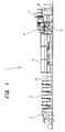
  • FIG. 1 is a general external view of a web rotary press equipped with a delivery apparatus according to an embodiment of the present invention; FIG. 2 is a schematic view of the delivery apparatus according to the embodiment of the present invention; FIG. 3 is a schematic view of a delivery conveyor constituting the delivery apparatus according to the embodiment of the present invention; FIG. 4 is a control block diagram of a delivery apparatus and a delivery method according to a first embodiment of the present invention; FIG. 5 is a flow chart for the delivery apparatus and the delivery method according to the first embodiment of the present invention; FIG. 6 is a control block diagram of a delivery apparatus and a delivery method according to a second embodiment of the present invention; FIG. 7 is a flow chart for the delivery apparatus and the delivery method according to the second embodiment of the present invention; FIG. 8 is a control block diagram of a delivery apparatus and a delivery method according to a third embodiment of the present invention; and FIG. 9 is a flow chart for the delivery apparatus and the delivery method according to the third embodiment of the present invention.
  • Detailed Description
    FIG. 1 shows a web rotary press equipped with a delivery apparatus according to an embodiment of the present invention. FIG. 2 shows the delivery apparatus according to the embodiment of the present invention. A web rotary press 1 shown in FIG. 1 is composed of a feeding device 2, a plurality of printing units 3, a dryer 4, a cooling device 5, a web path device 6, a drag device 7, a folder 8, etc. A delivery conveyor 9 is installed adjacent the folder 8. These devices 2 to 8 are connected together by a power transmission mechanism (not shown) . Thus, these devices 2 to 8 are interlocked by a drive device, which drives the entire printing press 1, via the power transmission mechanism.
    The feeding device 2 transports a web 10, wound in roll form, to the printing units 3 located downstream. The printing units 3 are devices for printing the web 10 transported past the feeding device 2. The dryer 4 is a device for heat-drying the web 10 which has been printed through the printing units 3. The cooling device 5 is a device for cooling the web 10 which has passed through the dryer 4. The web path device 6 is a device for changing the direction of the web 10 in order to control the position and tension of the web 10. The drag device 7 is a device for doubling the web 10 in a width direction.
    The folder 8 is a device for cutting and folding the web 10 after drying and cooling. For example, the folder 8 is a device for cutting the web to a predetermined length by a cut-off cylinder (not shown), parallel-folding a cut signature parallel in a lengthwise direction by a folding cylinder (not shown) , or doubling a parallel-folded signature in a perpendicular direction by a chopper (not shown). The folder 8 of various structures is available according to combinations of cutting and folding.
    A component of a delivery apparatus placed in the folder 8 is the delivery conveyor 9. A delivery apparatus 11 shown in FIG. 2 is composed of the delivery conveyor 9 and a fan wheel 12. In the drawing, the direction of transport of the delivery conveyor 9 and the direction of rotation of the fan wheel 12 are indicated by arrows.
    A table 13 has both ends supported by a frame 14. Transport belts 16, which consist of upper and lower belts paired up, are passed over the table 13. Plural sets of the transport belts 16 interpose a signature 15 therebetween, and transport the signature 15. Two folding rolls 17a, 17b are placed below a middle portion of the table 13. Delivery belts 18a, 18b are passed over the folding rolls 17a, 17b, respectively. The delivery belt 18a is also passed over rollers 19a and 19b, and the delivery belt 18b is also passed over rollers 19c and 19d. The directions of rotations of the folding rolls 17a, 17b are as shown in the drawing, and the delivery belts 18a, 18b are also rotated in the same directions as these directions of rotations.
    The fan wheel 12 is installed below the delivery belts 18a, 18b, and the delivery conveyor 9 is installed further below the fan wheel 12. Guides 20a, 20b are installed, beginning at the roller 19b, to extend toward the delivery belt 9. A stopper 21 is mounted below the fan wheel 12.
    Because of the above-described features, the signature 15 is chopper-folded by a chopper (not shown) located above the table 13. The chopper-folded signature 15 is passed above the table 13, inserted between the rolls 17a and 17b, interposed between the delivery belts 18a and 18b, and discharged downward. The discharged signature 15 is transported to a holding portion 12a of the fan wheel 12 along the guides 20a, 20b. The signature 15, held by the holding portion 12a, is brought into contact with the stopper 21 in accordance with the rotation of the fan wheel 12, and discharged to the delivery conveyor 9. The discharged signature 15 is delivered to a predetermined position by the delivery conveyor 9.
    FIG. 3 shows a schematic view of the delivery conveyor constituting the delivery apparatus according to the embodiment of the present invention illustrated in FIG. 2. The delivery conveyor 9 is connected to a delivery conveyor drive motor 22. A delivery conveyor drive motor rotary encoder 23 is annexed to the delivery conveyor drive motor 22. The delivery conveyor drive motor 22 and the delivery conveyor drive motor rotary encoder 23 are connected to a delivery conveyor control device 24. The delivery conveyor control device 24 is connected to a main unit control device 25 which controls the printing press 1. A main unit motor 26, and a main unit motor rotary encoder 27 annexed to the main unit motor 26 are connected to the main unit control device 25. The main unit motor 26 is connected to the printing press 1. Thus, the printing press 1 and the delivery conveyor 9 can be driven in an interlocked manner.
    Embodiment 1
    FIG. 4 is a control block diagram of a delivery apparatus and a delivery method according to a first embodiment of the present invention.
    The delivery conveyor control device 24 comprises a CPU 28, an ROM 29, and an RAM 30, and also includes a memory 31 for a main unit speed for switching between continuous and intermittent operations, a current main unit speed memory 32, a main unit speed-delivery conveyor drive motor continuous drive speed conversion table memory 33 , amain unit speed-delivery conveyor drive motor intermittent drive time conversion table memory 34, a main unit speed-delivery conveyor drive motor intermittent stop time conversion table memory 35, a delivery conveyor drive motor continuous drive speed memory 36, a delivery conveyor drive motor intermittent drive time memory 37, and a delivery conveyor drive motor intermittent stop time memory 38. These devices, these memories, input/output devices 39a to 39c, and an interface 40a are connected together by a bus-line BUS 52.
    An input device 41, such as a start switch or a key board, a display device 42, such as a display, and an output device 43, such as a printer, are connected to the input/output device 39a. The main unit control device 25 is connected to the interface 40a via an interface 40b. The main unit motor rotary encoder 27 is connected to the input/output device 39b via an A/D converter 44 and an F/V converter 45. The delivery conveyor drive motor 22 and the delivery conveyor drive motor rotary encoder 23 are connected to the input/output device 39c via a delivery conveyor drive motor driver 46.
    According to the above-described features, if the drive speed of the printing press 1 is higher than a predetermined drive speed, the delivery conveyor drive motor 22 can be continuously driven. If the drive speed of the printing press 1 is lower than the predetermined drive speed, the delivery conveyor drive motor 22 can be intermittently driven.
    Moreover, the drive speed of the delivery conveyor drive motor 22, when intermittently driven, is the minimum drive speed of the delivery conveyor drive motor 22.
    Furthermore, when the delivery conveyor drive motor 22 is to be intermittently driven, the drive time and the stop time of the delivery conveyor drive motor 22 are computed by the aforementioned CPU 28 based on the drive speed of the printing press 1.
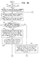
    Drive control over the delivery conveyor drive motor 22 for the delivery conveyor 9 will be explained along a flow chart shown in FIG. 5.
    In Step Sa1, it is determined whether the start switch is ON. If ON, the program proceeds to Step Sa2. In Step Sa2, the main unit speed for switching between continuous and intermittent operations is loaded from the memory 31 for the main unit speed for switching between continuous and intermittent operations. In Step Sa3, a signal on the drive speed of the printing press 1 outputted from the A/D converter 44 connected to the main unit motor rotary encoder 27 is loaded. In Step Sa4, the CPU 28 computes the drive speed of the printing press 1 from the signal loaded in Step Sa3, and stores the computed results in the current main unit speed memory 32.
    In Step Sa5, it is determined whether the current main unit speed computed in Step Sa4 is lower than the main unit speed for switching between continuous and intermittent operations that was loaded in Step Sa2. That is, a determination is made as to whether the drive speed of the printing press 1 is lower than a predetermined speed. If it is lower, the program proceeds to Step Sa6. If not, the program proceeds to Step Sa19.
    In Step Sa6, the CPU 28 finds the intermittent drive time of the delivery conveyor drive motor 22 with the use of the main unit speed-delivery conveyor drive motor intermittent drive speed conversion table memory 34 based on the current main unit speed computed in Step Sa4. The results are stored in the delivery conveyor drive motor intermittent drive time memory 37.
    In Step Sa7, the CPU 28 finds the intermittent stop time of the delivery conveyor drive motor 22 with the use of the main unit speed-delivery conveyor drive motor intermittent stop time conversion table memory 35 based on the current main unit speed computed in Step Sa4. The results are stored in the delivery conveyor drive motor intermittent stop time memory 38.
    In Step Sa8, the CPU 28 issues a minimum speed drive command to the delivery conveyor drive motor driver 46 to output a signal to the delivery conveyor drive motor 22 and drive it at the minimum speed.
    In Step Sa9, counting of the internal clock is started. In Step Sa10, it is determined whether the internal clock is ON. If ON, the program proceeds to Step Sa11. In Step Sa11, 1 is added to the counted value of the internal clock.
    In Step Sa12, it is determined whether the counted value of the internal clock is equal to the intermittent drive time of the delivery conveyor drive motor 22 found in Step Sa6. If it is equal, the program proceeds to Step Sa13. If it is not equal, the program returns to Step Sa10 to continue processing in the same manner.
    In Step Sa13, the CPU 28 issues a stop command to the delivery conveyor drive motor driver 46 to output a signal to the delivery conveyor drive motor 22 and stop it.
    In Step Sa14, counting of the internal clock is started. In Step Sa15, it is determined whether the internal clock is ON. If ON, the program proceeds to Step Sa16. In Step Sa16, 1 is added to the counted value of the internal clock.
    In Step Sa17, it is determined whether the counted value of the internal clock is equal to the intermittent stop time of the delivery conveyor drive motor 22 found in Step Sa7. If it is equal, the program proceeds to Step Sa18. If it is not equal, the program returns to Step Sa15 to continue processing in the same manner.
    In Step Sa18, it is determined whether the stop switch is ON. If ON, the control ends. If not ON, the program returns to Step Sa3 to continue processing.
    If the program proceeds from Step Sa5 to Step Sa19 , on the other hand, the CPU 28 obtains the continuous drive speed of the delivery conveyor drive motor 22 with the use of the main unit speed-delivery conveyor drive motor continuous drive speed conversion table memory 33 based on the current main unit speed computed in Step Sa4. The CPU 28 stores the results in the delivery conveyor drive motor continuous drive speed memory 36. In Step Sa20, the CPU 28 issues a drive command for drive at the obtained continuous drive speed to the delivery conveyor drive motor driver 46, thereby driving the delivery conveyor drive motor 22 at the obtained continuous drive speed.
    In the present embodiment, as described above, if the printing press 1 operates at a speed higher than a certain drive speed, the delivery conveyor 9 is continuously driven. If the printing press 1 operates at a speed lower than the certain drive speed, the delivery conveyor 9 is intermittently driven. During the intermittent driving of the delivery conveyor 9 , the drive speed of the delivery conveyor 9 is a minimum speed. Moreover, the drive speed and the stop time of the delivery conveyor 9 are determined in accordance with the drive speed of the printing press 1. Thus, the delivery conveyor 9 can have a variable speed range. For example, the delivery conveyor drive motor 22 is an inverter motor capable of convenient speed adjustment, and is of a general type having a rotational speed in a variable range of 100 to 2,500 rpm. That is, the delivery conveyor 9 can be driven with a speed variable range of 25 times or less. Thus, it is possible to provide a delivery apparatus of a printing press, which has a delivery conveyor driven at a low speed to a high speed with the use of an inexpensive small motor, and a delivery method using the delivery apparatus.
    Embodiment 2
    FIG. 6 is a control block diagram of a delivery apparatus and a delivery method according to a second embodiment of the present invention. This embodiment involves changes in the features of the delivery conveyor control device 24.
    The delivery conveyor control device 24 comprises a CPU 28, an ROM 29, and an RAM 30, and also includes a memory 31 for a main unit speed for switching between continuous and intermittent operations, a current main unit speed memory 32, a main unit speed-delivery conveyor drive motor continuous drive speed conversion table memory 33, amain unit speed-delivery conveyor drive motor intermittent drive time conversion table memory 34, a delivery conveyor drive motor continuous drive speed memory 36, a delivery conveyor drive motor intermittent drive time memory 37, and a memory 47 for a main unit phase for complete discharge of a signature from a fan wheel. These devices, these memories, input/output devices 39a to 39e, and an interface 40a are connected together by a bus-line BUS 52.
    An input device 41, such as a start switch or a key board, a display device 42, such as a display, and an output device 43, such as a printer, are connected to the input/output device 39a. The main unit control device 25 is connected to the interface 40a via an interface 40b. The main unit motor rotary encoder 27 is connected to the input/output device 39b via an A/D converter 44 and an F/V converter 45. A main unit phase detection counter 48 is connected to the input/output device 39d. The main unit phase detection counter 48 is connected to the main unit motor rotary encoder 27 via a flip-flop circuit 49. A detection signal (clock pulse) of the main unit motor rotary encoder 27 is entered into the main unit phase detection counter 48. The main unit phase detection counter 48 and the flip-flop circuit 49 are connected to the input/output device 39e. The delivery conveyor drive motor 22 and the delivery conveyor drive motor rotary encoder 23 are connected to the input/output device 39c via a delivery conveyor drive motor driver 46.
    According to the above-described features, when the delivery conveyor drive motor 22 is to be intermittently driven, the drive time of the delivery conveyor drive motor 22 is computed by the CPU 28 based on the drive speed of the printing press 1, and when the signature 15 is completely discharged to the delivery conveyor 9, driving of the delivery conveyor drive motor 22 is started.
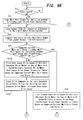
    Drive control over the delivery conveyor drive motor 22 for the delivery conveyor 9 will be explained along a flow chart shown in FIG. 7.
    In Step Sb1, it is determined whether the start switch is ON. If ON, the program proceeds to Step Sb2. In Step Sb2, the main unit speed for switching between continuous and intermittent operations is loaded from the memory 31 for the main unit speed for switching between continuous and intermittent operations. In Step Sb3, a signal on the drive speed of the printing press 1 outputted from the A/D converter 44 connected to the main unit motor rotary encoder 27 is loaded. In Step Sb4, the CPU 28 computes the drive speed of the printing press 1 from the signal loaded in Step Sb3, and stores the computed results in the current main unit speed memory 32.
    In Step Sb5, it is determined whether the current main unit speed computed in Step Sb4 is lower than the main unit speed for switching between continuous and intermittent operations that was loaded in Step Sb2. That is, a determination is made as to whether the drive speed of the printing press 1 is lower than a predetermined speed. If it is lower, the program proceeds to Step Sb6. If not, the program proceeds to Step Sb19.
    In Step Sb6, the CPU 28 finds the intermittent drive time of the delivery conveyor drive motor 22 with the use of the main unit speed-delivery conveyor drive motor intermittent drive time conversion table memory 34 based on the current main unit speed computed in Step Sb4. The results are stored in the delivery conveyor drive motor intermittent drive time memory 37.
    In Step Sb7, the phase of the main unit, in which the signature 15 is completely discharged from the fan wheel 12, is read from the memory 47 for a main unit phase for complete discharge of the signature. In Step Sb8, a counted value is read from the main unit phase detection counter 48.
    In Step Sb9, it is determined whether the counted value read in Step Sb8 is equal to the main unit phase for complete discharge of the signature 15 from the fan wheel 12 that was read in Step Sb7. If it is equal, the program proceeds to Step Sb10. If it is not equal, the program returns to Step Sb8 to continue processing.
    In Step Sb10, a reset signal is outputted to the main unit phase detection counter 48 and the flip-flop circuit 49. In Step Sb11, the CPU 28 issues a minimum speed drive command to the delivery conveyor drive motor driver 46 to output a signal to the delivery conveyor drive motor 22 and drive it at the minimum speed.
    In Step Sb12, counting of the internal clock is started. In Step Sb13, it is determined whether the internal clock is ON. If ON, the program proceeds to Step Sb14. In Step Sb14, 1 is added to the counted value of the internal clock.
    In Step Sb15 , it is determined whether the counted value of the internal clock is equal to the intermittent drive time of the delivery conveyor drive motor 22 found in Step Sb6. If it is equal, the program proceeds to Step Sb16. If it is not equal, the program returns to Step Sb13 to continue processing in the same manner.
    In Step Sb16, the CPU 28 issues a stop command to the delivery conveyor drive motor driver 46 to output a signal to the delivery conveyor drive motor 22 and stop it. In Step Sb18 , it is determined whether the stop switch is ON. If ON, the control ends. If not ON, the program returns to Step Sb3 to continue processing.
    If the program proceeds from Step Sb5 to Step Sb19, on the other hand, the CPU 28 obtains the continuous drive speed of the delivery conveyor drive motor 22 with the use of the main unit speed-delivery conveyor drive motor continuous drive speed conversion table memory 33 based on the current main unit speed computed in Step Sb4. The CPU 28 stores the results in the delivery conveyor drive motor continuous drive speed memory 36. In Step Sb20, the CPU 28 issues a drive command for drive at the obtained continuous drive speed to the delivery conveyor drive motor driver 46, thereby driving the delivery conveyor drive motor 22 at the obtained continuous drive speed.
    In the present embodiment, as described above, the drive time of the delivery conveyor 9 is determined based on the drive speed of the printing press 1, and after the signature 15 is completely discharged to the delivery conveyor 9, driving of the delivery conveyor 9 is started. Thus, the signature 15 is stably discharged to the delivery conveyor 9, and the intermittent drive time and the intermittent stop time of the delivery conveyor 9 can be controlled reliably.
    Embodiment 3
    FIG. 8 is a control block diagram of a delivery apparatus and a delivery method according to a third embodiment of the present invention. This embodiment also involves changes in the features of the delivery conveyor control device 24.
    The delivery conveyor control device 24 comprises a CPU 28, an ROM 29, and an RAM 30, and also includes a memory 31 for a main unit speed for switching between continuous and intermittent operations, a current main unit speed memory 32 , a main unit speed-delivery conveyor drive motor continuous drive speed conversion table memory 33 , amain unit speed-delivery conveyor drivemotor intermittent drive speed conversion table memory 50, a main unit speed-delivery conveyor drive motor intermittent drive time conversion table memory 34, a delivery conveyor drive motor intermittent drive speed memory 51, a delivery conveyor drive motor continuous drive speed memory 36, a delivery conveyor drive motor intermittent drive time memory 37, and a memory 47 for a main unit phase for complete discharge of a signature from a fan wheel. These devices, these memories, input/output devices 39a to 39e, and an interface 40a are connected together by a bus-line BUS 52.
    An input device 41, such as a start switch or a key board, a display device 42, such as a display, and an output device 43, such as a printer, are connected to the input/output device 39a. The main unit control device 25 is connected to the interface 40a via an interface 40b. The main unit motor rotary encoder 27 is connected to the input/output device 39b via an A/D converter 44 and an F/V converter 45. A main unit phase detection counter 48 is connected to the input/output device 39d. The main unit phase detection counter 48 is connected to the main unit motor rotary encoder 27 via a flip-flop circuit 49. A detection signal (clock pulse) of the main unit motor rotary encoder 27 is entered into the main unit phase detection counter 48. The main unit phase detection counter 48 and the flip-flop circuit 49 are connected to the input/output device 39e. The delivery conveyor drive motor 22 and the delivery conveyor drive motor rotary encoder 23 are connected to the input/output device 39c via a delivery conveyor drive motor driver 46.
    According to the above-described features, when the delivery conveyor drive motor 22 is to be intermittently driven, the drive speed and the drive time of the delivery conveyor drive motor 22 are computed by the CPU 28 based on the drive speed of the printing press 1, and when the signature 15 is completely discharged to the delivery conveyor 9, driving of the delivery conveyor drive motor 22 is started.
    In the above-described case, when the delivery conveyor drive motor 22 is to be intermittently driven, the drive time of the delivery conveyor drive motor 22 is a period of time from complete discharge of the signature 15 to the delivery conveyor 9 until start of discharge of a next signature 15 to the delivery conveyor 9.
    Drive control over the delivery conveyor drive motor 22 for the delivery conveyor 9 will be explained along a flow chart shown in FIG. 9.
    In Step Sc1, it is determined whether the start switch is ON. If ON, the program proceeds to Step Sc2. In Step Sc2, the main unit speed for switching between continuous and intermittent operations is loaded from the memory 31 for a main unit speed for switching between continuous and intermittent operations. In Step Sc3, a signal on the drive speed of the printing press 1 outputted from the A/D converter 44 connected to the main unit motor rotary encoder 27 is loaded. In Step Sc4, the CPU 28 computes the drive speed of the printing press 1 from the signal loaded in Step Sc3, and stores the computed results in the current main unit speed memory 32.
    In Step Sc5, it is determined whether the current main unit speed computed in Step Sc4 is lower than the main unit speed for switching between continuous and intermittent operations that was loaded in Step Sc2. That is, a determination is made as to whether the drive speed of the printing press 1 is lower than a predetermined speed. If it is lower, the program proceeds to Step Sc6. If not, the program proceeds to Step Sc19.
    In Step Sc6, the CPU 28 finds the intermittent drive speed of the delivery conveyor drive motor 22 with the use of the main unit speed-delivery conveyor drive motor intermittent drive speed conversion table memory 50 based on the current main unit speed computed in Step Sc4. The results are stored in the delivery conveyor drive motor intermittent drive speed memory 51.
    In Step Sc7, the CPU 28 finds the intermittent drive time of the delivery conveyor drive motor 22 with the use of the main unit speed-delivery conveyor drive motor intermittent drive time conversion table memory 34 based on the current main unit speed computed in Step Sc4. The results are stored in the delivery conveyor drive motor intermittent drive time memory 37.
    In Step Sc8, the phase of the main unit, in which the signature 15 is completely discharged from the fan wheel 12, is read from the memory 47 for main unit phase for complete discharge of the signature. In Step Sc9, a counted value is read from the main unit phase detection counter 48.
    In Step Sc10, it is determined whether the counted value read in Step Sc9 is equal to the main unit phase for complete discharge of the signature 15 from the fan wheel 12 that was read in Step Sc8. If it is equal, the program proceeds to Step Se11. If it is not equal, the program returns to Step Sc9 to continue processing.
    In Step Se11, a reset signal is outputted to the main unit phase detection counter 48 and the flip-flop circuit 49. In Step Sc12, the CPU 28 issues a drive command to the delivery conveyor drive motor driver 46 for driving of the delivery conveyor drive motor at the intermittent drive speed found in Step Sc6, thereby outputting a signal to the delivery conveyor drive motor 22 and driving it at that speed.
    In Step Sc13, counting of the internal clock is started. In Step Sc14, it is determined whether the internal clock is ON. If ON, the program proceeds to Step Sc15. In Step Sc15, 1 is added to the counted value of the internal clock.
    In Step Sc16, it is determined whether the counted value of the internal clock is equal to the intermittent drive time of the delivery conveyor drive motor 22 found in Step Sc7. If it is equal, the program proceeds to Step Sc17. If it is not equal, the program returns to Step Sc14 to continue processing in the same manner.
    In Step Sc17, the CPU 28 issues a stop command to the delivery conveyor drive motor driver 46 to output a signal to the delivery conveyor drive motor 22 and stop it. In Step Sc18 , it is determinedwhether the stop switch is ON. If ON, the control ends. If not ON, the program returns to Step Sc3 to continue processing.
    If the program proceeds from Step Sc5 to Step Sc19 , on the other hand, the CPU 28 obtains the continuous drive speed of the delivery conveyor drive motor 22 with the use of the main unit speed-delivery conveyor drive motor continuous drive speed conversion table memory 33 based on the current main unit speed computed in Step Sc4. The CPU 28 stores the results in the delivery conveyor drive motor continuous drive speed memory 36. In Step Sc20, the CPU 28 issues a drive command for drive at the obtained continuous drive speed to the delivery conveyor drive motor driver 46, thereby driving the delivery conveyor drive motor 22 at the obtained continuous drive speed.
    In the present embodiment, as described above, the drive speed and the drive time of the delivery conveyor 9 are determined based on the drive speed of the printing press 1, and after the signature 15 is completely discharged to the delivery conveyor 9, driving of the delivery conveyor 9 is started. Moreover, the drive time of the delivery conveyor in this case is a period of time from complete discharge of the signature 15 to the delivery conveyor 9 until start of discharge of a next signature 15 to the delivery conveyor 9. Thus, the delivery conveyor 9 can be driven in agreement with the discharge cycle of the signature 15, and the delivery conveyor 9 can be stopped until discharge of the next signature 15. Hence, the signature 15 is stably discharged to the delivery conveyor 9. Besides, by controlling the intermittent driving of the delivery conveyor 9, the signatures 15 can be discharged at predetermined intervals even with the use of an inexpensive small motor.
    As noted above, the delivery conveyor is usable as a delivery conveyor of a printing press using an inexpensive, small motor.
    While the present invention has been described by the above embodiments, it is to be understood that the invention is not limited thereby, but may be varied or modified in many other ways. Such variations or modifications are not to be regarded as a departure from the spirit and scope of the invention, and all such variations and modifications as would be obvious to one skilled in the art are intended to be included within the scope of the appended claims.

    Claims (14)

    1. A delivery apparatus (11) having a delivery conveyor (9) for receiving and transporting a printing product (15) discharged from a printing press (1),
      characterized in that
         said delivery conveyor (9) is continuously driven if a drive speed of said printing press (1) is higher than a predetermined speed, and
         said delivery conveyor (9) is intermittently driven if said drive speed of said printing press (1) is lower than said predetermined speed.
    2. The delivery apparatus according to claim 1,
      characterized in that
         a drive speed of said delivery conveyor (9) when intermittently driven is a minimum drive speed of said delivery conveyor (9).
    3. The delivery apparatus according to claim 1,
      characterized in that
         a drive time and a stop time of said delivery conveyor (9) when intermittently driven are determined based on said drive speed of said printing press (1).
    4. The delivery apparatus according to claim 1,
      characterized in that
         when said delivery conveyor (9) is to be intermittently driven, a drive time of said delivery conveyor (9) is determined based on said drive speed of said printing press (1), and
         at a time when said printing product (15) is completely discharged to said delivery conveyor (9), driving of said delivery conveyor (9) is started.
    5. The delivery apparatus according to claim 1,
      characterized in that
         when said delivery conveyor (9) is to be intermittently driven, a drive speed and a drive time of said delivery conveyor (9) are determined based on said drive speed of said printing press (1), and
         at a time when said printing product (15) is completely discharged to said delivery conveyor (9), driving of said delivery conveyor (9) is started.
    6. The delivery apparatus according to claim 5,
      characterized in that
         when said delivery conveyor (9) is to be intermittently driven, said drive time of said delivery conveyor (9) is a period of time from complete discharge of said printing product (15) to said delivery conveyor (9) until start of discharge of a next printing product (15) to said delivery conveyor (9).
    7. The delivery apparatus according to claim 1,
      characterized by
         a drive device (22) for driving said delivery conveyor (9),
      and characterized in that
         a maximum drive speed of said drive device (22) is not more than 25 times a minimum drive speed of said drive device (22).
    8. A delivery method for receiving and transporting a printing product (15), which is discharged from a printing press (1), by a delivery conveyor (9),
      characterized by:
      continuously driving said delivery conveyor (9) if a drive speed of said printing press (1) is higher than a predetermined speed, and
      intermittently driving said delivery conveyor (9) if said drive speed of said printing press (1) is lower than said predetermined speed,
      thereby delivering said printing product (15).
    9. The delivery method according to claim 8,
      characterized in that
         a drive speed of said delivery conveyor (9) when intermittently driven is a minimum drive speed of said delivery conveyor (9).
    10. The delivery method according to claim 8,
      characterized by:
      determining a drive time and a stop time of said delivery conveyor (9) based on said drive speed of said printing press (1) when said delivery conveyor (9) is to be intermittently driven.
    11. The delivery method according to claim 8,
      characterized by:
      determining a drive time of said delivery conveyor (9) based on said drive speed of said printing press (1) when said delivery conveyor (9) is to be intermittently driven; and
      starting driving of said delivery conveyor (9) at a time when said printing product (15) is completely discharged to said delivery conveyor (9).
    12. The delivery method according to claim 8,
      characterized by:
      determining a drive speed and a drive time of said delivery conveyor (9) based on said drive speed of said printing press (1) when said delivery conveyor (9) is to be intermittently driven; and
      starting driving of said delivery conveyor (9) at a time when said printing product (15) is completely discharged to said delivery conveyor (9).
    13. The delivery method according to claim 12,
      characterized in that
         said drive time of said delivery conveyor (9) when said delivery conveyor (9) is intermittently driven is a period of time from complete discharge of said printing product (15) to said delivery conveyor (9) until start of discharge of a next printing product (15) to said delivery conveyor (9).
    14. The delivery method according to claim 8,
      characterized in that
         a maximum drive speed of said delivery conveyor (9) is not more than 25 times a minimum drive speed of said delivery conveyor (9).
    EP04022436A 2003-10-01 2004-09-21 Delivery apparatus and delivery method Withdrawn EP1520816A3 (en)

    Applications Claiming Priority (2)

    Application Number Priority Date Filing Date Title
    JP2003342789A JP4230874B2 (en) 2003-10-01 2003-10-01 Paper discharge device and method
    JP2003342789 2003-10-01

    Publications (2)

    Publication Number Publication Date
    EP1520816A2 true EP1520816A2 (en) 2005-04-06
    EP1520816A3 EP1520816A3 (en) 2009-03-11

    Family

    ID=34309101

    Family Applications (1)

    Application Number Title Priority Date Filing Date
    EP04022436A Withdrawn EP1520816A3 (en) 2003-10-01 2004-09-21 Delivery apparatus and delivery method

    Country Status (4)

    Country Link
    US (1) US7377510B2 (en)
    EP (1) EP1520816A3 (en)
    JP (1) JP4230874B2 (en)
    CN (1) CN1603218B (en)

    Families Citing this family (1)

    * Cited by examiner, † Cited by third party
    Publication number Priority date Publication date Assignee Title
    CN103588003A (en) * 2013-11-20 2014-02-19 上海航星机械(集团)有限公司 Sacking output mechanism transmission method

    Family Cites Families (36)

    * Cited by examiner, † Cited by third party
    Publication number Priority date Publication date Assignee Title
    US3945635A (en) * 1974-07-19 1976-03-23 Pitney-Bowes, Inc. Power stacker
    AT333193B (en) * 1974-12-23 1976-11-10 Gao Ges Automation Org DISCHARGE AND STACKING DEVICE FOR FLAT TRANSPORTED GOODS, SUCH AS PAPER SHEETS, DOCUMENTS AND THE LIKE
    DE7619535U1 (en) * 1976-06-19 1976-10-07 Gustav Weyland Kg, 6740 Landau SHEET DELIVERY DEVICE FOR ROTARY PRINTING MACHINES
    US4067568A (en) * 1976-07-19 1978-01-10 Pitney-Bowes, Inc. Document feeding and stacking apparatus
    US4088314A (en) * 1977-04-22 1978-05-09 Eastman Kodak Company Synchronous stacking device
    DE2756223C2 (en) * 1977-12-16 1982-12-30 GAO Gesellschaft für Automation und Organisation mbH, 8000 München Method for controlling the infeed of goods to be transported into a spiral stacker and device for carrying out the method
    US4361318A (en) * 1979-07-09 1982-11-30 Stobb, Inc. Apparatus and method for controlling sheet stacker speed
    JPS57138847U (en) * 1981-02-24 1982-08-30
    US4638993A (en) * 1981-06-29 1987-01-27 Ncr Corporation Position control for a stacker wheel
    JPS59182156A (en) * 1983-03-31 1984-10-16 Toshiba Corp Paper-sheet recovering apparatus
    US4667951A (en) * 1983-08-23 1987-05-26 Canon Kabushiki Kaisha Original feeding apparatus
    DE3612021A1 (en) * 1986-04-10 1987-10-15 Will E C H Gmbh & Co DEVICE FOR WORKING CYCLE TRANSPORTATION OF SHEET PAGES TO A FOLLOW-UP PROCESSING MACHINE, FOR EXAMPLE TO A PACKING MACHINE
    SE458358B (en) * 1987-05-21 1989-03-20 Pmb Vector Ab RECEIVING DEVICE FOR SHIPPING TRANSFERS COLLECTING COLLECTION OF SHEETS FOR CONTINUOUS TRANSPORTATION
    EP0316477A1 (en) * 1987-11-19 1989-05-24 Drg (Uk) Limited Method and apparatus for handling leaves of sheet material
    JP3245746B2 (en) * 1989-12-08 2002-01-15 エス イー ゲー シュバイツェリッシェ インズストリー‐ゲゼルシャフト Column forming device for articles, especially chocolate bars
    US5186336A (en) * 1991-01-22 1993-02-16 Electrocom Automation L.P. Product sorting apparatus
    US5253860A (en) * 1991-08-06 1993-10-19 Ricoh Company, Ltd. Finisher for an image forming apparatus
    GB9207929D0 (en) * 1992-04-10 1992-05-27 Ncr Int Inc Apparatus for loading sheets into a receptacle
    DE69421783T2 (en) * 1993-09-20 2000-07-06 Kabushiki Kaisha Toshiba, Kawasaki Device for checking sheet materials and transport device therefor
    US5501147A (en) * 1993-10-05 1996-03-26 Precision Screen Machines, Inc. Automatic doffing system
    IT1285693B1 (en) * 1996-05-08 1998-06-18 Azionaria Costruzioni Acma Spa METHOD AND DEVICE FOR THE ORDINARY FEEDING OF PRODUCTS RECEIVED IN BULK
    JPH1111769A (en) 1997-06-26 1999-01-19 Komori Corp Delivery device
    JP3556848B2 (en) * 1998-12-21 2004-08-25 三菱重工業株式会社 Paper ejection pitch switching device for folder
    US6394445B1 (en) * 1998-12-30 2002-05-28 Quad/Tech, Inc. Apparatus for slowing down and guiding a signature and method for doing the same
    DE19904853A1 (en) * 1999-02-05 2000-08-17 Siemens Nixdorf Banking Syst Method and device for forming a bundle of single sheets
    JP3032763B1 (en) * 1999-06-17 2000-04-17 株式会社東京機械製作所 Paper feed unit with web paper running tension control device for rotary press
    US6672586B2 (en) * 1999-07-23 2004-01-06 Canon Kabushiki Kaisha Sheet processing apparatus and method of controlling same, sheet processing method, and storage media therefor
    US6712356B2 (en) * 2000-02-09 2004-03-30 Mars Incorporated Self aligning transport mechanism for media of variable media widths
    US6494447B2 (en) * 2000-06-13 2002-12-17 Giesecke & Devrient America, Inc. Stacker wheel control apparatus and method utilizing start-stop synchronization
    JP2002003067A (en) * 2000-06-19 2002-01-09 Nec Corp Printer
    DE10030226A1 (en) * 2000-06-20 2002-01-03 Giesecke & Devrient Gmbh Sheet material stacking device and method for controlling the entry of sheet material into a stacker wheel
    JP4791631B2 (en) * 2000-12-26 2011-10-12 株式会社東芝 Paper sheet processing equipment
    ITBO20010394A1 (en) * 2001-06-21 2002-12-21 Azionaria Costruzioni Acma Spa UNIT FOR THE SUPPLY OF AN ORDERED SUCCESSION OF PRODUCTS TO AN UNLOADING STATION
    JP3622849B2 (en) * 2001-12-06 2005-02-23 株式会社東京機械製作所 Jam detection device for folding device
    US6644645B2 (en) * 2002-01-10 2003-11-11 Gbr Systems Corporation Stack control mechanism
    JP3679391B2 (en) * 2002-10-22 2005-08-03 株式会社東京機械製作所 Folding machine delivery device

    Also Published As

    Publication number Publication date
    EP1520816A3 (en) 2009-03-11
    JP4230874B2 (en) 2009-02-25
    US7377510B2 (en) 2008-05-27
    JP2005104686A (en) 2005-04-21
    US20050073086A1 (en) 2005-04-07
    CN1603218B (en) 2010-05-05
    CN1603218A (en) 2005-04-06

    Similar Documents

    Publication Publication Date Title
    JP5255110B2 (en) Paper post-processing device
    US5826869A (en) High throughput document-processing machine having dynamic speed control
    EP0522408A1 (en) Folding machine, particularly for signatures
    JP2008156113A (en) Paper post-processing apparatus and blade control method for paper post-processing apparatus
    EP1520816A2 (en) Delivery apparatus and delivery method
    US20110058875A1 (en) Sheet folding apparatus and image formation system provided with the apparatus
    US9193556B2 (en) Sheet folding apparatus and image forming system
    CN114929487B (en) Bindery that stops conveying components at a processing station and disengages conveying components at other processing stations
    JP2008308341A (en) Paper discharge device and method
    US9346256B2 (en) Method for producing printed products
    EP3501838B1 (en) Saddle-stitch book binding system
    JP3878727B2 (en) Collating device
    JP7067808B2 (en) Saddle stitch binding system and its control method
    NL1032054C2 (en) Method and buffer station for buffering documents.
    JP2635254B2 (en) Banknote organizer
    JP2000301493A (en) Sheet punching equipment
    JP2761570B2 (en) Media processing device
    JP3378650B2 (en) Automatic document feeder
    EP1871610A2 (en) Method of transporting sheets in a digital printing machine
    JP4758267B2 (en) Sheet post-processing apparatus and image forming apparatus
    JPH11263527A (en) Image forming system
    US20110293389A1 (en) Method and system for producing a printed product
    JPH04125253A (en) collation system
    JPH09235039A (en) Document feeding type image reading device
    JPH0735038B2 (en) Ticket issuing device

    Legal Events

    Date Code Title Description
    PUAI Public reference made under article 153(3) epc to a published international application that has entered the european phase

    Free format text: ORIGINAL CODE: 0009012

    AK Designated contracting states

    Kind code of ref document: A2

    Designated state(s): AT BE BG CH CY CZ DE DK EE ES FI FR GB GR HU IE IT LI LU MC NL PL PT RO SE SI SK TR

    AX Request for extension of the european patent

    Extension state: AL HR LT LV MK

    PUAL Search report despatched

    Free format text: ORIGINAL CODE: 0009013

    AK Designated contracting states

    Kind code of ref document: A3

    Designated state(s): AT BE BG CH CY CZ DE DK EE ES FI FR GB GR HU IE IT LI LU MC NL PL PT RO SE SI SK TR

    AX Request for extension of the european patent

    Extension state: AL HR LT LV MK

    17P Request for examination filed

    Effective date: 20090317

    AKX Designation fees paid

    Designated state(s): AT BE BG CH CY CZ DE DK EE ES FI FR GB GR HU IE IT LI LU MC NL PL PT RO SE SI SK TR

    17Q First examination report despatched

    Effective date: 20100304

    STAA Information on the status of an ep patent application or granted ep patent

    Free format text: STATUS: THE APPLICATION IS DEEMED TO BE WITHDRAWN

    18D Application deemed to be withdrawn

    Effective date: 20100705