EP1520784A1 - Machine for banding groups of palletised products. - Google Patents
Machine for banding groups of palletised products. Download PDFInfo
- Publication number
- EP1520784A1 EP1520784A1 EP04425710A EP04425710A EP1520784A1 EP 1520784 A1 EP1520784 A1 EP 1520784A1 EP 04425710 A EP04425710 A EP 04425710A EP 04425710 A EP04425710 A EP 04425710A EP 1520784 A1 EP1520784 A1 EP 1520784A1
- Authority
- EP
- European Patent Office
- Prior art keywords
- film
- band
- unit
- products
- uprights
- Prior art date
- Legal status (The legal status is an assumption and is not a legal conclusion. Google has not performed a legal analysis and makes no representation as to the accuracy of the status listed.)
- Granted
Links
- 238000007789 sealing Methods 0.000 claims abstract description 12
- 238000000034 method Methods 0.000 claims description 10
- 238000002372 labelling Methods 0.000 claims description 5
- 239000004033 plastic Substances 0.000 claims description 5
- 230000003213 activating effect Effects 0.000 claims description 2
- 230000005540 biological transmission Effects 0.000 claims description 2
- 230000001360 synchronised effect Effects 0.000 claims description 2
- 238000004519 manufacturing process Methods 0.000 description 2
- 239000002985 plastic film Substances 0.000 description 2
- 229920006255 plastic film Polymers 0.000 description 2
- 230000000694 effects Effects 0.000 description 1
- 238000010348 incorporation Methods 0.000 description 1
- 239000000463 material Substances 0.000 description 1
- 238000012986 modification Methods 0.000 description 1
- 230000004048 modification Effects 0.000 description 1
- 230000003019 stabilising effect Effects 0.000 description 1
- 229920006302 stretch film Polymers 0.000 description 1
Images


Classifications
-
- B—PERFORMING OPERATIONS; TRANSPORTING
- B65—CONVEYING; PACKING; STORING; HANDLING THIN OR FILAMENTARY MATERIAL
- B65B—MACHINES, APPARATUS OR DEVICES FOR, OR METHODS OF, PACKAGING ARTICLES OR MATERIALS; UNPACKING
- B65B9/00—Enclosing successive articles, or quantities of material, e.g. liquids or semiliquids, in flat, folded, or tubular webs of flexible sheet material; Subdividing filled flexible tubes to form packages
- B65B9/02—Enclosing successive articles, or quantities of material between opposed webs
- B65B9/026—Enclosing successive articles, or quantities of material between opposed webs the webs forming a curtain
-
- B—PERFORMING OPERATIONS; TRANSPORTING
- B65—CONVEYING; PACKING; STORING; HANDLING THIN OR FILAMENTARY MATERIAL
- B65B—MACHINES, APPARATUS OR DEVICES FOR, OR METHODS OF, PACKAGING ARTICLES OR MATERIALS; UNPACKING
- B65B13/00—Bundling articles
- B65B13/02—Applying and securing binding material around articles or groups of articles, e.g. using strings, wires, strips, bands or tapes
Definitions
- the present invention relates to a machine for banding groups of palletised products, in particular palletised loads consisting of stacked products (such as, for example, but not restricted to, packs of bottles or other containers) to undergo intermediate processes and to be transported from one factory to another or from one processing station to another).
- palletised loads consisting of stacked products (such as, for example, but not restricted to, packs of bottles or other containers) to undergo intermediate processes and to be transported from one factory to another or from one processing station to another).
- Machines of this type are used to wrap a band of material around a groups of palletised products stacked to a certain height and relatively light in weight, in such a way as to stabilise the stacks during transportation or normal handling in processing lines.
- the palletised load consists of bottle crates placed side by side and stacked in two or more layers.
- the banding machine wraps a first band of plastic film at a certain height in order to hold the stack together at the most unstable part of it (usually the top of the stack) which would be the first to topple during transportation.
- Prior art machines that perform banding operations of this type comprise a portal frame whose uprights mount a pair of film rolls at a predetermined height.
- the film is unwound by suitable rollers in such a way that it is positioned transversely between the uprights to intercept the palletised load as the pallet moves under the portal frame on a conveyor.
- the forward motion of the pallet causes the rolls to unwind so as to wrap the band around the sides of the products stacked on the pallet.
- a unit comprising a sealer and a cutter, mounted behind the uprights, runs along the back of the palletised load on suitable supports in a direction parallel to the rear face of the load in such a way that the band of film is wrapped right around the load.
- the film forms a loop around the upper section of the palletised product load and, since the film used is usually stretch film, also has a tightening effect which holds the load together.
- the section of the band at the back of the palletised load is sealed and, as soon as this has been done, the cutter cuts the band half way between the two sealed ends: that means the looped band wrapped around the palletised load is closed, sealed and cut off, while the seal keeps the two rolls joined to each other by the remaining film positioned transversely between the two uprights and ready to intercept the next palletised load moving forward on the conveyor, thus ensuring that the process is not interrupted.
- This type of solution consists basically of a machine already well known in the trade used to apply a single band, with the simple addition of another pair of film rolls and a second, fixed, independent unit but without adapting its constructional philosophy to suit the new requirement.
- the labels are applied to the plastic band at a station located downstream of the banding machine and equipped with independent label application means.
- the present invention has for an object to overcome the above mentioned disadvantages by providing a machine for banding palletised products that has a very compact structure, and is equipped with units for sealing and cutting the plastic band and for applying alphanumeric characters, all mounted in a single station that is quick and easy to adjust and operates in highly synchronised fashion.
- a machine for banding individual, grouped or palletised products comprising at least: a conveyor, extending in a direction of feed, for transporting the products; a frame mounted over the conveyor and equipped with at least two rolls of film mounted on the frame uprights in such a way as to form a band of film positioned transversely relative to the uprights so as to intercept the front of the products as they move forward; at least one unit for sealing and cutting the film, supported by the frame and mobile between an idle position, where the unit is close to the uprights, and a working position, where the unit is away from the uprights so that it intercepts, seals and cuts the portion of film band wrapped around the products; the machine further comprises at least one unit located in the vicinity of a section of the film band unwinding path and designed to apply at least one distinctive code to at least one part of the film band.
- the machine is used, for example, for palletised stacks 3 of products which have undergone intermediate processes and have to be transported from one factory to another or from one processing station to another.
- the machine is used for banding palletised loads which consist of bottle crates placed side by side and stacked in two or more layers and which necessitate a band of film to stabilise them at the top, and another band of film bearing a series of identification codes at the bottom.
- palletised loads consist of bottle crates placed side by side and stacked in two or more layers and which necessitate a band of film to stabilise them at the top, and another band of film bearing a series of identification codes at the bottom.
- the machine 1 comprises a conveyor 2, a frame 4, here in the form of a portal, and a pair of sealing and cutting units 10 and 10'.
- a conveyor 2 a frame 4 here in the form of a portal
- a pair of sealing and cutting units 10 and 10' Obviously, the fact that it comprises two sealing and cutting units 10 and 10' is a non-restrictive example of the solution according to the invention.
- the conveyor 2 may consist of a roller conveyor or a conveyor belt extending in a direction of feed A and used to carry the pallets, each supporting a stack 3 of the aforementioned products.
- the frame 4 is mounted over the conveyor 2 and is equipped, in this non-restrictive embodiment, with two pairs 5, 6 and 16, 17 of film rolls, each pair being mounted at a different height from the other on the uprights 7 and 8 of the frame 4.
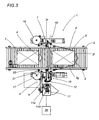
- the pairs of film rolls 5, 6 and 16, 17 are mounted in such a way as to form respective bands of film 9, 9' positioned transversely relative to the uprights 7 and 8 so as to intercept the front of the product stack 3 as it moves forward (see Figure 3).
- the upper band 9' is designed to stabilise the stack 3, whilst the second band 9 usually has the twofold purpose of stabilising the stack 3 and presenting information or codes C relating to the products in the stack 3.
- the units 10 and 10' for sealing and cutting the bands of film 9 and 9' are mounted, relative to the direction of feed A, at the back of the frame 4 and are mobile between:
- sealing and cutting units 10 and 10' are supported by a single mounting unit 22 that projects from the frame 4 and that slides along the crossbeam 4c of the latter to and from the idle and working positions (as indicated by the arrows F in Figures 1 and 2).
- the rolls 5, 6 and 16, 17 are mounted on the uprights 7 and 8 and are equipped with rollers 23 for feeding and tensioning the respective bands of film 9 and 9' being unwound so as to keep the bands of film properly tensioned when they are intercepted by the product stack 3.
- Each of the rolls 5, 6 and 16, 17 also has a carriage 24 coupled to a power driven worm screw shaft 25 that enables adjustment in both directions along the respective upright 7 and 8 (see arrows F2): this permits adjustment of the position of the bands 9, 9' on the stack 3 according to the height of the stack.
- the banding machine 1 also comprises a unit 11, mounted in the vicinity of a section of the path P (shown in Figure 3) along which one of the two bands of film - the one labelled 9 - is unwound and designed to apply at least one distinctive code C to at least one part of the band 9 itself.
- the code C may be any type of label or similar device including any combination of alphanumeric strings, graphics, symbols or logos or any other alternative reference systems such as bar codes.
- the unit 11 may be mounted in the vicinity of one of the film rolls 5 and 6 (in this case it is the lower pair and the roll is the one labelled 6).
- the unit 11 is equipped with a plurality of rollers 12 forming the unwinding path P and defining at least one straight section of film facing the unit 11: in this way, the codes C can be applied to the part of the band 9.
- the unit 11 may be mounted at the upper pair of rollers 16 and 17 so as to apply the codes C to the respective upper band 9' without thereby limiting the scope of the inventive concept.
- the unit 11 is mounted outside the frame 4, on one side of the frame 4.
- the pairs of rolls 5, 6 and 16, 17 can be adjusted in height in both directions and, for this purpose, the unit 11 is equipped with vertical drive means 13 allowing the band 9 and the code C application unit 11 to assume predetermined positions relative to each other.
- the drive means 13 may synchronise the unit 11 with the lower pair of rolls 5 and 6.
- the drive means 13 may, purely by way of example, comprise a beam mounting unit 14 for the unit 11, coupled with a worm screw shaft 15 that may be power driven or actuated manually by an operator in order to drive the unit 11 up and down in synchrony with the rolls 5 and 6 (see arrows F11 in Figure 1).
- the unit 11 may consist of a customary labelling unit 11e equipped with means 11m, a kind of application pad, designed to apply at least one label C to the band of film 9.
- the labelling unit 11e may apply labels C made of paper or plastic, depending on working requirements.
- the code C application unit 11 may comprise means 11s (illustrated schematically in Figures 4, 5 and 6) for printing the codes C directly on the band of film 9 being unwound.
- the unit 11 is connected to a data processing and transmission system 30 (illustrated as a block in Figure 3) to enable the unit 11 to receive the codes C to be printed on the band 9.
- a data processing and transmission system 30 illustrated as a block in Figure 3
- the codes C to be applied to the band 9 are generated while the band 9 itself is being unwound and printed on predetermined parts of the latter (as shown in Figure 1) calculated in accordance with the size of the stack 3 passing by.
- the band 9 may have three sets of codes C applied to it, positioned on the front 3f, on one side 3g and at the back 3r of the stack 3.
- the codes C are generated or applied to the predetermined part Z' during the step of feeding the stack 3 along the conveyor 2 while the band 9 is being unwound and in such a way that the stack front 3f intercepts the film bands 9 and 9' positioned transversally with respect to the uprights 7 and 8.
- the step of generating and applying the codes C to the band 9 is performed preferably while the band 9 is moving normally, or it may be performed while the band 9 is slowed down slightly or stopped for a short length of time. Alternatively, depending on the type of unit 11 used, the unit 11 may be made to move at the same speed as the band 9 being unwound and to generate and apply the codes as it follows the band 9.
- the codes C on the front 3f of the stack 3, on the other hand, are obtained by a step of generating the codes C prior to the step of feeding the stack 3.
- the step of feeding the stack 3 may be preceded by:
- a machine structured as described above therefore achieves the aforementioned objects by incorporating into the banding machine structure a code application unit in such a way that operations previously carried out at two different operating stations are now carried out at a single operating station.
- This architecture makes it possible to speed up stack processing without affecting normal banding time and with the advantage that the stacks have the codes assigned to them applied at the same time as they are banded.
- the incorporation of the code application unit into the banding machine eliminates the need for a labelling station downstream of the banding machine, thus saving time, space and money.
Landscapes
- Engineering & Computer Science (AREA)
- Mechanical Engineering (AREA)
- Basic Packing Technique (AREA)
- Feeding Of Workpieces (AREA)
- Macromolecular Compounds Obtained By Forming Nitrogen-Containing Linkages In General (AREA)
- Pallets (AREA)
Abstract
Description
- The present invention relates to a machine for banding groups of palletised products, in particular palletised loads consisting of stacked products (such as, for example, but not restricted to, packs of bottles or other containers) to undergo intermediate processes and to be transported from one factory to another or from one processing station to another).
- Machines of this type are used to wrap a band of material around a groups of palletised products stacked to a certain height and relatively light in weight, in such a way as to stabilise the stacks during transportation or normal handling in processing lines. Typically, the palletised load consists of bottle crates placed side by side and stacked in two or more layers.
- To stabilise a load of this type, the banding machine wraps a first band of plastic film at a certain height in order to hold the stack together at the most unstable part of it (usually the top of the stack) which would be the first to topple during transportation.
- Prior art machines that perform banding operations of this type comprise a portal frame whose uprights mount a pair of film rolls at a predetermined height. The film is unwound by suitable rollers in such a way that it is positioned transversely between the uprights to intercept the palletised load as the pallet moves under the portal frame on a conveyor.
- The forward motion of the pallet, after its front end has come into contact with the band of film, causes the rolls to unwind so as to wrap the band around the sides of the products stacked on the pallet. As soon as the pallet has moved past the portal frame, it is stopped and a unit comprising a sealer and a cutter, mounted behind the uprights, runs along the back of the palletised load on suitable supports in a direction parallel to the rear face of the load in such a way that the band of film is wrapped right around the load.
- In other words, the film forms a loop around the upper section of the palletised product load and, since the film used is usually stretch film, also has a tightening effect which holds the load together.
- At this point, the section of the band at the back of the palletised load is sealed and, as soon as this has been done, the cutter cuts the band half way between the two sealed ends: that means the looped band wrapped around the palletised load is closed, sealed and cut off, while the seal keeps the two rolls joined to each other by the remaining film positioned transversely between the two uprights and ready to intercept the next palletised load moving forward on the conveyor, thus ensuring that the process is not interrupted.
- An increasingly frequent requirement is for banding machines to apply to the palletised load a second band of film, lower down than the first and bearing a distinguishing mark, such as, for example, a label identifying the products transported, their factory of origin, or other information.
- To make applications of this type possible, the following have been added to banding machines:
- a pair of rolls mounted on the uprights of the portal frame and designed to wrap a second band of plastic film, to which labels can be applied, at a fixed height relative to the uprights themselves; and
- a second sealer and cutter assembly similar to the first assembly, and independent of it, mounted close to the base of the portal frame and mobile in synchrony with the first assembly by means of two additional arms, designed to seal and cut the second band in the same way as the first.
- This type of solution consists basically of a machine already well known in the trade used to apply a single band, with the simple addition of another pair of film rolls and a second, fixed, independent unit but without adapting its constructional philosophy to suit the new requirement.
- This type of structure has several disadvantages which have been overcome in a new solution proposed by the same Applicant as the present (see Italian patent application BO2002 A000232), in which the two sealing and cutting units are supported by a single mounting unit that projects from the portal frame and that slides along the frame crossbeam to and from the idle and working positions of the units: this solution has made the sealing and cutting units extremely, practical and adaptable to any type of production line in which the portal frame is used.
- This improvement has led to a widespread and increased use of labels applied to the plastic bands and bearing information such as product type, destination, origin, quantity, weight, etc.
- The labels, usually placed on three sides of the palletised load, are applied to the plastic band at a station located downstream of the banding machine and equipped with independent label application means.
- This type of configuration, however, tends to slow down the flow of the pallets that have already been banded to enable the labels to be applied and requires an independent, dedicated labelling station which increases the overall dimensions of the production line.
- The present invention has for an object to overcome the above mentioned disadvantages by providing a machine for banding palletised products that has a very compact structure, and is equipped with units for sealing and cutting the plastic band and for applying alphanumeric characters, all mounted in a single station that is quick and easy to adjust and operates in highly synchronised fashion.
- According to the invention, this object is achieved by a machine for banding individual, grouped or palletised products and comprising at least: a conveyor, extending in a direction of feed, for transporting the products; a frame mounted over the conveyor and equipped with at least two rolls of film mounted on the frame uprights in such a way as to form a band of film positioned transversely relative to the uprights so as to intercept the front of the products as they move forward; at least one unit for sealing and cutting the film, supported by the frame and mobile between an idle position, where the unit is close to the uprights, and a working position, where the unit is away from the uprights so that it intercepts, seals and cuts the portion of film band wrapped around the products; the machine further comprises at least one unit located in the vicinity of a section of the film band unwinding path and designed to apply at least one distinctive code to at least one part of the film band.
- The technical characteristics of the invention, with reference to the above objects, are clearly described in the claims below and its advantages are apparent from the detailed description which follows, with reference to the accompanying drawings which illustrate a preferred embodiment of the invention provided merely by way of example without restricting the scope of the inventive concept, and in which:
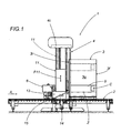
- Figure 1 is a side view, with some parts cut away to better illustrate others, of a machine according to the present invention for banding groups of palletised products;
- Figure 2 is a front view of the banding machine of Figure 1;
- Figure 3 is a top plan view of the banding machine illustrated in the figures listed above;
- Figures 4 to 6 are schematic top plan views illustrating a series of steps in the application of codes to a band placed round the groups of products in a machine according to the present invention.
- With reference to the accompanying drawings, in particular Figures 1 to 3, the machine according to the invention, denoted in its entirety by the
numeral 1, is used for banding, individual, grouped or palletised products. - More specifically, the machine is used, for example, for
palletised stacks 3 of products which have undergone intermediate processes and have to be transported from one factory to another or from one processing station to another. - For example, and without restricting the scope of the invention, the machine is used for banding palletised loads which consist of bottle crates placed side by side and stacked in two or more layers and which necessitate a band of film to stabilise them at the top, and another band of film bearing a series of identification codes at the bottom.
- The
machine 1 comprises aconveyor 2, aframe 4, here in the form of a portal, and a pair of sealing andcutting units 10 and 10'. Obviously, the fact that it comprises two sealing andcutting units 10 and 10' is a non-restrictive example of the solution according to the invention. - More specifically, the
conveyor 2 may consist of a roller conveyor or a conveyor belt extending in a direction of feed A and used to carry the pallets, each supporting astack 3 of the aforementioned products. - The
frame 4 is mounted over theconveyor 2 and is equipped, in this non-restrictive embodiment, with twopairs uprights frame 4. - The pairs of
film rolls film 9, 9' positioned transversely relative to theuprights product stack 3 as it moves forward (see Figure 3). - The upper band 9' is designed to stabilise the
stack 3, whilst thesecond band 9 usually has the twofold purpose of stabilising thestack 3 and presenting information or codes C relating to the products in thestack 3. - The
units 10 and 10' for sealing and cutting the bands offilm 9 and 9' are mounted, relative to the direction of feed A, at the back of theframe 4 and are mobile between: - an idle position, where the
units 10 and 10' are close to theuprights 7 and 8 (as shown in Figure 3); and - a working position, where the
units 10 and 10' are away from theuprights film bands 9 and 9' wrapped around the product stack 3 (as shown in Figure 2), leaving other portions of thebands 9 and 9' positioned transversely between theuprights next stack 3. - Still with reference to Figure 2, the sealing and
cutting units 10 and 10' are supported by asingle mounting unit 22 that projects from theframe 4 and that slides along thecrossbeam 4c of the latter to and from the idle and working positions (as indicated by the arrows F in Figures 1 and 2). - This structure is exhaustively described in Italian patent application BO2002 A000232 by the same Applicant as the present and will not therefore be described in further detail herein.
- The
rolls uprights rollers 23 for feeding and tensioning the respective bands offilm 9 and 9' being unwound so as to keep the bands of film properly tensioned when they are intercepted by theproduct stack 3. - Each of the
rolls carriage 24 coupled to a power drivenworm screw shaft 25 that enables adjustment in both directions along the respective upright 7 and 8 (see arrows F2): this permits adjustment of the position of thebands 9, 9' on thestack 3 according to the height of the stack. - The
banding machine 1 also comprises aunit 11, mounted in the vicinity of a section of the path P (shown in Figure 3) along which one of the two bands of film - the one labelled 9 - is unwound and designed to apply at least one distinctive code C to at least one part of theband 9 itself. - The code C may be any type of label or similar device including any combination of alphanumeric strings, graphics, symbols or logos or any other alternative reference systems such as bar codes.
- The
unit 11 may be mounted in the vicinity of one of the film rolls 5 and 6 (in this case it is the lower pair and the roll is the one labelled 6). Theunit 11 is equipped with a plurality ofrollers 12 forming the unwinding path P and defining at least one straight section of film facing the unit 11: in this way, the codes C can be applied to the part of theband 9. - Similarly (see dashed line in Figure 1), the
unit 11 may be mounted at the upper pair ofrollers - As shown in the accompanying drawings, the
unit 11 is mounted outside theframe 4, on one side of theframe 4. - As mentioned above, the pairs of
rolls unit 11 is equipped with vertical drive means 13 allowing theband 9 and the codeC application unit 11 to assume predetermined positions relative to each other. - Preferably, but without restricting the scope of the invention, the drive means 13 may synchronise the
unit 11 with the lower pair ofrolls - The drive means 13 may, purely by way of example, comprise a
beam mounting unit 14 for theunit 11, coupled with aworm screw shaft 15 that may be power driven or actuated manually by an operator in order to drive theunit 11 up and down in synchrony with therolls 5 and 6 (see arrows F11 in Figure 1). - As regards the type of codes C applicable to the
band 9, theunit 11 may consist of acustomary labelling unit 11e equipped withmeans 11m, a kind of application pad, designed to apply at least one label C to the band offilm 9. - The
labelling unit 11e may apply labels C made of paper or plastic, depending on working requirements. - In an alternative embodiment, the code
C application unit 11 may comprise means 11s (illustrated schematically in Figures 4, 5 and 6) for printing the codes C directly on the band offilm 9 being unwound. - Obviously, the
unit 11 is connected to a data processing and transmission system 30 (illustrated as a block in Figure 3) to enable theunit 11 to receive the codes C to be printed on theband 9. - Similarly, there may be
means 31 for controlling the unwinding of theband 9 and activating theunit 11 in accordance with the parts of theband 9 on which the codes C have to be printed: in practice, the parts where the codes C are to be applied are decided in accordance with the size of theproduct stack 3 and, hence, the length of theband 9 unwound before theunit 11 is activated. - Thus, the codes C to be applied to the
band 9 are generated while theband 9 itself is being unwound and printed on predetermined parts of the latter (as shown in Figure 1) calculated in accordance with the size of thestack 3 passing by. - For easy legibility of the codes C when the
stack 3 is in a warehouse or is being transported from one place to another, theband 9 may have three sets of codes C applied to it, positioned on thefront 3f, on oneside 3g and at theback 3r of thestack 3. - On the
side 3g andback 3r of thestack 3 the codes C are generated or applied to the predetermined part Z' during the step of feeding thestack 3 along theconveyor 2 while theband 9 is being unwound and in such a way that thestack front 3f intercepts thefilm bands 9 and 9' positioned transversally with respect to theuprights band 9 is performed preferably while theband 9 is moving normally, or it may be performed while theband 9 is slowed down slightly or stopped for a short length of time. Alternatively, depending on the type ofunit 11 used, theunit 11 may be made to move at the same speed as theband 9 being unwound and to generate and apply the codes as it follows theband 9. - The codes C on the
front 3f of thestack 3, on the other hand, are obtained by a step of generating the codes C prior to the step of feeding thestack 3. - As illustrated in Figure 4, the step of feeding the
stack 3 may be preceded by: - a step of moving the branch R of the
band 9 positioned transversally with respect to theuprights unit 11 that applies the codes C; - a step of generating at least the codes C on the part Z of the band 9 (see Figure 5);
- a step of further moving the branch R of the
band 9 by an amount sufficient to reposition the branch R between theuprights - These steps of moving the part Z of the
band 9 towards and away from theuprights - A machine structured as described above therefore achieves the aforementioned objects by incorporating into the banding machine structure a code application unit in such a way that operations previously carried out at two different operating stations are now carried out at a single operating station.
- This architecture makes it possible to speed up stack processing without affecting normal banding time and with the advantage that the stacks have the codes assigned to them applied at the same time as they are banded.
- The incorporation of the code application unit into the banding machine eliminates the need for a labelling station downstream of the banding machine, thus saving time, space and money.
- The invention described has evident industrial applications and may be subject to modifications and variations without thereby departing from the scope of the inventive concept. Moreover, all the details of the invention may be substituted by technically equivalent elements.
Claims (16)
- A machine for banding individual, grouped or palletised products, the machine (1) comprising at least:a conveyor (2) extending in a direction of feed (A) and used to transport the products (3);a frame (4) mounted over the conveyor (2) and equipped with at least two rolls (5, 6) of film mounted on the frame uprights (7, 8) in such a way as to form a band of film (9, 9') positioned transversely relative to the uprights (7, 8) and intercepted by the front of the products (3) as they move forward in such a way as to unwind the film from the pair of rolls (5, 6);at least one unit (10) for sealing and cutting the film (9, 9'), supported by the frame (4) and mobile between an idle position, where the unit (10) is close to the uprights (7, 8), and a working position, where the unit (10) is away from the uprights (7, 8) so that it intercepts, seals and cuts the portion of film (9, 9') wrapped around the products (3), the machine being characterised in that it further comprises at least one unit (11) located in the vicinity of a section of the film band (9, 9') unwinding path (P) and designed to apply at least one distinctive code (C) to at least one part of the film band (9, 9').
- The machine according to claim 1, characterised in that the unit (11) is positioned in the vicinity of one of the film rolls (5, 6) and is equipped with a plurality of feed rollers (12) forming the unwinding path (P) and defining at least one straight section of the film (9) facing the unit (11).
- The machine according to claim 1, characterised in that the unit (11) is mounted outside the frame (4), on one side of the frame (4).
- The machine according to claim 1, where the pair of rolls (5, 6) can be adjusted vertically in both directions along the uprights (7, 8) of the frame (4), characterised in that the unit (11) is equipped with vertical drive means (13) allowing the band (9, 9') and the unit (11) to assume predetermined positions relative to each other.
- The machine according to claim 1, where the pair of rolls (5, 6) can be adjusted vertically in both directions along the uprights (7, 8) of the frame (4), characterised in that the unit (11) is equipped with vertical drive means (13) that permit synchronised drive between the band (9, 9') and the unit (11).
- The machine according to claim 1, where there are two pairs of rolls (5, 6; 16, 17) forming respective bands (9, 9') around the palletised product stack (3) and two units (10, 10') for sealing and cutting the respective bands (9, 9'), characterised in that the code (C) application unit (11) is positioned along the path (P) of the band (9) closest to the conveyor (2), that is to say, in the vicinity of a lower roll (6).
- The machine according to claim 1, where there are two pairs of rolls (5, 6; 16, 17) forming respective bands (9, 9') around the palletised product stack (3) and two units (10, 10') for sealing and cutting the respective bands (9, 9'), characterised in that the code (C) application unit (11) is positioned along the path (P) of the band (9') furthest from the conveyor (2), that is to say, in the vicinity of an upper roll (16).
- The machine according to claim 1, characterised in that the unit (11) comprises a labelling unit (11e) and means (11m) for applying at least one label (C) to the band of film (9, 9').
- The machine according to claim 8, characterised in that the unit (11) is equipped with means (11m) for applying at least one label (C) made of paper.
- The machine according to claim 8, characterised in that the unit (11) is equipped with means (11m) for applying at least one label (C) made of plastic.
- The machine according to claim 1, characterised in that the code (C) application unit (11) comprises means (11s) for printing the codes (C) directly on the band of film (9, 9').
- The machine according to claim 1, characterised in that the unit (11) is connected to a data processing and transmission system (30) to enable the unit (11) to receive at least one signal corresponding to at least one distinctive code (C) to be applied to the band (9, 9').
- The machine according to claim 1, characterised in that it comprises means (31) for controlling the unwinding of the band (9, 9') and activating the unit (11) in accordance with the parts (Z, Z') of the band (9, 9') to which the codes (C) have to be applied.
- A method for applying codes (C) to bands of film (9, 9') wrapped around products (3) by a machine (1) as defined in claims 1 to 13, the method comprising at least the step of:feeding the products (3) along the conveyor (2) in such a way that the front (3f) of the products intercepts at least one band of film (9, 9') positioned transversally with respect to the uprights (7, 8), causing the film (9, 9') to be unwound at least from the pair of rolls (5, 6), the method being characterised in that the step of feeding the products (3) and intercepting the film band (9, 9') is preceded by:a step of moving the branch (R) of the band (9, 9') positioned transversally by an amount sufficient to position at least one part (Z) of it at the unit (11) that applies the codes (C);a step of applying at least one distinctive code (C) to the part (Z) of the film (9, 9');a step of further moving the branch (R) of the band (9, 9') by an amount sufficient to reposition the branch (R) between the uprights (7, 8) and with the part (Z) with the code (C) applied to it at a predetermined position.
- The method according to claim 14, characterised in that the steps of moving the part (Z) of the band (9, 9') towards and away from the uprights (7, 8) is accomplished by the joint rotation of the pair of film rolls (5, 6).
- A method for applying codes (C) to bands of film (9, 9') wrapped around products (3) by a machine (1) as defined in claims 1 to 13, the method comprising at least the step of:feeding the products (3) along the conveyor (2) in such a way that the front (3f) of the products intercepts at least one band of film (9, 9') positioned transversally with respect to the uprights (7, 8), causing the film (9, 9') to be unwound at least from the pair of rolls (5, 6), the method being characterised in that the step of unwinding the film band is performed at the same time as a step of applying the code (C) to at least one part (Z) of the film band (9, 9').
Applications Claiming Priority (2)
| Application Number | Priority Date | Filing Date | Title |
|---|---|---|---|
| ITBO20030564 | 2003-09-30 | ||
| IT000564A ITBO20030564A1 (en) | 2003-09-30 | 2003-09-30 | GROUPS MACHINE FOR PALLETIZED PRODUCTS. |
Publications (3)
| Publication Number | Publication Date |
|---|---|
| EP1520784A1 true EP1520784A1 (en) | 2005-04-06 |
| EP1520784B1 EP1520784B1 (en) | 2006-02-22 |
| EP1520784B2 EP1520784B2 (en) | 2010-09-15 |
Family
ID=34308082
Family Applications (1)
| Application Number | Title | Priority Date | Filing Date |
|---|---|---|---|
| EP04425710A Active EP1520784B2 (en) | 2003-09-30 | 2004-09-24 | Machine for banding groups of palletised products. |
Country Status (5)
| Country | Link |
|---|---|
| EP (1) | EP1520784B2 (en) |
| AT (1) | ATE318235T1 (en) |
| DE (1) | DE602004000419T3 (en) |
| ES (1) | ES2257732T5 (en) |
| IT (1) | ITBO20030564A1 (en) |
Cited By (1)
| Publication number | Priority date | Publication date | Assignee | Title |
|---|---|---|---|---|
| EP2199215A2 (en) | 2008-12-09 | 2010-06-23 | Tmi Tecnicas Mecanicas Ilerdenses, S.L. | Stretch wrapping machine and method for stretch wrapping |
Families Citing this family (4)
| Publication number | Priority date | Publication date | Assignee | Title |
|---|---|---|---|---|
| CN103507984B (en) * | 2012-06-26 | 2015-03-11 | 四川制药制剂有限公司 | Device capable of packing drugs automatically |
| DE102012112680B4 (en) * | 2012-12-19 | 2016-09-22 | Gerhard Schwucht | Method and device for strapping a packaged goods with labeling |
| DE102017116458B3 (en) | 2017-07-21 | 2018-08-30 | Valerio Schwucht | Apparatus and method for packaging stacked elongate articles and use of such apparatus |
| WO2024059463A1 (en) * | 2022-09-14 | 2024-03-21 | Signode Industrial Group Llc | System and method for forming a sleeve of paper wrapping material around a load |
Citations (2)
| Publication number | Priority date | Publication date | Assignee | Title |
|---|---|---|---|---|
| US4413463A (en) * | 1980-10-23 | 1983-11-08 | Lantech, Inc. | Roller stretch pass through stretching apparatus and process |
| US6474051B1 (en) * | 1999-02-19 | 2002-11-05 | Msk-Verpackungs-Systeme Gesellschaft Mit Beschrankter Haftung | Apparatus for wrapping a stacked-goods unit with a shrink-foil wrap |
Family Cites Families (4)
| Publication number | Priority date | Publication date | Assignee | Title |
|---|---|---|---|---|
| US3273307A (en) † | 1964-08-03 | 1966-09-20 | Keyes Fibre Co | Wrapping machine |
| US4423584A (en) † | 1981-02-13 | 1984-01-03 | Elsner Engineering Works, Inc. | Roll-wrapping apparatus with label inserter and method |
| US4475651A (en) † | 1981-11-05 | 1984-10-09 | Elsner Engineering Works, Inc. | Roll-wrapping apparatus, method and intermediate product |
| SE468711B (en) † | 1987-01-02 | 1993-03-08 | Andersson Claes Goeran | PACKAGING, INCLUDING A BANDERROLL-LIKE PACKAGING COVER, PURSUANT TO A PROCEDURE AND DEVICE FOR PREPARING A GOOD PACKAGING |
-
2003
- 2003-09-30 IT IT000564A patent/ITBO20030564A1/en unknown
-
2004
- 2004-09-24 EP EP04425710A patent/EP1520784B2/en active Active
- 2004-09-24 DE DE602004000419T patent/DE602004000419T3/en active Active
- 2004-09-24 AT AT04425710T patent/ATE318235T1/en not_active IP Right Cessation
- 2004-09-24 ES ES04425710T patent/ES2257732T5/en active Active
Patent Citations (2)
| Publication number | Priority date | Publication date | Assignee | Title |
|---|---|---|---|---|
| US4413463A (en) * | 1980-10-23 | 1983-11-08 | Lantech, Inc. | Roller stretch pass through stretching apparatus and process |
| US6474051B1 (en) * | 1999-02-19 | 2002-11-05 | Msk-Verpackungs-Systeme Gesellschaft Mit Beschrankter Haftung | Apparatus for wrapping a stacked-goods unit with a shrink-foil wrap |
Cited By (2)
| Publication number | Priority date | Publication date | Assignee | Title |
|---|---|---|---|---|
| EP2199215A2 (en) | 2008-12-09 | 2010-06-23 | Tmi Tecnicas Mecanicas Ilerdenses, S.L. | Stretch wrapping machine and method for stretch wrapping |
| ES2361985A1 (en) * | 2008-12-09 | 2011-06-27 | Tmi Tecnicas Mecanicas Ilerdenses, S.L. | Stretch wrapping machine and method for stretch wrapping |
Also Published As
| Publication number | Publication date |
|---|---|
| ES2257732T5 (en) | 2011-02-24 |
| ES2257732T3 (en) | 2006-08-01 |
| ITBO20030564A1 (en) | 2005-04-01 |
| DE602004000419D1 (en) | 2006-04-27 |
| DE602004000419T3 (en) | 2011-05-05 |
| ATE318235T1 (en) | 2006-03-15 |
| DE602004000419T2 (en) | 2006-08-31 |
| EP1520784B2 (en) | 2010-09-15 |
| EP1520784B1 (en) | 2006-02-22 |
Similar Documents
| Publication | Publication Date | Title |
|---|---|---|
| US20050223683A1 (en) | Apparatus for banding groups of palletised products | |
| US20060096244A1 (en) | Machine for banding groups of palletized products | |
| US8763349B2 (en) | Method and device for producing bundle packages and bundle package | |
| US4050220A (en) | Spiral bundler | |
| US4712354A (en) | Dual rotating stretch wrapping apparatus and process | |
| FI76979C (en) | FOERFARANDE OCH ANORDNING FOER PAKETERING AV FOERETRAEDESVIS REKTANGULAERA FOEREMAOL MED BANFORMIGT OMSLAGSMATERIAL. | |
| EP1707489B1 (en) | Packaging machine and method | |
| US20140075885A1 (en) | Method and device for making packs | |
| US6880316B2 (en) | Method and apparatus for wrapping a top and bottom of a load | |
| EP2450284A1 (en) | Taping machine | |
| EP1520784B1 (en) | Machine for banding groups of palletised products. | |
| AU2004201754B2 (en) | Bundling assembly for strapping machine | |
| EP0623513A2 (en) | Packaging machine with controllable length conveyor | |
| HU224172B1 (en) | Equipment for packing with shrink-wrap for goods in rope | |
| US20110030890A1 (en) | Labelling machine | |
| US4770289A (en) | Clamp bar for fixedly clamping a web against an article | |
| EP1582462B1 (en) | Product banding apparatus | |
| AU2002326212B2 (en) | Method and device for strapping one or more packets with a band with label means | |
| CA1081110A (en) | Reverse wrapper and process | |
| US4979348A (en) | Sealing film applying machine, adapted for packaging parcels, books, signatures and brochures, even individually, by means of a wrapping web | |
| US20030106289A1 (en) | Film feeding device for a single layer color film packaging machine | |
| CN211417871U (en) | Packing carton labeller that four sides were pasted mark | |
| JPH10329810A (en) | Belt type vacuum packaging machine | |
| WO1992009484A1 (en) | Device for applying a label around a barrel | |
| JPH08119212A (en) | Packaging apparatus |
Legal Events
| Date | Code | Title | Description |
|---|---|---|---|
| PUAI | Public reference made under article 153(3) epc to a published international application that has entered the european phase |
Free format text: ORIGINAL CODE: 0009012 |
|
| AK | Designated contracting states |
Kind code of ref document: A1 Designated state(s): AT BE BG CH CY CZ DE DK EE ES FI FR GB GR HU IE IT LI LU MC NL PL PT RO SE SI SK TR |
|
| AX | Request for extension of the european patent |
Extension state: AL HR LT LV MK |
|
| 17P | Request for examination filed |
Effective date: 20050411 |
|
| GRAP | Despatch of communication of intention to grant a patent |
Free format text: ORIGINAL CODE: EPIDOSNIGR1 |
|
| GRAS | Grant fee paid |
Free format text: ORIGINAL CODE: EPIDOSNIGR3 |
|
| AKX | Designation fees paid |
Designated state(s): AT BE BG CH CY CZ DE DK EE ES FI FR GB GR HU IE IT LI LU MC NL PL PT RO SE SI SK TR |
|
| GRAA | (expected) grant |
Free format text: ORIGINAL CODE: 0009210 |
|
| AK | Designated contracting states |
Kind code of ref document: B1 Designated state(s): AT BE BG CH CY CZ DE DK EE ES FI FR GB GR HU IE IT LI LU MC NL PL PT RO SE SI SK TR |
|
| PG25 | Lapsed in a contracting state [announced via postgrant information from national office to epo] |
Ref country code: SK Free format text: LAPSE BECAUSE OF FAILURE TO SUBMIT A TRANSLATION OF THE DESCRIPTION OR TO PAY THE FEE WITHIN THE PRESCRIBED TIME-LIMIT Effective date: 20060222 Ref country code: FI Free format text: LAPSE BECAUSE OF FAILURE TO SUBMIT A TRANSLATION OF THE DESCRIPTION OR TO PAY THE FEE WITHIN THE PRESCRIBED TIME-LIMIT Effective date: 20060222 Ref country code: AT Free format text: LAPSE BECAUSE OF FAILURE TO SUBMIT A TRANSLATION OF THE DESCRIPTION OR TO PAY THE FEE WITHIN THE PRESCRIBED TIME-LIMIT Effective date: 20060222 Ref country code: RO Free format text: LAPSE BECAUSE OF FAILURE TO SUBMIT A TRANSLATION OF THE DESCRIPTION OR TO PAY THE FEE WITHIN THE PRESCRIBED TIME-LIMIT Effective date: 20060222 Ref country code: NL Free format text: LAPSE BECAUSE OF FAILURE TO SUBMIT A TRANSLATION OF THE DESCRIPTION OR TO PAY THE FEE WITHIN THE PRESCRIBED TIME-LIMIT Effective date: 20060222 Ref country code: SI Free format text: LAPSE BECAUSE OF FAILURE TO SUBMIT A TRANSLATION OF THE DESCRIPTION OR TO PAY THE FEE WITHIN THE PRESCRIBED TIME-LIMIT Effective date: 20060222 Ref country code: PL Free format text: LAPSE BECAUSE OF FAILURE TO SUBMIT A TRANSLATION OF THE DESCRIPTION OR TO PAY THE FEE WITHIN THE PRESCRIBED TIME-LIMIT Effective date: 20060222 |
|
| REG | Reference to a national code |
Ref country code: GB Ref legal event code: FG4D |
|
| REG | Reference to a national code |
Ref country code: CH Ref legal event code: EP |
|
| REG | Reference to a national code |
Ref country code: CH Ref legal event code: NV Representative=s name: ISLER & PEDRAZZINI AG |
|
| REG | Reference to a national code |
Ref country code: IE Ref legal event code: FG4D |
|
| REF | Corresponds to: |
Ref document number: 602004000419 Country of ref document: DE Date of ref document: 20060427 Kind code of ref document: P |
|
| PG25 | Lapsed in a contracting state [announced via postgrant information from national office to epo] |
Ref country code: SE Free format text: LAPSE BECAUSE OF FAILURE TO SUBMIT A TRANSLATION OF THE DESCRIPTION OR TO PAY THE FEE WITHIN THE PRESCRIBED TIME-LIMIT Effective date: 20060522 Ref country code: BG Free format text: LAPSE BECAUSE OF FAILURE TO SUBMIT A TRANSLATION OF THE DESCRIPTION OR TO PAY THE FEE WITHIN THE PRESCRIBED TIME-LIMIT Effective date: 20060522 Ref country code: DK Free format text: LAPSE BECAUSE OF FAILURE TO SUBMIT A TRANSLATION OF THE DESCRIPTION OR TO PAY THE FEE WITHIN THE PRESCRIBED TIME-LIMIT Effective date: 20060522 |
|
| PG25 | Lapsed in a contracting state [announced via postgrant information from national office to epo] |
Ref country code: PT Free format text: LAPSE BECAUSE OF FAILURE TO SUBMIT A TRANSLATION OF THE DESCRIPTION OR TO PAY THE FEE WITHIN THE PRESCRIBED TIME-LIMIT Effective date: 20060724 |
|
| NLV1 | Nl: lapsed or annulled due to failure to fulfill the requirements of art. 29p and 29m of the patents act | ||
| REG | Reference to a national code |
Ref country code: ES Ref legal event code: FG2A Ref document number: 2257732 Country of ref document: ES Kind code of ref document: T3 |
|
| PG25 | Lapsed in a contracting state [announced via postgrant information from national office to epo] |
Ref country code: IE Free format text: LAPSE BECAUSE OF NON-PAYMENT OF DUE FEES Effective date: 20060925 |
|
| PG25 | Lapsed in a contracting state [announced via postgrant information from national office to epo] |
Ref country code: MC Free format text: LAPSE BECAUSE OF NON-PAYMENT OF DUE FEES Effective date: 20060930 |
|
| ET | Fr: translation filed | ||
| PLBI | Opposition filed |
Free format text: ORIGINAL CODE: 0009260 |
|
| PLAX | Notice of opposition and request to file observation + time limit sent |
Free format text: ORIGINAL CODE: EPIDOSNOBS2 |
|
| 26 | Opposition filed |
Opponent name: EURAPACK GMBH Effective date: 20061120 |
|
| PLAF | Information modified related to communication of a notice of opposition and request to file observations + time limit |
Free format text: ORIGINAL CODE: EPIDOSCOBS2 |
|
| PLBB | Reply of patent proprietor to notice(s) of opposition received |
Free format text: ORIGINAL CODE: EPIDOSNOBS3 |
|
| REG | Reference to a national code |
Ref country code: CH Ref legal event code: PCAR Free format text: ISLER & PEDRAZZINI AG;POSTFACH 1772;8027 ZUERICH (CH) |
|
| PLAY | Examination report in opposition despatched + time limit |
Free format text: ORIGINAL CODE: EPIDOSNORE2 |
|
| PLAH | Information related to despatch of examination report in opposition + time limit modified |
Free format text: ORIGINAL CODE: EPIDOSCORE2 |
|
| PG25 | Lapsed in a contracting state [announced via postgrant information from national office to epo] |
Ref country code: CZ Free format text: LAPSE BECAUSE OF FAILURE TO SUBMIT A TRANSLATION OF THE DESCRIPTION OR TO PAY THE FEE WITHIN THE PRESCRIBED TIME-LIMIT Effective date: 20060222 Ref country code: GR Free format text: LAPSE BECAUSE OF FAILURE TO SUBMIT A TRANSLATION OF THE DESCRIPTION OR TO PAY THE FEE WITHIN THE PRESCRIBED TIME-LIMIT Effective date: 20060523 |
|
| PG25 | Lapsed in a contracting state [announced via postgrant information from national office to epo] |
Ref country code: EE Free format text: LAPSE BECAUSE OF FAILURE TO SUBMIT A TRANSLATION OF THE DESCRIPTION OR TO PAY THE FEE WITHIN THE PRESCRIBED TIME-LIMIT Effective date: 20060222 |
|
| PLAH | Information related to despatch of examination report in opposition + time limit modified |
Free format text: ORIGINAL CODE: EPIDOSCORE2 |
|
| PG25 | Lapsed in a contracting state [announced via postgrant information from national office to epo] |
Ref country code: HU Free format text: LAPSE BECAUSE OF FAILURE TO SUBMIT A TRANSLATION OF THE DESCRIPTION OR TO PAY THE FEE WITHIN THE PRESCRIBED TIME-LIMIT Effective date: 20060823 Ref country code: TR Free format text: LAPSE BECAUSE OF FAILURE TO SUBMIT A TRANSLATION OF THE DESCRIPTION OR TO PAY THE FEE WITHIN THE PRESCRIBED TIME-LIMIT Effective date: 20060222 Ref country code: LU Free format text: LAPSE BECAUSE OF NON-PAYMENT OF DUE FEES Effective date: 20060924 |
|
| PLAH | Information related to despatch of examination report in opposition + time limit modified |
Free format text: ORIGINAL CODE: EPIDOSCORE2 |
|
| PG25 | Lapsed in a contracting state [announced via postgrant information from national office to epo] |
Ref country code: CY Free format text: LAPSE BECAUSE OF FAILURE TO SUBMIT A TRANSLATION OF THE DESCRIPTION OR TO PAY THE FEE WITHIN THE PRESCRIBED TIME-LIMIT Effective date: 20060222 |
|
| PLAH | Information related to despatch of examination report in opposition + time limit modified |
Free format text: ORIGINAL CODE: EPIDOSCORE2 |
|
| PLAH | Information related to despatch of examination report in opposition + time limit modified |
Free format text: ORIGINAL CODE: EPIDOSCORE2 |
|
| PLAH | Information related to despatch of examination report in opposition + time limit modified |
Free format text: ORIGINAL CODE: EPIDOSCORE2 |
|
| PLBC | Reply to examination report in opposition received |
Free format text: ORIGINAL CODE: EPIDOSNORE3 |
|
| PLBP | Opposition withdrawn |
Free format text: ORIGINAL CODE: 0009264 |
|
| PUAH | Patent maintained in amended form |
Free format text: ORIGINAL CODE: 0009272 |
|
| STAA | Information on the status of an ep patent application or granted ep patent |
Free format text: STATUS: PATENT MAINTAINED AS AMENDED |
|
| 27A | Patent maintained in amended form |
Effective date: 20100915 |
|
| AK | Designated contracting states |
Kind code of ref document: B2 Designated state(s): AT BE BG CH CY CZ DE DK EE ES FI FR GB GR HU IE IT LI LU MC NL PL PT RO SE SI SK TR |
|
| REG | Reference to a national code |
Ref country code: CH Ref legal event code: AEN Free format text: MANTENIMENTO DEL BREVETTO IN FORMA MODIFICATA |
|
| REG | Reference to a national code |
Ref country code: ES Ref legal event code: DC2A Effective date: 20110214 |
|
| PGFP | Annual fee paid to national office [announced via postgrant information from national office to epo] |
Ref country code: BE Payment date: 20100929 Year of fee payment: 7 |
|
| PG25 | Lapsed in a contracting state [announced via postgrant information from national office to epo] |
Ref country code: BE Free format text: LAPSE BECAUSE OF NON-PAYMENT OF DUE FEES Effective date: 20110930 |
|
| REG | Reference to a national code |
Ref country code: FR Ref legal event code: PLFP Year of fee payment: 13 |
|
| REG | Reference to a national code |
Ref country code: FR Ref legal event code: PLFP Year of fee payment: 14 |
|
| REG | Reference to a national code |
Ref country code: FR Ref legal event code: PLFP Year of fee payment: 15 |
|
| PGFP | Annual fee paid to national office [announced via postgrant information from national office to epo] |
Ref country code: GB Payment date: 20220922 Year of fee payment: 19 Ref country code: DE Payment date: 20220928 Year of fee payment: 19 |
|
| PGFP | Annual fee paid to national office [announced via postgrant information from national office to epo] |
Ref country code: FR Payment date: 20220924 Year of fee payment: 19 |
|
| PGFP | Annual fee paid to national office [announced via postgrant information from national office to epo] |
Ref country code: IT Payment date: 20220930 Year of fee payment: 19 Ref country code: ES Payment date: 20221003 Year of fee payment: 19 |
|
| PGFP | Annual fee paid to national office [announced via postgrant information from national office to epo] |
Ref country code: CH Payment date: 20220928 Year of fee payment: 19 |
|
| P01 | Opt-out of the competence of the unified patent court (upc) registered |
Effective date: 20230515 |
|
| REG | Reference to a national code |
Ref country code: DE Ref legal event code: R119 Ref document number: 602004000419 Country of ref document: DE |
|
| REG | Reference to a national code |
Ref country code: CH Ref legal event code: PL |