EP1520750A1 - Vehicle mirror - Google Patents
Vehicle mirror Download PDFInfo
- Publication number
- EP1520750A1 EP1520750A1 EP04077677A EP04077677A EP1520750A1 EP 1520750 A1 EP1520750 A1 EP 1520750A1 EP 04077677 A EP04077677 A EP 04077677A EP 04077677 A EP04077677 A EP 04077677A EP 1520750 A1 EP1520750 A1 EP 1520750A1
- Authority
- EP
- European Patent Office
- Prior art keywords
- vehicle
- foot
- mirror
- foot part
- fixing
- Prior art date
- Legal status (The legal status is an assumption and is not a legal conclusion. Google has not performed a legal analysis and makes no representation as to the accuracy of the status listed.)
- Granted
Links
Images


Classifications
-
- B—PERFORMING OPERATIONS; TRANSPORTING
- B60—VEHICLES IN GENERAL
- B60R—VEHICLES, VEHICLE FITTINGS, OR VEHICLE PARTS, NOT OTHERWISE PROVIDED FOR
- B60R1/00—Optical viewing arrangements; Real-time viewing arrangements for drivers or passengers using optical image capturing systems, e.g. cameras or video systems specially adapted for use in or on vehicles
- B60R1/02—Rear-view mirror arrangements
- B60R1/06—Rear-view mirror arrangements mounted on vehicle exterior
Definitions
- the present invention relates to a vehicle mirror to be fitted on a panel section of a vehicle, comprising a foot, to be fixed to said panel section of said vehicle, a mirror housing with mirror and an arm linking the foot and the mirror housing.
- Such a vehicle mirror is generally known in the art and is intended in particular for subsequent fitting to a vehicle. After all, there are fixings designed by the manufacturer for conventional rear view mirrors. However, it is often necessary to fit further mirrors at a later stage. Examples of these are mirrors fitted to the rear of a vehicle to be able to observe the region immediately behind the vehicle, blind spot mirrors and other mirrors that make the region around the vehicle visible to the driver. As a result of the change of government regulations, subsequent fitting of such mirrors is very common.
- a foot that consists of a top part to be fixed to a plate is disclosed in GB 1 403 588. Turning with respect to one another is not possible here. This can be achieved only by turning the arm relative to the casting.
- JP 08268163 discloses a mirror where the foot is fixed to the bodywork via an adhesive material. Turning is no longer possible after fixing.
- the aim of the present invention is to avoid these disadvantages and appreciably to simplify the fixing of a vehicle mirror to be fitted on a vehicle.
- said foot comprises two foot parts, a first part joined to said arm and a second part, provided with fixing means for fixing to said panel section, wherein said first and second foot part are provided with interacting engagement means, as a result of which said first and second part can be secured in different angular positions with respect to one another.
- the second foot part is first fixed to the vehicle in some way or other.
- This fixing is a definitive fixing.
- the first foot part can be fastened to the second foot part in various angular positions with respect thereto. That is to say if it is found when combining the foot parts that the mirror does not display the correct region it is then not necessary to undo the fixing to the vehicle but only the fixing between the foot parts.
- These foot parts are preferably made circular. More particularly, the second foot part, which is fixed to the vehicle, has a relatively large diameter so that a large supporting surface on the vehicle is obtained. Fixing to the vehicle can take place in any way known in the art. According to an advantageous embodiment, however, use is made of an adhesive layer, which moreover has some give.
- Such an adhesive layer can, for example, be realised by double-sided adhesive tape. This adheres on one side to the second foot part and before use the protective strip can be removed from the adhesive tape and simple fixing to, for example, a vehicle window or panel can thus be achieved. As indicated above, this fixing is one-off, so that the problem of adhesion decreasing on repeated fixing does not arise.
- first and second foot part are secured in a number of discrete positions with respect to one another.
- a particularly stable and simple fixing of the first and second foot part can be obtained by this means.
- Such discrete positions can be obtained by means of a ridge/groove mechanism or a mechanism with serrations engaging in one another.
- these serrations are as far as possible at the periphery of both the first and the second foot part. If the serrations arranged on, preferably, the first foot part have resilient lips, slight deflections can be absorbed without any problem.
- the distance between opposing serrations on the resilient lips is preferably 5 - 15 cm.
- Fig. 1 the vehicle mirror according to the present invention is indicated in its entirety by 1.
- This mirror is fitted on the rear of a vehicle 2 and more particularly on the rear window of a door thereof.
- the mirror 1 consists of a mirror housing 6 in which a mirror 8 is accommodated.
- This mirror can be any mirror known in the state of the art (flat, convex, and the like).
- Mirror housing 6 is joined to mirror arm 5 via a pivot joint that is not shown in detail.
- Mirror arm 5 is joined to foot 4, again in a pivotable manner.
- foot 4 consists of a first foot part 10 and a second foot part 11. Arm 5 is joined to the first foot part 10.
- an opening 7 has been made in arm 5 for inserting a bolt 9 therein.
- the second foot part 11 which is preferably somewhat flexible, is provided with a bush with corresponding screw thread, so that bolt 9 is able to join the first foot part 10 to the second foot part 11.
- the head of bolt 9 is, of course, below the underside of arm 5, so that the pivoting movement thereof is not impeded by bolt 9.
- first, preferably rigid, foot part 10 is provided with a number of peripheral lips 14. It can be seen from Fig. 3 that each lip 14 is provided with serrations 18. Both the first and second foot part are circular and the distance between the opposing serrations 15 is indicated by a in Fig. 3 and is approximately 7 cm.
- the second foot part 11 is provided with a raised rim 17, within which serrations 13 are arranged (Fig. 2).
- the second foot part 11 is provided with a ring of double-sided adhesive tape 16, provided with a covering strip that is not shown in more detail (Fig. 3).
- the mirror described above is fitted as follows. Before fitting the first and second foot part are separated. The strip is removed from the adhesive tape 16 on the second foot part 11. The relevant surface of the vehicle where the mirror has to be fitted is cleaned and the second foot part is then stuck to the part of the vehicle in the desired position. The "rotational setting" of this position is of minor importance. The first foot part 10 together with the other part of the mirror is then positioned. During this positioning the ends of the resilient lips 14 drop inside the raised rim 17. By tightening bolt 9 in bush 12, securing of the two foot parts 10 and 11 such that they cannot be turned can be obtained. If it is subsequently found that the mirror cannot be adjusted properly, bolt 9 can then easily be undone and a better mutual positioning between the foot parts 10 and 11 can be provided.
Landscapes
- Engineering & Computer Science (AREA)
- Multimedia (AREA)
- Mechanical Engineering (AREA)
- Rear-View Mirror Devices That Are Mounted On The Exterior Of The Vehicle (AREA)
- Laminated Bodies (AREA)
- Mirrors, Picture Frames, Photograph Stands, And Related Fastening Devices (AREA)
Abstract
Description
- The present invention relates to a vehicle mirror to be fitted on a panel section of a vehicle, comprising a foot, to be fixed to said panel section of said vehicle, a mirror housing with mirror and an arm linking the foot and the mirror housing.
- Such a vehicle mirror is generally known in the art and is intended in particular for subsequent fitting to a vehicle. After all, there are fixings designed by the manufacturer for conventional rear view mirrors. However, it is often necessary to fit further mirrors at a later stage. Examples of these are mirrors fitted to the rear of a vehicle to be able to observe the region immediately behind the vehicle, blind spot mirrors and other mirrors that make the region around the vehicle visible to the driver. As a result of the change of government regulations, subsequent fitting of such mirrors is very common.
- When fitting such mirrors it is generally not desired that holes are made in the vehicle. Moreover, in some situations this is not possible (windows). On the other hand it is desirable to provide a firm, stable fixing, where simple assembly is moreover possible. In the art there is the problem that once a mirror has been fixed to a part of the vehicle it can be found that this fixing is incorrect when adjusting the mirror. In practice, the fixing is then undone and correct fixing of the foot is then realised in another position. As a result there is damage to the vehicle and the effectiveness of the fixing decreases.
- A foot that consists of a top part to be fixed to a plate is disclosed in
GB 1 403 588. Turning with respect to one another is not possible here. This can be achieved only by turning the arm relative to the casting. - JP 08268163 discloses a mirror where the foot is fixed to the bodywork via an adhesive material. Turning is no longer possible after fixing.
- The aim of the present invention is to avoid these disadvantages and appreciably to simplify the fixing of a vehicle mirror to be fitted on a vehicle.
- This aim is realised with a vehicle mirror as described above in that said foot comprises two foot parts, a first part joined to said arm and a second part, provided with fixing means for fixing to said panel section, wherein said first and second foot part are provided with interacting engagement means, as a result of which said first and second part can be secured in different angular positions with respect to one another.
- According to the present invention the second foot part is first fixed to the vehicle in some way or other. This fixing is a definitive fixing. After all, the first foot part can be fastened to the second foot part in various angular positions with respect thereto. That is to say if it is found when combining the foot parts that the mirror does not display the correct region it is then not necessary to undo the fixing to the vehicle but only the fixing between the foot parts. These foot parts are preferably made circular. More particularly, the second foot part, which is fixed to the vehicle, has a relatively large diameter so that a large supporting surface on the vehicle is obtained. Fixing to the vehicle can take place in any way known in the art. According to an advantageous embodiment, however, use is made of an adhesive layer, which moreover has some give. Such an adhesive layer can, for example, be realised by double-sided adhesive tape. This adheres on one side to the second foot part and before use the protective strip can be removed from the adhesive tape and simple fixing to, for example, a vehicle window or panel can thus be achieved. As indicated above, this fixing is one-off, so that the problem of adhesion decreasing on repeated fixing does not arise.
- Because both the mirror housing and the foot are fitted such that they can be moved with respect to the arm, a certain degree of adjustment is thus possible. Therefore it has proved adequate for the first and second foot part to be secured in a number of discrete positions with respect to one another. A particularly stable and simple fixing of the first and second foot part can be obtained by this means. Such discrete positions can be obtained by means of a ridge/groove mechanism or a mechanism with serrations engaging in one another.
- In order to provide a stable assembly, these serrations are as far as possible at the periphery of both the first and the second foot part. If the serrations arranged on, preferably, the first foot part have resilient lips, slight deflections can be absorbed without any problem.
- The distance between opposing serrations on the resilient lips is preferably 5 - 15 cm.
- The invention will be explained in more detail below with reference to an illustrative embodiment shown in the drawings. In the drawings:
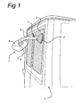
- Fig. 1 shows, diagrammatically, a vehicle mirror according to the invention fitted on the rear of a vehicle;
- Fig. 2 shows the two foot sections in a first perspective view; and
- Fig. 3 shows the two foot sections according to the invention in a second perspective view.
-
- In Fig. 1 the vehicle mirror according to the present invention is indicated in its entirety by 1. This mirror is fitted on the rear of a
vehicle 2 and more particularly on the rear window of a door thereof. Themirror 1 consists of a mirror housing 6 in which amirror 8 is accommodated. This mirror can be any mirror known in the state of the art (flat, convex, and the like). Mirror housing 6 is joined tomirror arm 5 via a pivot joint that is not shown in detail.Mirror arm 5 is joined tofoot 4, again in a pivotable manner. It can be seen from Figs 2 and 3 thatfoot 4 consists of afirst foot part 10 and asecond foot part 11.Arm 5 is joined to thefirst foot part 10. Furthermore, anopening 7 has been made inarm 5 for inserting abolt 9 therein. Thesecond foot part 11, which is preferably somewhat flexible, is provided with a bush with corresponding screw thread, so thatbolt 9 is able to join thefirst foot part 10 to thesecond foot part 11. In the fitted position, the head ofbolt 9 is, of course, below the underside ofarm 5, so that the pivoting movement thereof is not impeded bybolt 9. - It can be seen from Fig. 2 that the first, preferably rigid,
foot part 10 is provided with a number ofperipheral lips 14. It can be seen from Fig. 3 that eachlip 14 is provided withserrations 18. Both the first and second foot part are circular and the distance between theopposing serrations 15 is indicated by a in Fig. 3 and is approximately 7 cm. - The
second foot part 11 is provided with a raisedrim 17, within whichserrations 13 are arranged (Fig. 2). On the rear thesecond foot part 11 is provided with a ring of double-sidedadhesive tape 16, provided with a covering strip that is not shown in more detail (Fig. 3). - The mirror described above is fitted as follows. Before fitting the first and second foot part are separated. The strip is removed from the
adhesive tape 16 on thesecond foot part 11. The relevant surface of the vehicle where the mirror has to be fitted is cleaned and the second foot part is then stuck to the part of the vehicle in the desired position. The "rotational setting" of this position is of minor importance. Thefirst foot part 10 together with the other part of the mirror is then positioned. During this positioning the ends of theresilient lips 14 drop inside the raisedrim 17. By tighteningbolt 9 inbush 12, securing of the twofoot parts bolt 9 can then easily be undone and a better mutual positioning between thefoot parts - Although the invention has been described above with reference to a preferred embodiment, it will be understood that numerous modifications can be made thereto without going beyond the scope of the present application. For instance, it is possible for the foot parts to have a different shape and for the mutual engagement to be implemented in any other manner known per se in the state of the art. These and further modifications fall within the scope of the present application.
Claims (8)
- Vehicle mirror (1) to be fitted on a panel section (3) of a vehicle (2), comprising a foot (4), to be fixed to said panel section of said vehicle, a mirror housing (6) with mirror (8) and an arm (5) linking the foot and the mirror housing, characterised in that said foot comprises two foot parts (10, 11), a first part (10) joined to said arm (5) and a second part (11), provided with fixing means (16) for fixing to said panel section, wherein said first and second foot part are provided with interacting engagement means (13, 15), as a result of which said first and second part can be secured in different angular positions with respect to one another.
- Vehicle mirror according to Claim 1, wherein said positions are discrete positions.
- Vehicle mirror according to one of the preceding claims, wherein said engagement means comprise serrations (13, 18).
- Vehicle mirror according to Claim 3, wherein said serrations are arranged on peripheral lips (14).
- Vehicle mirror according to Claim 4, wherein said peripheral lips are resilient lips.
- Vehicle mirror according to Claim 4 or 5, wherein the effective ends of said lips are a distance (a) of at least 5 cm apart.
- Vehicle mirror according to Claim 6, wherein said second foot part is provided with an adhesive layer (16) with give.
- Vehicle mirror according to Claim 7, wherein said adhesive layer is a double-sided adhesive tape.
Applications Claiming Priority (2)
| Application Number | Priority Date | Filing Date | Title |
|---|---|---|---|
| NL1024410A NL1024410C2 (en) | 2003-09-30 | 2003-09-30 | Vehicle mirror. |
| NL1024410 | 2003-09-30 |
Publications (2)
| Publication Number | Publication Date |
|---|---|
| EP1520750A1 true EP1520750A1 (en) | 2005-04-06 |
| EP1520750B1 EP1520750B1 (en) | 2008-11-12 |
Family
ID=34309612
Family Applications (1)
| Application Number | Title | Priority Date | Filing Date |
|---|---|---|---|
| EP04077677A Revoked EP1520750B1 (en) | 2003-09-30 | 2004-09-28 | Vehicle mirror |
Country Status (6)
| Country | Link |
|---|---|
| EP (1) | EP1520750B1 (en) |
| AT (1) | ATE413985T1 (en) |
| DE (1) | DE602004017686D1 (en) |
| DK (1) | DK1520750T3 (en) |
| ES (1) | ES2316921T3 (en) |
| NL (1) | NL1024410C2 (en) |
Cited By (1)
| Publication number | Priority date | Publication date | Assignee | Title |
|---|---|---|---|---|
| DE102013003586A1 (en) | 2013-03-02 | 2013-09-19 | Daimler Ag | Electrical power supply system for motor car, has conductor path electrically connecting power supply unit with onboard network, and locking element comprising response time shorter than response time of fuse element |
Citations (4)
| Publication number | Priority date | Publication date | Assignee | Title |
|---|---|---|---|---|
| GB1403588A (en) | 1972-02-19 | 1975-08-28 | Tanaka Seisakusho Kk | Rearview mirrors for automobiles |
| JPH08268163A (en) | 1995-03-31 | 1996-10-15 | Yoshitomi Araki | Rear under mirror for automobile |
| JP2000190780A (en) * | 1998-12-24 | 2000-07-11 | Shinji Inoue | Tail mirror |
| JP2002036965A (en) * | 2000-07-22 | 2002-02-06 | Toshiyuki Niki | Plane-or-curved-surface-commonly used adhesive fixture for automobile fixtures |
-
2003
- 2003-09-30 NL NL1024410A patent/NL1024410C2/en not_active IP Right Cessation
-
2004
- 2004-09-28 ES ES04077677T patent/ES2316921T3/en not_active Expired - Lifetime
- 2004-09-28 DK DK04077677T patent/DK1520750T3/en active
- 2004-09-28 AT AT04077677T patent/ATE413985T1/en not_active IP Right Cessation
- 2004-09-28 DE DE602004017686T patent/DE602004017686D1/en not_active Expired - Lifetime
- 2004-09-28 EP EP04077677A patent/EP1520750B1/en not_active Revoked
Patent Citations (4)
| Publication number | Priority date | Publication date | Assignee | Title |
|---|---|---|---|---|
| GB1403588A (en) | 1972-02-19 | 1975-08-28 | Tanaka Seisakusho Kk | Rearview mirrors for automobiles |
| JPH08268163A (en) | 1995-03-31 | 1996-10-15 | Yoshitomi Araki | Rear under mirror for automobile |
| JP2000190780A (en) * | 1998-12-24 | 2000-07-11 | Shinji Inoue | Tail mirror |
| JP2002036965A (en) * | 2000-07-22 | 2002-02-06 | Toshiyuki Niki | Plane-or-curved-surface-commonly used adhesive fixture for automobile fixtures |
Non-Patent Citations (3)
| Title |
|---|
| PATENT ABSTRACTS OF JAPAN vol. 1997, no. 02 28 February 1997 (1997-02-28) * |
| PATENT ABSTRACTS OF JAPAN vol. 2000, no. 10 17 November 2000 (2000-11-17) * |
| PATENT ABSTRACTS OF JAPAN vol. 2002, no. 06 4 June 2002 (2002-06-04) * |
Cited By (1)
| Publication number | Priority date | Publication date | Assignee | Title |
|---|---|---|---|---|
| DE102013003586A1 (en) | 2013-03-02 | 2013-09-19 | Daimler Ag | Electrical power supply system for motor car, has conductor path electrically connecting power supply unit with onboard network, and locking element comprising response time shorter than response time of fuse element |
Also Published As
| Publication number | Publication date |
|---|---|
| ES2316921T3 (en) | 2009-04-16 |
| EP1520750B1 (en) | 2008-11-12 |
| DE602004017686D1 (en) | 2008-12-24 |
| ATE413985T1 (en) | 2008-11-15 |
| DK1520750T3 (en) | 2009-03-09 |
| NL1024410C2 (en) | 2005-03-31 |
Similar Documents
| Publication | Publication Date | Title |
|---|---|---|
| US4268120A (en) | Automobile mirror device | |
| US6079852A (en) | Auxiliary light | |
| US5165081A (en) | Auxiliary clamp-on mirror | |
| US7686374B1 (en) | Vehicle visor assembly | |
| EP1493650A1 (en) | Car roof module | |
| USD483705S1 (en) | Front grille for an automobile | |
| JP2012148757A (en) | Support tool of travel assisting device inside automobile | |
| EP1520750B1 (en) | Vehicle mirror | |
| US4322132A (en) | Composite vent window and rear-view mirror | |
| JP3617596B2 (en) | Room lamp mounting structure | |
| JP3500017B2 (en) | Temporary fastening structure of vehicle window | |
| JP3238915B2 (en) | Equipment mounting structure to bumper | |
| US4176876A (en) | Wind deflector | |
| JPH05330343A (en) | Door trim with service hole cover | |
| KR200213953Y1 (en) | Inside auxiliary mirror of car | |
| JP2000314216A (en) | Downspout support | |
| JPH0242522Y2 (en) | ||
| JP2946709B2 (en) | Automotive side body structure | |
| KR200452660Y1 (en) | Blind Spot Mirror | |
| JP2002120660A (en) | Method of assembling roof lining for vehicle body | |
| JPH0356430Y2 (en) | ||
| JPH07246835A (en) | Glare shielding plate for automobile wind shield | |
| JPS6365528B2 (en) | ||
| JP2024018612A (en) | Side visor mounting structure and side visor | |
| JPH0534453Y2 (en) |
Legal Events
| Date | Code | Title | Description |
|---|---|---|---|
| PUAI | Public reference made under article 153(3) epc to a published international application that has entered the european phase |
Free format text: ORIGINAL CODE: 0009012 |
|
| AK | Designated contracting states |
Kind code of ref document: A1 Designated state(s): AT BE BG CH CY CZ DE DK EE ES FI FR GB GR HU IE IT LI LU MC NL PL PT RO SE SI SK TR |
|
| AX | Request for extension of the european patent |
Extension state: AL HR LT LV MK |
|
| 17P | Request for examination filed |
Effective date: 20050603 |
|
| AKX | Designation fees paid |
Designated state(s): AT BE BG CH CY CZ DE DK EE ES FI FR GB GR HU IE IT LI LU MC NL PL PT RO SE SI SK TR |
|
| GRAP | Despatch of communication of intention to grant a patent |
Free format text: ORIGINAL CODE: EPIDOSNIGR1 |
|
| GRAS | Grant fee paid |
Free format text: ORIGINAL CODE: EPIDOSNIGR3 |
|
| GRAA | (expected) grant |
Free format text: ORIGINAL CODE: 0009210 |
|
| AK | Designated contracting states |
Kind code of ref document: B1 Designated state(s): AT BE BG CH CY CZ DE DK EE ES FI FR GB GR HU IE IT LI LU MC NL PL PT RO SE SI SK TR |
|
| REG | Reference to a national code |
Ref country code: GB Ref legal event code: FG4D |
|
| REG | Reference to a national code |
Ref country code: CH Ref legal event code: EP |
|
| REG | Reference to a national code |
Ref country code: IE Ref legal event code: FG4D |
|
| REF | Corresponds to: |
Ref document number: 602004017686 Country of ref document: DE Date of ref document: 20081224 Kind code of ref document: P |
|
| REG | Reference to a national code |
Ref country code: SE Ref legal event code: TRGR |
|
| REG | Reference to a national code |
Ref country code: DK Ref legal event code: T3 |
|
| REG | Reference to a national code |
Ref country code: ES Ref legal event code: FG2A Ref document number: 2316921 Country of ref document: ES Kind code of ref document: T3 |
|
| PG25 | Lapsed in a contracting state [announced via postgrant information from national office to epo] |
Ref country code: PL Free format text: LAPSE BECAUSE OF FAILURE TO SUBMIT A TRANSLATION OF THE DESCRIPTION OR TO PAY THE FEE WITHIN THE PRESCRIBED TIME-LIMIT Effective date: 20081112 Ref country code: SI Free format text: LAPSE BECAUSE OF FAILURE TO SUBMIT A TRANSLATION OF THE DESCRIPTION OR TO PAY THE FEE WITHIN THE PRESCRIBED TIME-LIMIT Effective date: 20081112 |
|
| PG25 | Lapsed in a contracting state [announced via postgrant information from national office to epo] |
Ref country code: EE Free format text: LAPSE BECAUSE OF FAILURE TO SUBMIT A TRANSLATION OF THE DESCRIPTION OR TO PAY THE FEE WITHIN THE PRESCRIBED TIME-LIMIT Effective date: 20081112 Ref country code: RO Free format text: LAPSE BECAUSE OF FAILURE TO SUBMIT A TRANSLATION OF THE DESCRIPTION OR TO PAY THE FEE WITHIN THE PRESCRIBED TIME-LIMIT Effective date: 20081112 Ref country code: BG Free format text: LAPSE BECAUSE OF FAILURE TO SUBMIT A TRANSLATION OF THE DESCRIPTION OR TO PAY THE FEE WITHIN THE PRESCRIBED TIME-LIMIT Effective date: 20090212 |
|
| PLBI | Opposition filed |
Free format text: ORIGINAL CODE: 0009260 |
|
| PG25 | Lapsed in a contracting state [announced via postgrant information from national office to epo] |
Ref country code: CZ Free format text: LAPSE BECAUSE OF FAILURE TO SUBMIT A TRANSLATION OF THE DESCRIPTION OR TO PAY THE FEE WITHIN THE PRESCRIBED TIME-LIMIT Effective date: 20081112 Ref country code: PT Free format text: LAPSE BECAUSE OF FAILURE TO SUBMIT A TRANSLATION OF THE DESCRIPTION OR TO PAY THE FEE WITHIN THE PRESCRIBED TIME-LIMIT Effective date: 20090413 |
|
| PLAX | Notice of opposition and request to file observation + time limit sent |
Free format text: ORIGINAL CODE: EPIDOSNOBS2 |
|
| 26 | Opposition filed |
Opponent name: MEKRA LANG GMBH & CO. KG Effective date: 20090810 |
|
| PG25 | Lapsed in a contracting state [announced via postgrant information from national office to epo] |
Ref country code: SK Free format text: LAPSE BECAUSE OF FAILURE TO SUBMIT A TRANSLATION OF THE DESCRIPTION OR TO PAY THE FEE WITHIN THE PRESCRIBED TIME-LIMIT Effective date: 20081112 |
|
| PGFP | Annual fee paid to national office [announced via postgrant information from national office to epo] |
Ref country code: DK Payment date: 20090923 Year of fee payment: 6 Ref country code: ES Payment date: 20090917 Year of fee payment: 6 Ref country code: IE Payment date: 20090922 Year of fee payment: 6 Ref country code: MC Payment date: 20090928 Year of fee payment: 6 |
|
| NLR1 | Nl: opposition has been filed with the epo |
Opponent name: MEKRA LANG GMBH & CO. KG |
|
| PGFP | Annual fee paid to national office [announced via postgrant information from national office to epo] |
Ref country code: AT Payment date: 20090928 Year of fee payment: 6 Ref country code: CH Payment date: 20090923 Year of fee payment: 6 Ref country code: FI Payment date: 20090929 Year of fee payment: 6 Ref country code: GB Payment date: 20090925 Year of fee payment: 6 Ref country code: LU Payment date: 20090924 Year of fee payment: 6 Ref country code: NL Payment date: 20090617 Year of fee payment: 6 Ref country code: SE Payment date: 20090921 Year of fee payment: 6 |
|
| PGFP | Annual fee paid to national office [announced via postgrant information from national office to epo] |
Ref country code: DE Payment date: 20091021 Year of fee payment: 6 |
|
| PGFP | Annual fee paid to national office [announced via postgrant information from national office to epo] |
Ref country code: BE Payment date: 20090923 Year of fee payment: 6 |
|
| PLAF | Information modified related to communication of a notice of opposition and request to file observations + time limit |
Free format text: ORIGINAL CODE: EPIDOSCOBS2 |
|
| PLBB | Reply of patent proprietor to notice(s) of opposition received |
Free format text: ORIGINAL CODE: EPIDOSNOBS3 |
|
| PGFP | Annual fee paid to national office [announced via postgrant information from national office to epo] |
Ref country code: IT Payment date: 20090921 Year of fee payment: 6 |
|
| PG25 | Lapsed in a contracting state [announced via postgrant information from national office to epo] |
Ref country code: GR Free format text: LAPSE BECAUSE OF FAILURE TO SUBMIT A TRANSLATION OF THE DESCRIPTION OR TO PAY THE FEE WITHIN THE PRESCRIBED TIME-LIMIT Effective date: 20090213 |
|
| BERE | Be: lapsed |
Owner name: H.A.B.A. B.V. Effective date: 20100930 |
|
| REG | Reference to a national code |
Ref country code: NL Ref legal event code: V1 Effective date: 20110401 |
|
| PG25 | Lapsed in a contracting state [announced via postgrant information from national office to epo] |
Ref country code: MC Free format text: LAPSE BECAUSE OF NON-PAYMENT OF DUE FEES Effective date: 20100930 |
|
| REG | Reference to a national code |
Ref country code: CH Ref legal event code: PL |
|
| REG | Reference to a national code |
Ref country code: SE Ref legal event code: EUG |
|
| GBPC | Gb: european patent ceased through non-payment of renewal fee |
Effective date: 20100928 |
|
| REG | Reference to a national code |
Ref country code: DK Ref legal event code: EBP |
|
| PG25 | Lapsed in a contracting state [announced via postgrant information from national office to epo] |
Ref country code: FI Free format text: LAPSE BECAUSE OF NON-PAYMENT OF DUE FEES Effective date: 20100928 Ref country code: IT Free format text: LAPSE BECAUSE OF NON-PAYMENT OF DUE FEES Effective date: 20100928 |
|
| REG | Reference to a national code |
Ref country code: FR Ref legal event code: ST Effective date: 20110531 |
|
| PG25 | Lapsed in a contracting state [announced via postgrant information from national office to epo] |
Ref country code: HU Free format text: LAPSE BECAUSE OF FAILURE TO SUBMIT A TRANSLATION OF THE DESCRIPTION OR TO PAY THE FEE WITHIN THE PRESCRIBED TIME-LIMIT Effective date: 20090513 |
|
| REG | Reference to a national code |
Ref country code: DE Ref legal event code: R119 Ref document number: 602004017686 Country of ref document: DE Effective date: 20110401 |
|
| PG25 | Lapsed in a contracting state [announced via postgrant information from national office to epo] |
Ref country code: BE Free format text: LAPSE BECAUSE OF NON-PAYMENT OF DUE FEES Effective date: 20100930 Ref country code: DE Free format text: LAPSE BECAUSE OF NON-PAYMENT OF DUE FEES Effective date: 20110401 Ref country code: IE Free format text: LAPSE BECAUSE OF NON-PAYMENT OF DUE FEES Effective date: 20100928 Ref country code: LI Free format text: LAPSE BECAUSE OF NON-PAYMENT OF DUE FEES Effective date: 20100930 Ref country code: CH Free format text: LAPSE BECAUSE OF NON-PAYMENT OF DUE FEES Effective date: 20100930 Ref country code: FR Free format text: LAPSE BECAUSE OF NON-PAYMENT OF DUE FEES Effective date: 20100930 |
|
| PG25 | Lapsed in a contracting state [announced via postgrant information from national office to epo] |
Ref country code: GB Free format text: LAPSE BECAUSE OF NON-PAYMENT OF DUE FEES Effective date: 20100928 Ref country code: AT Free format text: LAPSE BECAUSE OF NON-PAYMENT OF DUE FEES Effective date: 20100928 Ref country code: NL Free format text: LAPSE BECAUSE OF NON-PAYMENT OF DUE FEES Effective date: 20110401 Ref country code: TR Free format text: LAPSE BECAUSE OF FAILURE TO SUBMIT A TRANSLATION OF THE DESCRIPTION OR TO PAY THE FEE WITHIN THE PRESCRIBED TIME-LIMIT Effective date: 20081112 |
|
| PG25 | Lapsed in a contracting state [announced via postgrant information from national office to epo] |
Ref country code: CY Free format text: LAPSE BECAUSE OF FAILURE TO SUBMIT A TRANSLATION OF THE DESCRIPTION OR TO PAY THE FEE WITHIN THE PRESCRIBED TIME-LIMIT Effective date: 20081112 |
|
| PGFP | Annual fee paid to national office [announced via postgrant information from national office to epo] |
Ref country code: FR Payment date: 20091006 Year of fee payment: 6 |
|
| REG | Reference to a national code |
Ref country code: ES Ref legal event code: FD2A Effective date: 20111019 |
|
| PG25 | Lapsed in a contracting state [announced via postgrant information from national office to epo] |
Ref country code: DK Free format text: LAPSE BECAUSE OF NON-PAYMENT OF DUE FEES Effective date: 20100930 |
|
| PG25 | Lapsed in a contracting state [announced via postgrant information from national office to epo] |
Ref country code: ES Free format text: LAPSE BECAUSE OF NON-PAYMENT OF DUE FEES Effective date: 20100929 |
|
| PLBP | Opposition withdrawn |
Free format text: ORIGINAL CODE: 0009264 |
|
| PG25 | Lapsed in a contracting state [announced via postgrant information from national office to epo] |
Ref country code: SE Free format text: LAPSE BECAUSE OF NON-PAYMENT OF DUE FEES Effective date: 20100929 Ref country code: LU Free format text: LAPSE BECAUSE OF NON-PAYMENT OF DUE FEES Effective date: 20100928 |
|
| RDAE | Information deleted related to despatch of communication that patent is revoked |
Free format text: ORIGINAL CODE: EPIDOSDREV1 |
|
| RDAF | Communication despatched that patent is revoked |
Free format text: ORIGINAL CODE: EPIDOSNREV1 |
|
| RDAF | Communication despatched that patent is revoked |
Free format text: ORIGINAL CODE: EPIDOSNREV1 |
|
| RDAG | Patent revoked |
Free format text: ORIGINAL CODE: 0009271 |
|
| STAA | Information on the status of an ep patent application or granted ep patent |
Free format text: STATUS: PATENT REVOKED |
|
| 27W | Patent revoked |
Effective date: 20131110 |
|
| REG | Reference to a national code |
Ref country code: AT Ref legal event code: MA03 Ref document number: 413985 Country of ref document: AT Kind code of ref document: T Effective date: 20131110 |
|
| REG | Reference to a national code |
Ref country code: SE Ref legal event code: ECNC |