EP1520741A2 - Automobile strength member, particularly side impact beam - Google Patents
Automobile strength member, particularly side impact beam Download PDFInfo
- Publication number
- EP1520741A2 EP1520741A2 EP04023394A EP04023394A EP1520741A2 EP 1520741 A2 EP1520741 A2 EP 1520741A2 EP 04023394 A EP04023394 A EP 04023394A EP 04023394 A EP04023394 A EP 04023394A EP 1520741 A2 EP1520741 A2 EP 1520741A2
- Authority
- EP
- European Patent Office
- Prior art keywords
- impact
- thickness
- automobile
- bending
- cross
- Prior art date
- Legal status (The legal status is an assumption and is not a legal conclusion. Google has not performed a legal analysis and makes no representation as to the accuracy of the status listed.)
- Granted
Links
Images

Classifications
-
- C—CHEMISTRY; METALLURGY
- C21—METALLURGY OF IRON
- C21D—MODIFYING THE PHYSICAL STRUCTURE OF FERROUS METALS; GENERAL DEVICES FOR HEAT TREATMENT OF FERROUS OR NON-FERROUS METALS OR ALLOYS; MAKING METAL MALLEABLE, e.g. BY DECARBURISATION OR TEMPERING
- C21D8/00—Modifying the physical properties of ferrous metals or ferrous alloys by deformation combined with, or followed by, heat treatment
- C21D8/06—Modifying the physical properties of ferrous metals or ferrous alloys by deformation combined with, or followed by, heat treatment during manufacturing of rods or wires
-
- B—PERFORMING OPERATIONS; TRANSPORTING
- B60—VEHICLES IN GENERAL
- B60J—WINDOWS, WINDSCREENS, NON-FIXED ROOFS, DOORS, OR SIMILAR DEVICES FOR VEHICLES; REMOVABLE EXTERNAL PROTECTIVE COVERINGS SPECIALLY ADAPTED FOR VEHICLES
- B60J5/00—Doors
- B60J5/04—Doors arranged at the vehicle sides
- B60J5/042—Reinforcement elements
- B60J5/0422—Elongated type elements, e.g. beams, cables, belts or wires
- B60J5/0438—Elongated type elements, e.g. beams, cables, belts or wires characterised by the type of elongated elements
- B60J5/0443—Beams
- B60J5/0444—Beams characterised by a special cross section
-
- B—PERFORMING OPERATIONS; TRANSPORTING
- B62—LAND VEHICLES FOR TRAVELLING OTHERWISE THAN ON RAILS
- B62D—MOTOR VEHICLES; TRAILERS
- B62D21/00—Understructures, i.e. chassis frame on which a vehicle body may be mounted
- B62D21/15—Understructures, i.e. chassis frame on which a vehicle body may be mounted having impact absorbing means, e.g. a frame designed to permanently or temporarily change shape or dimension upon impact with another body
- B62D21/157—Understructures, i.e. chassis frame on which a vehicle body may be mounted having impact absorbing means, e.g. a frame designed to permanently or temporarily change shape or dimension upon impact with another body for side impacts
-
- B—PERFORMING OPERATIONS; TRANSPORTING
- B62—LAND VEHICLES FOR TRAVELLING OTHERWISE THAN ON RAILS
- B62D—MOTOR VEHICLES; TRAILERS
- B62D29/00—Superstructures, understructures, or sub-units thereof, characterised by the material thereof
- B62D29/007—Superstructures, understructures, or sub-units thereof, characterised by the material thereof predominantly of special steel or specially treated steel, e.g. stainless steel or locally surface hardened steel
-
- B—PERFORMING OPERATIONS; TRANSPORTING
- B60—VEHICLES IN GENERAL
- B60R—VEHICLES, VEHICLE FITTINGS, OR VEHICLE PARTS, NOT OTHERWISE PROVIDED FOR
- B60R21/00—Arrangements or fittings on vehicles for protecting or preventing injuries to occupants or pedestrians in case of accidents or other traffic risks
- B60R21/02—Occupant safety arrangements or fittings, e.g. crash pads
-
- Y—GENERAL TAGGING OF NEW TECHNOLOGICAL DEVELOPMENTS; GENERAL TAGGING OF CROSS-SECTIONAL TECHNOLOGIES SPANNING OVER SEVERAL SECTIONS OF THE IPC; TECHNICAL SUBJECTS COVERED BY FORMER USPC CROSS-REFERENCE ART COLLECTIONS [XRACs] AND DIGESTS
- Y10—TECHNICAL SUBJECTS COVERED BY FORMER USPC
- Y10T—TECHNICAL SUBJECTS COVERED BY FORMER US CLASSIFICATION
- Y10T29/00—Metal working
- Y10T29/49—Method of mechanical manufacture
- Y10T29/49616—Structural member making
- Y10T29/49622—Vehicular structural member making
Definitions
- the present invention relates to an automobile strength member high in bending repulsion at the beginning of impact and able to reduce production costs and lighten the weight.
- chassis structures have been designed to enable the impact energy at the time of a side impact to be absorbed by the door as a whole.
- the door guard bar has been used as an energy transmitting member for transmitting the impact energy to other members around the door guard bar to have the other members absorb the impact energy by their own deformation. Therefore, it is important that the member used as the door guard bar keep any impact force received to within its elastic deformation range and not deform.
- a member having the property of a high bending repulsion at the beginning of impact has been demanded. For this, increase of the strength of the member may be considered, but a higher strength results in the problems of brittle fracture or hydrogen induced cracking. Just increasing the strength of the member is not preferable for an automobile member. Therefore, the shape was focused on and studied for improvement of the bending repulsion at the beginning of impact.
- an automobile structural member having a closed sectional structure, a maximum dimension in the longitudinal direction, a maximum dimension in the direction perpendicular to that, an outer circumferential length, and a thickness defined in relationship by a tensile strength of at least 1400 MPa has been proposed (for example, see Japanese Unexamined Patent Publication (Kokai) No. 2002-248941).
- this member it is true that the absorption energy and bending repulsion are improved compared with the past, but in each case the results were based on a static bending test. Whether a high bending repulsion at the beginning of impact is obtained even for an impact bending test is unclear.
- rectangular tubes superior in bending properties compared with round tubes are being developed. That is, there has been proposed a rectangular tube wherein the outsides of the corner parts are either not provided with an R or are providing with an R of a magnitude less than the thickness and the inner surfaces are provided with an R larger than the outside so as to make a load act directly on the two side surfaces parallel to the bending input direction and improve the bending repulsion (for example, see Japanese Unexamined Patent Publication (Kokai) No. H6-278458).
- the tensile strength of the member is the 1470 MPa class. With a member having this tensile strength, the possibility arises of brittle fracture or hydrogen induced cracking occurring due to the bending load applied.
- An object of the present invention is therefore to provide an automobile strength member having a cross-sectional shape having a high bending repulsion at the beginning of impact and enabling a reduction in the production cost and lightening of the weight.
- a door guard bar member has to keep the impact force within the range of its elastic deformation and not deform at the time of side impact. In particular, it is required to exhibit a high bending repulsion at the beginning of impact.
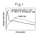
- the inventors engaged in studies and as a result discovered by when applying an impact bending load from a direction vertical to the longitudinal direction of a member as shown in FIG. 1, there is a high peak of bending repulsion at the start of impact at a rectangular tube compared with the bending repulsion at the start of impact of a round tube and that to improve the bending repulsion at the start of impact, it is important to keep buckling of the corner parts of a rectangular tube extremely small and to make the load be applied to the ends of the two side surfaces parallel to the bending input direction.
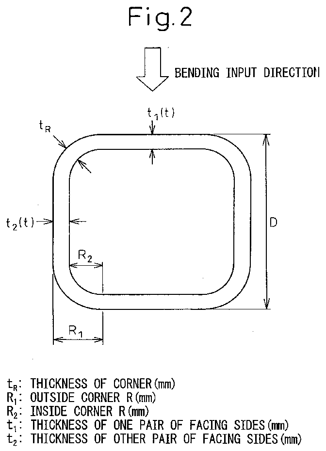
- an automobile strength member comprising a rectangular steel tube with a square cross-section, simultaneously satisfying the following relations (1) to (3), and having a strength of at least 690 MPa in terms of tensile strength: R 1 ⁇ 1.5t t R ⁇ 1.1t R 1 ⁇ R 2 where, t: thickness of side (mm) t R : thickness of corner (mm) R 1 : outside corner R (mm) R 2 : inside corner R (mm)
- an automobile structural member wherein both a maximum value and minimum value of hardness at a cross-section of the rectangular steel tube are in the range of within ⁇ 30% of the average value of the entire cross-section.
- an automobile strength member comprised of a rectangular tube having a square cross-section simultaneously satisfying the relations (4) and (5): 0.50 ⁇ t 1 /t 2 ⁇ 0.95 R 1 ⁇ 1.5t 2 where, t 1 : thickness of pair of facing sides (mm) t 2 : thickness of other pair of facing sides (mm) R 1 : outside corner R (mm)
- an automobile structural member comprised of a rectangular tube having a square cross-section for an automobile strength member as set forth in a third aspect of the invention arranged so that the thickness t 2 sides match the bending input direction.
- the corner thickness (t R ) of the corners By making the thickness (t R ) of the corners greater, the buckling resistance of the corners becomes larger and a load can be directly applied from the ends of the two side surfaces parallel to the bending input direction. If the corner thickness (t R ) is less than 1.1 times the side thicknesses, it is not effective. Therefore, the corner thickness (t R ) has to be made at least 1.1 times the side thicknesses as shown in relation (2). Further, here, the corner thickness (t R ) means the thickness of the thickest part of the corners. t R ⁇ 1.1t
- the tensile strength of the member is less than 690 MPa, a high bending strength at the beginning of impact is not obtained, so the tensile strength of the member is made at least 690 MPa. Note that if the tensile strength of the member is too high, brittle fracture and hydrogen induced cracking of the member become a concern, so the tensile strength of the member is preferably less than 1470 MPa.
- the second aspect of the invention defines the maximum value and minimum value of the cross-sectional hardness of the rectangular steel tube as being in the range of ⁇ 30% of the average value of the cross-section as a whole. If this range is exceeded, the ductility becomes remarkably lower at the position of the maximum value of the cross-sectional hardness. Brittle fracture becomes easier at this position.
- the thickness of one pair of facing sides is made (t 1 )
- the thickness of the other pair of facing sides parallel to the bending input direction is made (t 2 )
- t 1 is made smaller than t 2 .
- the two side surfaces parallel to the bending input direction are strengthened and the bending repulsion at the beginning of impact becomes higher.
- t 1 is made too small, the t 1 sides themselves may buckle, so the ratio of t 1 /t 2 must be made at least 0.50.
- t 1 /t 2 has to satisfy the conditions of the following relation (4): 0.50 ⁇ t 1 /t 2 ⁇ 0.95
- the methods of production of a round tube serving as an automobile strength member of the present invention include drawing, rolling, extrusion, etc.
- the material for forming the automobile strength member is generally a steel material, but in the third aspect of the invention, if the conditions are satisfied, it is also possible to use light metal materials of aluminum, titanium, magnesium, or alloys of the same or other light weight materials.
- the fourth aspect of the invention will be explained.
- the automobile strength member according to the third aspect of the invention When installing the automobile strength member according to the third aspect of the invention in an automobile, it is necessary to orient it so as to enable the bending properties to be exhibited to the maximum extent. That is, when installing it so that the sides of the thickness t 2 thicker than one pair of facing sides become parallel to the bending input direction, the most effective automobile strength member can be obtained.
- the bending repulsion at the beginning of impact is particularly important, so the bending repulsion at the start of impact was investigated by an impact bending test.
- the test conditions were a longitudinal direction length L of the test piece of 900 mm, a drop speed of 4.43 m/sec by a drop weight tester, a drop weight mass of 50 kg, and a bending span length L of 700 mm.
- the supports at the two ends were fixed.
- FIG. 2 shows the cross-sectional shape of a rectangular tube.
- D is the length dimension of one side (outside diameter) of the square cross-section.
- Table 1 shows various types of automobile strength members.
- a conventional door guard bar uses a 1470 Mpa class round steel tube ( ⁇ 35.0 x t2.3 mm), so the rates of rise of the bending repulsion at the beginning of impact and the weight ratio with respect to a round steel tube (symbol H) are compared.
- the hardness of the cross-section is measured to find the difference between the maximum value and minimum value of the cross-sectional hardnesses and the average value of the cross-sectional hardness.
- the hardness was measured at 1 mm pitches so as to satisfy the JIS standards (JIS Z 2244) by the Vicker's hardness test method.
- Materials A and B of the examples of the present invention have higher bending repulsions at the beginning of impact regardless of being light in weight.
- Material C of an example of the present invention does not have that high a bending repulsion at the beginning of impact compared with Material H, but the amount of reduction of the weight is large. There is a high effect of reduction of weight of the automobile member.
- Comparative Materials D, E, F, and G have a lower bending repulsion at the start of impact and reduction of weight compared with Prior Material H. That is, D has an R 1 of over 1.5t, E has a t R of less than 1.1t, and F has a small tensile strength - all outside of the scope of the present invention.
- the difference between the maximum value and minimum value of the cross-sectional hardness of Material G and the average of cross-sectional hardness is 33.8%.
- Table 2 shows automobile strength members with different side thicknesses.
- the bending input direction of the automobile strength members in an impact bending test shown in Table 2 was parallel to the thickness t 2 sides.
- the rates of rise of the bending repulsion at the beginning of the impact and weight ratios for rectangular tubes with uniform side thicknesses (no. 7) were compared.
- Materials 1, 2, and 3 of the examples of the present invention had higher bending repulsions at the beginning of impact compared with Comparative Material 7 and had weights substantially the same as Material 7.
- Comparative Materials 4 and 5 had slight increases in weight, but the bending repulsions at the beginning of the impact were not that high compared with Material 7.
- Comparative Material 6 exhibited an extremely high bending repulsion at the beginning of impact, but had a large thickness t 2 and became too heavy a weight and therefore was not preferable.
- an automobile strength member having a cross-sectional shape giving a high bending repulsion at the beginning of impact and able to reduce the production cost and lighten the weight and achieve a greater improvement in safety and a reduction of cost of an automobile.
Landscapes
- Engineering & Computer Science (AREA)
- Mechanical Engineering (AREA)
- Chemical & Material Sciences (AREA)
- Combustion & Propulsion (AREA)
- Transportation (AREA)
- Architecture (AREA)
- Structural Engineering (AREA)
- Manufacturing & Machinery (AREA)
- Physics & Mathematics (AREA)
- Thermal Sciences (AREA)
- Crystallography & Structural Chemistry (AREA)
- Materials Engineering (AREA)
- Metallurgy (AREA)
- Organic Chemistry (AREA)
- Body Structure For Vehicles (AREA)
Abstract
Description
- The present invention relates to an automobile strength member high in bending repulsion at the beginning of impact and able to reduce production costs and lighten the weight.
- In recent years, standards for side impact of automobiles have become tougher. The structural design concepts of chasses have changed as well. Automobile doors are being provided with door guard bars. In the past, door guard bars have been considered members deforming at the time of side impact so as to absorb the impact energy and reduce the impact received by passengers.
- In recent years, chassis structures have been designed to enable the impact energy at the time of a side impact to be absorbed by the door as a whole. In such a chassis structure, the door guard bar has been used as an energy transmitting member for transmitting the impact energy to other members around the door guard bar to have the other members absorb the impact energy by their own deformation. Therefore, it is important that the member used as the door guard bar keep any impact force received to within its elastic deformation range and not deform. In particular, a member having the property of a high bending repulsion at the beginning of impact has been demanded. For this, increase of the strength of the member may be considered, but a higher strength results in the problems of brittle fracture or hydrogen induced cracking. Just increasing the strength of the member is not preferable for an automobile member. Therefore, the shape was focused on and studied for improvement of the bending repulsion at the beginning of impact.
- Up to now, members for door guard bars have been studied using static bending test from the viewpoint of the absorption energy. For example, it is known that a high absorption energy can be obtained by increasing the strength of a steel tube while its cross-section is round (for example, see Japanese Unexamined Patent Publication (Kokai) No. H4-63242). However, in bending deformation behavior of a round-section steel tube, the load concentrates right under the load, and the sectional shape easily flattens due to local buckling. The member is similarly weak in impact bending. Therefore, a high bending repulsion at the start of impact cannot be obtained.
- Further, an automobile structural member having a closed sectional structure, a maximum dimension in the longitudinal direction, a maximum dimension in the direction perpendicular to that, an outer circumferential length, and a thickness defined in relationship by a tensile strength of at least 1400 MPa has been proposed (for example, see Japanese Unexamined Patent Publication (Kokai) No. 2002-248941). With this member, it is true that the absorption energy and bending repulsion are improved compared with the past, but in each case the results were based on a static bending test. Whether a high bending repulsion at the beginning of impact is obtained even for an impact bending test is unclear.
- On the other hand, as opposed to this, rectangular tubes superior in bending properties compared with round tubes are being developed. That is, there has been proposed a rectangular tube wherein the outsides of the corner parts are either not provided with an R or are providing with an R of a magnitude less than the thickness and the inner surfaces are provided with an R larger than the outside so as to make a load act directly on the two side surfaces parallel to the bending input direction and improve the bending repulsion (for example, see Japanese Unexamined Patent Publication (Kokai) No. H6-278458). The tensile strength of the member is the 1470 MPa class. With a member having this tensile strength, the possibility arises of brittle fracture or hydrogen induced cracking occurring due to the bending load applied. Further, when further working an electric resistance welded steel tube or other round tube into a rectangular tube, provision of a larger R at the inner surfaces of the corner parts than the outer surfaces is difficult in production, while when producing the above sectional shape, there is the problem that the cost ends up becoming remarkably higher.
- As explained above, members for door guard bars have been studied up to now by static bending test from the viewpoint of improvement of the absorption energy in the range of plastic deformation. In impact bending, however, it is unclear if a high bending repulsion is obtained at the beginning of impact. Further, since the members are high in strength, there is a possibility of brittle fracture and hydrogen induced cracking occurring. Further, when working an electric resistance welded steel tube or other round tube into a rectangular tube, provision of a larger R at the inside surface than the outside surface is difficult in production, while when producing the above sectional shape, there is the problem that the cost ends up becoming remarkably higher.
- An object of the present invention is therefore to provide an automobile strength member having a cross-sectional shape having a high bending repulsion at the beginning of impact and enabling a reduction in the production cost and lightening of the weight.
- As explained above, a door guard bar member has to keep the impact force within the range of its elastic deformation and not deform at the time of side impact. In particular, it is required to exhibit a high bending repulsion at the beginning of impact.
- The inventors engaged in studies and as a result discovered by when applying an impact bending load from a direction vertical to the longitudinal direction of a member as shown in FIG. 1, there is a high peak of bending repulsion at the start of impact at a rectangular tube compared with the bending repulsion at the start of impact of a round tube and that to improve the bending repulsion at the start of impact, it is important to keep buckling of the corner parts of a rectangular tube extremely small and to make the load be applied to the ends of the two side surfaces parallel to the bending input direction.
- To keep the buckling of the corner parts of a rectangular tube extremely small, it is effective to reduce the R of the outside corner parts and make the thickness greater. Further, to cause the load to be applied directly to the ends of the two side surfaces parallel to the bending input direction, it is effective to greatly reduce the R of the outside corner parts from the thickness of the sides. In this case, the thickness of the sides other than the corner parts is constant. Further, even if making the thickness of the two side surfaces where the load is directly applied greater, the inventors discovered that the two side surfaces are reinforced and the bending repulsion at the beginning of impact becomes higher. Further, it is effective to increase the strength of the member. If the tensile strength of the member is too high, brittle fracture or hydrogen induced cracking become a concern.
- On the other hand, from the viewpoint of production cost, by making the R of the outside corner parts larger than the R of the inside corner parts, production becomes easier and the production costs can be reduced.
Thus, the object above can be achieved by the features defined in the claims. - To attain the above object, according to a first aspect of the invention, there is provided an automobile strength member comprising a rectangular steel tube with a square cross-section, simultaneously satisfying the following relations (1) to (3), and having a strength of at least 690 MPa in terms of tensile strength:
tR: thickness of corner (mm)
R1: outside corner R (mm)
R2: inside corner R (mm) - According to a second aspect of the invention, there is provided an automobile structural member wherein both a maximum value and minimum value of hardness at a cross-section of the rectangular steel tube are in the range of within ±30% of the average value of the entire cross-section.
- According to a third aspect of the invention, there is provided an automobile strength member comprised of a rectangular tube having a square cross-section simultaneously satisfying the relations (4) and (5):
t2: thickness of other pair of facing sides (mm)
R1: outside corner R (mm) - According to a fourth aspect of the invention, there is provided an automobile structural member comprised of a rectangular tube having a square cross-section for an automobile strength member as set forth in a third aspect of the invention arranged so that the thickness t2 sides match the bending input direction.
- These and other objects and features of the present invention will become clearer from the following description of the preferred embodiments given with reference to the attached drawings, wherein:
- FIG. 1 is a view comparing displacement-bending repulsion curves of rectangular tubes and round tubes in impact bending, and
- FIG. 2 is a view explaining the sectional shape of a rectangular tube.
-
- Below, the present invention will be explained in more detail. First, the first aspect of the invention will be expained.
- To improve the bending repulsion at the beginning of impact, by making the buckling of the corner parts extremely small and making the impact directly act on the ends of the two side surfaces parallel to the bending input direction, it is necessary to make flattening of the cross-section more difficult.
- If the R of the outside corners (R1) is too large, no load directly acts on the ends of the two side surfaces parallel to the bending input direction, the two side surfaces parallel to the bending input direction bulge outward due to only the center side at the input side vertical to the bending input direction being pressed, and flattening of the cross-section easily occurs. As a result, the bending repulsion at the beginning of impact falls. In particular, if the R (R1) of the outside corners exceeds 1.5 times the thickness (t), the bending repulsion at the beginning of impact remarkably falls. Therefore, the outside corner R1 is made not more than 1.5 times the thickness as in relation (1):
- Further, to greatly reduce the buckling of the corner parts, it is also effective to make the thickness (tR) of the corners greater.
- By making the thickness (tR) of the corners greater, the buckling resistance of the corners becomes larger and a load can be directly applied from the ends of the two side surfaces parallel to the bending input direction. If the corner thickness (tR) is less than 1.1 times the side thicknesses, it is not effective. Therefore, the corner thickness (tR) has to be made at least 1.1 times the side thicknesses as shown in relation (2). Further, here, the corner thickness (tR) means the thickness of the thickest part of the corners.
- On the other hand, making the outside corner R (R1) larger than the inside corner R (R2) facilitates production and reduces the production costs. That is, the following relation (3) has to be satisfied:
- When the tensile strength of the member is less than 690 MPa, a high bending strength at the beginning of impact is not obtained, so the tensile strength of the member is made at least 690 MPa. Note that if the tensile strength of the member is too high, brittle fracture and hydrogen induced cracking of the member become a concern, so the tensile strength of the member is preferably less than 1470 MPa.
- The rectangular steel tube with a high bending repulsion at the beginning of impact and with a reduced production cost simultaneously satisfies the conditions of the above relations (1), (2), and (3) and the tensile strength has to be at least 690 MPa. If even one of these conditions is not satisfied, the high bending repulsion at the beginning of impact and the reduced production cost cannot both be achieved.
- Next, the second aspect of the invention will be explained.
- The second aspect of the invention defines the maximum value and minimum value of the cross-sectional hardness of the rectangular steel tube as being in the range of ±30% of the average value of the cross-section as a whole. If this range is exceeded, the ductility becomes remarkably lower at the position of the maximum value of the cross-sectional hardness. Brittle fracture becomes easier at this position.
- Next, the third aspect of the invention will be explained.
- For improving the bending repulsion at the beginning of impact, making the thickness of the sides different is also effective. That is, here, the thickness of one pair of facing sides is made (t1), the thickness of the other pair of facing sides parallel to the bending input direction is made (t2), and t1 is made smaller than t2. When making the thickness of the sides parallel to the bending input direction a thicker t2, the two side surfaces parallel to the bending input direction are strengthened and the bending repulsion at the beginning of impact becomes higher. However, if t1 is made too small, the t1 sides themselves may buckle, so the ratio of t1/t2 must be made at least 0.50. On the other hand, if the ratio of t1/t2 exceeds 0.95, the amount of rise of the bending repulsion at the beginning of impact becomes smaller. This is not preferable from the viewpoint of the improvement of the bending repulsion at the beginning of impact. Therefore, t1/t2 has to satisfy the conditions of the following relation (4):
- Further, in this case, as explained in relation (1), the outside corner R (R1) should be not more than 1.5 times the thickness (t2) of the thicker sides. Therefore, it is necessary that the relation (5) be satisfied:
- The methods of production of a round tube serving as an automobile strength member of the present invention include drawing, rolling, extrusion, etc.
- Further, the material for forming the automobile strength member is generally a steel material, but in the third aspect of the invention, if the conditions are satisfied, it is also possible to use light metal materials of aluminum, titanium, magnesium, or alloys of the same or other light weight materials. Next, the fourth aspect of the invention will be explained.
- When installing the automobile strength member according to the third aspect of the invention in an automobile, it is necessary to orient it so as to enable the bending properties to be exhibited to the maximum extent. That is, when installing it so that the sides of the thickness t2 thicker than one pair of facing sides become parallel to the bending input direction, the most effective automobile strength member can be obtained.
- In the automobile strength member of the present invention, the bending repulsion at the beginning of impact is particularly important, so the bending repulsion at the start of impact was investigated by an impact bending test. The test conditions were a longitudinal direction length L of the test piece of 900 mm, a drop speed of 4.43 m/sec by a drop weight tester, a drop weight mass of 50 kg, and a bending span length L of 700 mm. The supports at the two ends were fixed.
- FIG. 2 shows the cross-sectional shape of a rectangular tube. Here, D is the length dimension of one side (outside diameter) of the square cross-section.
- Table 1 shows various types of automobile strength members. A conventional door guard bar uses a 1470 Mpa class round steel tube (35.0 x t2.3 mm), so the rates of rise of the bending repulsion at the beginning of impact and the weight ratio with respect to a round steel tube (symbol H) are compared. Here, the hardness of the cross-section is measured to find the difference between the maximum value and minimum value of the cross-sectional hardnesses and the average value of the cross-sectional hardness. The hardness was measured at 1 mm pitches so as to satisfy the JIS standards (JIS Z 2244) by the Vicker's hardness test method. Materials A and B of the examples of the present invention have higher bending repulsions at the beginning of impact regardless of being light in weight. Material C of an example of the present invention does not have that high a bending repulsion at the beginning of impact compared with Material H, but the amount of reduction of the weight is large. There is a high effect of reduction of weight of the automobile member. As opposed to this, Comparative Materials D, E, F, and G have a lower bending repulsion at the start of impact and reduction of weight compared with Prior Material H. That is, D has an R1 of over 1.5t, E has a tR of less than 1.1t, and F has a small tensile strength - all outside of the scope of the present invention. The difference between the maximum value and minimum value of the cross-sectional hardness of Material G and the average of cross-sectional hardness is 33.8%. This ends up being far higher than the less than 30% in the present invention. At the portion of a large cross-sectional hardness, the ductility remarkably falls and brittle fracture becomes easier. When producing a rectangular tube from an electric resistance welded steel tube or other round steel tube by the continuous rolling method, the welds remain as welded, so the 30% of the present invention is exceeded. On the other hand, a member produced from Material C by drawing is obtained by producing a round steel tube, then heat treating it to make the quality of the welds and base metal equal, so the difference between the maximum value and the minimum value of the cross-sectional hardness and the average of the cross-sectional hardness becomes 10.5% or within 30% in the present invention.
- Table 2 shows automobile strength members with different side thicknesses. The bending input direction of the automobile strength members in an impact bending test shown in Table 2 was parallel to the thickness t2 sides. Here, the rates of rise of the bending repulsion at the beginning of the impact and weight ratios for rectangular tubes with uniform side thicknesses (no. 7) were compared. Materials 1, 2, and 3 of the examples of the present invention had higher bending repulsions at the beginning of impact compared with Comparative Material 7 and had weights substantially the same as Material 7. As opposed to this, Comparative Materials 4 and 5 had slight increases in weight, but the bending repulsions at the beginning of the impact were not that high compared with Material 7. Comparative Material 6 exhibited an extremely high bending repulsion at the beginning of impact, but had a large thickness t2 and became too heavy a weight and therefore was not preferable.

- According to the present invention, it is possible to provide an automobile strength member having a cross-sectional shape giving a high bending repulsion at the beginning of impact and able to reduce the production cost and lighten the weight and achieve a greater improvement in safety and a reduction of cost of an automobile.
- While the invention has been described with reference to specific embodiments chosen for purpose of illustration, it should be apparent that numerous modifications could be made thereto by those skilled in the art without departing from the basic concept and scope of the invention.
Claims (4)
- An automobile strength member comprising a rectangular steel tube with a square cross-section, simultaneously satisfying the following relations (1) to (3), and having a strength of at least 690 MPa in terms of tensile strength:
tR: thickness of corner (mm)
R1: outside corner R (mm)
R2: inside corner R (mm) - An automobile strength member as set forth in claim 1, wherein both a maximum value and minimum value of hardness at a cross-section of said rectangular steel tube are in the range of within ±30% of the average value of the entire cross-section.
- An automobile strength member comprising a rectangular tube having a square cross-section simultaneously satisfying the relations (4) and (5):
t2: thickness of other pair of facing sides (mm)
R1: outside corner R (mm) - An automobile structural member comprising a rectangular tube of a square cross-section for an automobile strength member as set forth in claim 3 arranged so that the thickness t2 sides match the bending input direction.
Applications Claiming Priority (2)
| Application Number | Priority Date | Filing Date | Title |
|---|---|---|---|
| JP2003345626A JP4388340B2 (en) | 2003-10-03 | 2003-10-03 | Strength members for automobiles |
| JP2003345626 | 2003-10-03 |
Publications (3)
| Publication Number | Publication Date |
|---|---|
| EP1520741A2 true EP1520741A2 (en) | 2005-04-06 |
| EP1520741A3 EP1520741A3 (en) | 2007-03-07 |
| EP1520741B1 EP1520741B1 (en) | 2013-05-15 |
Family
ID=34309159
Family Applications (1)
| Application Number | Title | Priority Date | Filing Date |
|---|---|---|---|
| EP04023394.2A Expired - Lifetime EP1520741B1 (en) | 2003-10-03 | 2004-10-01 | Automobile strength member, particularly side impact beam |
Country Status (5)
| Country | Link |
|---|---|
| US (1) | US7648191B2 (en) |
| EP (1) | EP1520741B1 (en) |
| JP (1) | JP4388340B2 (en) |
| KR (1) | KR100619295B1 (en) |
| CN (1) | CN1325837C (en) |
Cited By (2)
| Publication number | Priority date | Publication date | Assignee | Title |
|---|---|---|---|---|
| EP2527233A1 (en) * | 2007-04-04 | 2012-11-28 | Sumitomo Metal Industries, Ltd. | Strength member for an automobile body |
| US20220126656A1 (en) * | 2019-01-15 | 2022-04-28 | Nippon Steel Corporation | Automobile door |
Families Citing this family (16)
| Publication number | Priority date | Publication date | Assignee | Title |
|---|---|---|---|---|
| JP4388340B2 (en) * | 2003-10-03 | 2009-12-24 | 新日本製鐵株式会社 | Strength members for automobiles |
| JP4572674B2 (en) * | 2004-12-02 | 2010-11-04 | 住友金属工業株式会社 | Shock absorbing member |
| DE102009039710B4 (en) * | 2009-08-28 | 2014-03-20 | V&M Deutschland Gmbh | Method for producing hot-rolled hollow sections with small edge radii, hollow profile and use of the hollow profile |
| US8727421B2 (en) | 2011-08-31 | 2014-05-20 | Shape Corp. | Door beam assembly with roll formed beam |
| KR101381115B1 (en) * | 2012-05-16 | 2014-04-04 | (주)피에스테크 | Steel pipe strut |
| US9937902B2 (en) | 2013-11-21 | 2018-04-10 | Paul L. Klassy | Landing gear with cross-port disable valve and supplemental electronic limit switch travel limiter |
| US9469281B2 (en) | 2013-11-21 | 2016-10-18 | Paul L. Klassy | External mid-mount drive for powered landing gear with cross-port disable valve travel limiter |
| JP6170895B2 (en) * | 2014-10-22 | 2017-07-26 | 株式会社神戸製鋼所 | Collision resistant parts for automobiles |
| US9821854B2 (en) | 2015-11-24 | 2017-11-21 | Honda Motor Co., Ltd. | Side sill for a vehicle body |
| BR112019001040A2 (en) * | 2016-07-28 | 2019-04-30 | Nippon Steel & Sumitomo Metal Corporation | external automotive panel |
| JP6322329B1 (en) | 2017-11-22 | 2018-05-09 | 株式会社神戸製鋼所 | Door beam |
| US11173771B2 (en) * | 2018-01-26 | 2021-11-16 | Nippon Steel Corporation | Impact absorption member |
| CN110726064A (en) * | 2018-07-17 | 2020-01-24 | 欣诺冷弯型钢产业研究院(曹妃甸)有限公司 | Corner thickened cold-hot composite molded square rectangular steel pipe and preparation method thereof |
| WO2020196837A1 (en) * | 2019-03-28 | 2020-10-01 | 日本製鉄株式会社 | Framework member and vehicle body structure |
| CN114026014B (en) * | 2019-06-28 | 2024-06-11 | 日本制铁株式会社 | Shock absorbing member, method for producing the shock absorbing member, and method for producing steel sheet for cold plastic working |
| CN111422042A (en) * | 2020-04-03 | 2020-07-17 | 中铝材料应用研究院有限公司 | Truck cab door |
Family Cites Families (36)
| Publication number | Priority date | Publication date | Assignee | Title |
|---|---|---|---|---|
| US3209432A (en) * | 1963-12-23 | 1965-10-05 | Ford Motor Co | Method for fabricating a structural member |
| SE434245B (en) * | 1982-02-01 | 1984-07-16 | Dobel Ab | SAFETY BODY, AND PROCEDURE FOR ITS PREPARATION |
| GB8505491D0 (en) | 1985-03-04 | 1985-04-03 | Bekaert Sa Nv | Heat treatment of steel |
| US4826238A (en) * | 1986-12-01 | 1989-05-02 | Honda Giken Kogyo Kabushiki Kaisha | Side sill for automotive vehicle |
| JP2811226B2 (en) | 1990-07-02 | 1998-10-15 | 新日本製鐵株式会社 | Steel pipe for body reinforcement |
| JPH0463720A (en) * | 1990-07-03 | 1992-02-28 | Masanobu Nakamura | Shock absorbing material for car body |
| JP2933996B2 (en) * | 1990-07-18 | 1999-08-16 | 新日本製鐵株式会社 | Steel pipe for body reinforcement |
| US5232261A (en) * | 1992-06-04 | 1993-08-03 | Nhk Spring Co., Ltd. | Door impact beam for an automobile |
| JPH06534A (en) | 1992-06-18 | 1994-01-11 | Nippon Steel Corp | Ultra high-tension electric resistance-welded tube excellent in bending characteristic |
| JPH06106978A (en) * | 1992-09-29 | 1994-04-19 | Nippon Steel Corp | Ultra high tensile deformed ERW steel pipe with excellent bending properties |
| JPH06199193A (en) * | 1993-01-06 | 1994-07-19 | Nippon Steel Corp | Automotive bumper reinforcement |
| JP3211451B2 (en) * | 1993-02-05 | 2001-09-25 | アイシン精機株式会社 | Vehicle impact beam |
| JPH06278458A (en) | 1993-03-29 | 1994-10-04 | Nippon Steel Corp | Square pipe for automobile door reinforcing material |
| JP3779335B2 (en) * | 1993-09-22 | 2006-05-24 | 日本発条株式会社 | Vehicle door beam with cab-over cab |
| JP3023657B2 (en) * | 1995-09-25 | 2000-03-21 | 本田技研工業株式会社 | Rear swing arm of motorcycle |
| JP2990057B2 (en) * | 1996-03-13 | 1999-12-13 | アイシン軽金属株式会社 | Energy absorption structure on the side of the vehicle |
| DE19733191A1 (en) * | 1997-07-31 | 1999-02-18 | Porsche Ag | Cross beams for vehicles |
| US6513242B1 (en) * | 1997-08-15 | 2003-02-04 | Dana Corporation | Method of manufacturing a vehicle body and frame assembly including hydroformed side rails |
| US5813719A (en) * | 1997-09-25 | 1998-09-29 | Trim Trends, Inc. | Side intrusion beam assembly having compensating welds at brackets |
| US5868456A (en) * | 1997-09-29 | 1999-02-09 | Trim Trends, Inc. | Selectively heat treated side intrusion beams and method for making the same |
| JP3266099B2 (en) * | 1998-03-27 | 2002-03-18 | 株式会社神戸製鋼所 | Aluminum alloy door beam |
| US6020039A (en) * | 1998-04-21 | 2000-02-01 | Inland Steel Company | Automobile door impact beam |
| JP3887542B2 (en) * | 2001-02-26 | 2007-02-28 | 新日本製鐵株式会社 | Structural members for automobiles |
| JP3854812B2 (en) * | 2001-03-27 | 2006-12-06 | 新日本製鐵株式会社 | Strength members for automobiles |
| US6722037B2 (en) * | 2001-12-06 | 2004-04-20 | Shape Corporation | Variable thickness tubular doorbeam |
| SE523371C2 (en) | 2001-08-31 | 2004-04-13 | Accra Teknik Ab | Beam |
| EP1329363A1 (en) * | 2002-01-16 | 2003-07-23 | Alcan Technology & Management AG | Deformable motor vehicle energy absorbing member |
| JP3967926B2 (en) * | 2002-01-17 | 2007-08-29 | アイシン精機株式会社 | Automotive door impact beam |
| DE10320971B3 (en) * | 2003-05-09 | 2004-09-16 | Dr.Ing.H.C. F. Porsche Ag | Side impact protection unit for vehicle doors has a balancing fracture point in a side impact support or in a console at a distance from the fixing fracture point |
| JP4388340B2 (en) * | 2003-10-03 | 2009-12-24 | 新日本製鐵株式会社 | Strength members for automobiles |
| WO2005058625A1 (en) * | 2003-12-17 | 2005-06-30 | Sumitomo Metal Industries Ltd. | Metal tube for reinforcing vehicle body and member for reinforcing vehicle body using the same |
| US20050279049A1 (en) * | 2004-06-22 | 2005-12-22 | Mackenzie Steven K | Internally reinforced hydroformed assembly and method of making same |
| US7188876B2 (en) * | 2004-09-14 | 2007-03-13 | General Electric Company | Bumper assembly including energy absorber with vertical translation crush lobes |
| DE102005036292B4 (en) * | 2005-03-21 | 2007-11-08 | Dura Automotive Plettenberg Entwicklungs- Und Vertriebs Gmbh | Side impact beam for a motor vehicle |
| DE102005062299A1 (en) * | 2005-12-24 | 2007-06-28 | Dr.Ing.H.C. F. Porsche Ag | Motor vehicle door with a side impact protection device |
| DE102006060052A1 (en) * | 2006-12-19 | 2008-06-26 | Trw Airbag Systems Gmbh | Vehicle impact protection system |
-
2003
- 2003-10-03 JP JP2003345626A patent/JP4388340B2/en not_active Expired - Lifetime
-
2004
- 2004-09-30 US US10/956,918 patent/US7648191B2/en active Active
- 2004-10-01 EP EP04023394.2A patent/EP1520741B1/en not_active Expired - Lifetime
- 2004-10-01 KR KR1020040078426A patent/KR100619295B1/en not_active Expired - Fee Related
- 2004-10-08 CN CNB2004100807248A patent/CN1325837C/en not_active Expired - Fee Related
Non-Patent Citations (1)
| Title |
|---|
| None |
Cited By (3)
| Publication number | Priority date | Publication date | Assignee | Title |
|---|---|---|---|---|
| EP2527233A1 (en) * | 2007-04-04 | 2012-11-28 | Sumitomo Metal Industries, Ltd. | Strength member for an automobile body |
| US20220126656A1 (en) * | 2019-01-15 | 2022-04-28 | Nippon Steel Corporation | Automobile door |
| US11673455B2 (en) * | 2019-01-15 | 2023-06-13 | Nippon Steel Corporation | Automobile door |
Also Published As
| Publication number | Publication date |
|---|---|
| CN1325837C (en) | 2007-07-11 |
| EP1520741A3 (en) | 2007-03-07 |
| KR20050033455A (en) | 2005-04-12 |
| KR100619295B1 (en) | 2006-09-12 |
| EP1520741B1 (en) | 2013-05-15 |
| JP4388340B2 (en) | 2009-12-24 |
| US20050073170A1 (en) | 2005-04-07 |
| JP2005112031A (en) | 2005-04-28 |
| CN1603676A (en) | 2005-04-06 |
| US7648191B2 (en) | 2010-01-19 |
Similar Documents
| Publication | Publication Date | Title |
|---|---|---|
| EP1520741A2 (en) | Automobile strength member, particularly side impact beam | |
| US5277469A (en) | Motor vehicle door reinforcement tube and a process for manufacturing the reinforcement tube | |
| JP4934283B2 (en) | Body reinforcement members | |
| US11945053B2 (en) | Tailored blank, tailored blank manufacturing method, stamped part, and stamped part manufacturing method | |
| KR101719944B1 (en) | Impact-absorbing component | |
| EP2060646B1 (en) | Stainless steel sheet for structural members excellent in impact -absorbing characteristics | |
| JP5420462B2 (en) | Automotive parts | |
| CA2470989A1 (en) | Multiple material bumper beam | |
| EP1364821B1 (en) | Structural member of automobile and automobile body comprising it | |
| WO2011126146A1 (en) | Collision energy absorbing structure | |
| EP3932750B1 (en) | Structural member for vehicle | |
| JP2003129611A (en) | Bending strength member | |
| Sperle et al. | High strength and ultra high strength steels for weight reduction in structural and safety-related applications | |
| JP3029514B2 (en) | Aluminum alloy car door reinforcement | |
| Olsson et al. | New advanced ultra-high strength steels for the automotive industry | |
| JP4734129B2 (en) | Automotive strength members with excellent impact characteristics | |
| JP5179396B2 (en) | Shock absorbing member | |
| RU2711173C1 (en) | Reinforcing structure for cargo vehicle cabin and cargo vehicle cabin | |
| JP4143015B2 (en) | Automotive reinforcement | |
| JPH11222031A (en) | Impact beam | |
| Kaneko et al. | High-strength hot-rolled sheet steel with excellent crashworthiness induced by strain age hardening | |
| JP2006137376A (en) | Strength member for automobile having excellent collision characteristics and structural member for automobile using the same | |
| JPH07186722A (en) | Automobile reinforcing member made of aluminum alloy | |
| JPH09207566A (en) | Reinforcing pipe for automobile door | |
| DE102010011973A1 (en) | Method for producing a door impact beam |
Legal Events
| Date | Code | Title | Description |
|---|---|---|---|
| PUAI | Public reference made under article 153(3) epc to a published international application that has entered the european phase |
Free format text: ORIGINAL CODE: 0009012 |
|
| 17P | Request for examination filed |
Effective date: 20041101 |
|
| AK | Designated contracting states |
Kind code of ref document: A2 Designated state(s): AT BE BG CH CY CZ DE DK EE ES FI FR GB GR HU IE IT LI LU MC NL PL PT RO SE SI SK TR |
|
| AX | Request for extension of the european patent |
Extension state: AL HR LT LV MK |
|
| PUAL | Search report despatched |
Free format text: ORIGINAL CODE: 0009013 |
|
| AK | Designated contracting states |
Kind code of ref document: A3 Designated state(s): AT BE BG CH CY CZ DE DK EE ES FI FR GB GR HU IE IT LI LU MC NL PL PT RO SE SI SK TR |
|
| AX | Request for extension of the european patent |
Extension state: AL HR LT LV MK |
|
| AKX | Designation fees paid |
Designated state(s): DE FR GB |
|
| 17Q | First examination report despatched |
Effective date: 20081211 |
|
| GRAP | Despatch of communication of intention to grant a patent |
Free format text: ORIGINAL CODE: EPIDOSNIGR1 |
|
| RAP1 | Party data changed (applicant data changed or rights of an application transferred) |
Owner name: NIPPON STEEL & SUMITOMO METAL CORPORATION |
|
| GRAS | Grant fee paid |
Free format text: ORIGINAL CODE: EPIDOSNIGR3 |
|
| GRAA | (expected) grant |
Free format text: ORIGINAL CODE: 0009210 |
|
| AK | Designated contracting states |
Kind code of ref document: B1 Designated state(s): DE FR GB |
|
| REG | Reference to a national code |
Ref country code: GB Ref legal event code: FG4D |
|
| REG | Reference to a national code |
Ref country code: DE Ref legal event code: R096 Ref document number: 602004042095 Country of ref document: DE Effective date: 20130711 |
|
| PLBE | No opposition filed within time limit |
Free format text: ORIGINAL CODE: 0009261 |
|
| STAA | Information on the status of an ep patent application or granted ep patent |
Free format text: STATUS: NO OPPOSITION FILED WITHIN TIME LIMIT |
|
| 26N | No opposition filed |
Effective date: 20140218 |
|
| REG | Reference to a national code |
Ref country code: DE Ref legal event code: R097 Ref document number: 602004042095 Country of ref document: DE Effective date: 20140218 |
|
| REG | Reference to a national code |
Ref country code: FR Ref legal event code: PLFP Year of fee payment: 13 |
|
| REG | Reference to a national code |
Ref country code: FR Ref legal event code: PLFP Year of fee payment: 14 |
|
| REG | Reference to a national code |
Ref country code: FR Ref legal event code: PLFP Year of fee payment: 15 |
|
| REG | Reference to a national code |
Ref country code: DE Ref legal event code: R082 Ref document number: 602004042095 Country of ref document: DE Representative=s name: VOSSIUS & PARTNER PATENTANWAELTE RECHTSANWAELT, DE Ref country code: DE Ref legal event code: R081 Ref document number: 602004042095 Country of ref document: DE Owner name: NIPPON STEEL CORPORATION, JP Free format text: FORMER OWNER: NIPPON STEEL & SUMITOMO METAL CORPORATION, TOKYO, JP |
|
| PGFP | Annual fee paid to national office [announced via postgrant information from national office to epo] |
Ref country code: FR Payment date: 20190913 Year of fee payment: 16 |
|
| PGFP | Annual fee paid to national office [announced via postgrant information from national office to epo] |
Ref country code: GB Payment date: 20190926 Year of fee payment: 16 |
|
| PGFP | Annual fee paid to national office [announced via postgrant information from national office to epo] |
Ref country code: DE Payment date: 20190917 Year of fee payment: 16 |
|
| REG | Reference to a national code |
Ref country code: DE Ref legal event code: R119 Ref document number: 602004042095 Country of ref document: DE |
|
| GBPC | Gb: european patent ceased through non-payment of renewal fee |
Effective date: 20201001 |
|
| PG25 | Lapsed in a contracting state [announced via postgrant information from national office to epo] |
Ref country code: DE Free format text: LAPSE BECAUSE OF NON-PAYMENT OF DUE FEES Effective date: 20210501 Ref country code: FR Free format text: LAPSE BECAUSE OF NON-PAYMENT OF DUE FEES Effective date: 20201031 |
|
| PG25 | Lapsed in a contracting state [announced via postgrant information from national office to epo] |
Ref country code: GB Free format text: LAPSE BECAUSE OF NON-PAYMENT OF DUE FEES Effective date: 20201001 |