FIELD OF THE INVENTION
-
The present invention relates to a metal mold for
molding a plastic product which is made up of two or more
pieces and a method of molding such plastic product.
BACKGROUND OF THE INVENTION
-
It is well-known that a spectacle case H as shown in FIG.
15(a) is produced by a metal mold using two materials. The
spectacle case H is composed of a substantially boat-shaped
main body H1 for storing glasses or the like and a lid H2
that is rotatably connected to the main body H1 with hinge
portions J. As shown in FIG. 15(b), the hinge portions J are
so constructed that an insertion hole b formed in the main
body H1 supports an insertion portion (hinge pin) p formed on
the lid H2.
-
The aforementioned spectacle case H is produced using a
metal mold with a movable sleeve S. Specifically, the main
body H1 and the lid H2 shown in FIG. 15(b) are produced by
injecting heat-melted plastic resin into two cavity portions
made in the shapes of the main body H1 and the lid H2 under
pressure and then cooling the resin. In this specification,
the term "cavity portion" indicates a hollow portion in the
formed in a closed metal mold as a cavity or a hollow portion
formed between a cavity and a core.
-
In the aforementioned production process, the two cavity
portions are connected at the positions corresponding to the
insertion holes b and the insertion portions p in the hinge
portions J. The movable sleeve S acts as a core for
partitioning the heat melted plastic resin between the two
cavity portions and providing the shape of the insertion hole
b. After the plastic resin is cooled, when the movable
sleeve S is detached from the insertion hole b and the
insertion portion p as shown in the drawing, a space is
formed between the insertion hole b and the insertion portion
p.
-
In the case of molding a precision component, a play
between the insertion hole b and the insertion portion p
needs to be minimized. However, an extremely thin movable
sleeve S reduces the strength of the sleeve itself. For this
reason, it has been difficult to narrow the space between the
insertion hole b and the insertion portion p in accordance
with high precision requirements.
-
Further, when a collar or the like is provided to an
edge e of the insertion portion p so as to prevent the
insertion portion from coming off the insertion hole, the
spectacle case H is released from the metal mold and then,
the collar or the like, which is a separate component from
the insertion portion p, must be fixed to the edge e of the
insertion portion p in a later process. In other words, it
is not possible to produce a collar or the like having a
longer diameter than the outer diameter of the insertion
portion p on the edge e of the insertion portion p at the
same time when the spectacle case H is molded.
-
Accordingly, in order to solve the above problems, we
have eventually found the present invention. An object of
the present invention is to provide a metal mold of a simple
structure that can be used for producing a combined product
and a method of molding such combined product.
SUMMARY OF THE INVENTION
-
The present invention relates to a metal mold for
injection molding a combined product composed of a first
molded piece having an insertion hole and a second molded
piece having an insertion portion that is inserted into the
insertion hole. Such metal mold comprises: one or more first
piece molds for molding the first molded piece; one or more
second piece molds for molding the second molded piece; and
one or more pin cores that pass through a portion
corresponding to the insertion hole of the first piece mold
and the insertion portion of the second piece mold and that
are inserted into and removed from the first piece mold and
the second piece mold.
-
The present invention relates to a method of injection
molding a combined product composed of a first molded piece
having an insertion hole and a second molded piece having an
insertion portion that is inserted into the insertion hole.
Such method comprises the steps of: injection molding the
first molded piece from a first resin and forming the
insertion hole by a pin core; removing a part or whole of the
pin core from the first molded piece; and injection molding
the second molded piece from a second resin and forming the
insertion portion by the insertion hole of the first molded
piece.
-
The present invention relates to a method of injection
molding a combined product composed of a first molded piece
having an insertion hole and a second molded piece having
adjacent main molded portions and an insertion portion
between the main molded portions that is inserted into the
insertion hole. Such method comprises the steps of:
inserting a pin core that is used for forming the insertion
hole into a portion corresponding to the insertion hole of
the first piece mold and the insertion portion of the second
piece mold, filling a first resin in the first piece mold
for molding the first molded piece, removing the pin core
from the portion corresponding to the insertion hole of the
first piece mold and the insertion portion of the second
piece mold, and filling a second resin in the second piece
mold for molding the second molded piece.
-
Further, in the method of injection molding a combined
product according to the present invention, the second resin
has a higher mold shrinkage factor than the first resin.
-
Furthermore, in the method of injection molding a
combined product according to the present invention, the
first resin has a higher mold shrinkage factor than the
second resin.
-
Further, in the method of injection molding a composed
product according to the present invention, the first resin
and the second resin are different in color.
-
Furthermore, in the method of injection molding a
combined product according to the present invention, the
second resin has a higher mold shrinkage factor than the
first resin and is different in color from the first resin.
-
Further, in the method of injection molding a combined
product according to the present invention, the first resin
has a higher mold shrinkage factor than the second resin and
is different in color from the second resin.
-
Furthermore, in the method of injection molding a
combined product according to the present invention, the
first resin has a higher thermal melting temperature than the
second resin.
-
In addition, the present invention relates to a combined
product composed of molded pieces which is molded by a metal
mold composed of a first piece mold, a second piece mold
provided near the first piece mold, and a pin core passing
through the first piece mold and the second piece mold. Such
combined product is molded through the steps of inserting the
pin core into the first piece mold and the second piece mold,
filling a first resin in the first piece mold, removing the
pin core form the first piece mold, and filling a second
resin in the second piece mold.
-
Further, in the combined product according to the
present invention, the first piece mold and the second piece
mold are joined at two or more positions by pins and are
integrally formed.
BRIEF DESCRIPTION OF THE DRAWINGS
-
- FIGs. 1(a) and 1(b) are a conceptual view of a metal
mold according to one embodiment of the present invention and
FIG. 1(c) is a sectional view of a hinge portion of the metal
mold shown in FIG. 1(a).
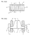
- FIG. 2(a) is a plan view of an example of a combined
product composed of pieces according to one embodiment of the
present invention and FIG. 2(b) is a sectional view taken on
line X-X of FIG. 2(a).
- FIG. 3 is a conceptual view showing a first step of
injection molding using the metal mold according to one
embodiment of the present invention.
- FIG. 4 is a conceptual view showing a second step of
injection molding using the metal mold according to one
embodiment of the present invention.
- FIG. 5 is a conceptual view showing a third step of
injection molding using the metal mold according to one
embodiment of the present invention.
- FIG. 6(a) is a conceptual view showing a first step of
injection molding using a modification of the metal mold
according to one embodiment of the present invention and 6(b)
is a conceptual view showing another modification of the
metal mold.
- FIG. 7 is a conceptual view showing a second step of
injection molding using a metal mold according to one
embodiment of the present invention.
- FIG. 8 is a conceptual view showing a first step of
injection molding using the metal mold according to another
embodiment of the present invention.
- FIG. 9 is a conceptual view showing a third step of
injection molding using the metal mold according to the
present invention.
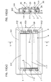
- FIG. 10(a) is a plan view of an example of a combined
product composed of pieces according to another embodiment of
the present invention and FIG. 10(b) is a sectional view
taken on line Y-Y of FIG. 10(a).
- FIG. 11 is a perspective view showing another example of
the combined product composed of pieces according to another
embodiment of the present invention.
- FIG. 12(a) is a conceptual view showing a first step of
injection molding a combined product composed of pieces
according to another embodiment of the present invention and
FIG. 12(b) is a conceptual view showing a second step.
- FIG. 13(a) is a conceptual view showing a modification
of a first step of injection molding a combined product
composed of pieces according to another embodiment of the
present invention and FIG. 13(b) is a conceptual view showing
a second step.
- FIG. 14 is a conceptual view showing a modification of
the metal mold according to another embodiment of the present
invention.
- FIG. 15(a) is a developed view of a conventional
combined product composed of pieces and FIG. 15(b) is a
sectional view of a hinge portion shown in FIG. 15(a).
-
DESCRIPTION OF THE PREFERRED EMBODIMENTS
-
Embodiments of a combined product composed of pieces, a
mold for the combined product, and a method of molding the
combined product will be described below. In the following
description, parts similar to those previously described in
the Background of the Invention are denoted by the same
reference numerals and are not shown in the drawings, and an
explanation will not be given thereto.
-
First, an outline of embodiments of the present
invention will be described. As shown in FIGs. 1(a) and 1(b),
a combined product P according to the present invention is
composed of a first molded piece 2 having an insertion hole 1
(e.g. bearing hole) and a second molded piece 4 having an
insertion portion (e.g. axis) 3 that is inserted into the
insertion hole 1.
-
A metal mold M for molding the aforementioned combined
product P comprises a first piece mold 5 for molding a first
molded piece 2, a second piece mold 6 for molding a second
molded piece 4, and a pin core 8 for molding an insertion
hole 1. The first piece mold 5, the second piece mold 6, and
a later-described piece mold 9 can be of any shape or can be
freely determined or selected. Therefore, in the drawings,
the first piece mold 5, the second piece mold 6, and the
later-described piece mold 9 do not assume a specific shape
of the combined product P, and the metal mold M dose not
limit the shape of the combined product P.
-
Generally, a method of molding the combined product P
comprises the steps of: injection molding the first molded
piece 2 from a first plastic resin A, as shown in FIG. 1(a);
removing a pin core 8 that is used for forming the insertion
hole 1 in the first molded piece 2 from the first molded
piece 2, as shown in FIG. 1(b); and injection molding the
second molded piece 4 from a second plastic resin B.
-
By removing the pin core 8 from the first molded piece 2
as described above, the second plastic resin B is also filled
in the insertion hole 1 of the first molded piece 2, as shown
in FIG. 1(b), in the step of injection molding the second
molded piece 4 from the second plastic resin B. In this way,
the insertion portion 3 is produced.
-
Further, when the second plastic resin B is cooled, a
space t is formed between the insertion hole 1 and the
insertion portion 3, as shown in FIG. 1(c). This is because
the first plastic resin A and the second plastic resin B have
a different mold shrinkage factor. As the second plastic
resin B has a higher mold shrinkage factor than the first
plastic resin A, the space t becomes wider.
-
In the step shown in FIG. 1(b), an end 80 of the pin
core 8 is flush with the right-side inner surface of the
first piece mold 5 by removing the whole pin core 8 from the
first piece mold 5. However, the second plastic resin B may
be filled in the second piece mold 6 with the end 80 of the
pin core 8 set inside the first piece mold 5.
-
Alternatively, the pin core 8 may be slid more to the
right than its position shown in FIG. 1(b). In this case, if
another piece mold 9 as illustrated by phantom line is formed
in such a position that the second piece mold 6 and the piece
mold 9 are symmetric with respect to the first piece mold 5,
the second plastic resin B is also filled in the piece mold 9.
In this way, pieces of various shapes can be integrally
molded on both side of the insertion portion 3. The piece
mold 9 belongs to the second piece mold 6.
-
Alternatively, in the step shown in FIG. 1(a), the
second piece mold 6 may be omitted. The pin core 8 may not
be completely passed through the first piece mold 5 as shown
in FIG. (a), but only a part of the pin core 8 may be
inserted into the first piece mold 5. In other words, the
end 80 of the pin core 8 is set inside the first piece mold 5.
-
In this case, when the first plastic resin A is injected
into the first piece mold 5, it enters to the edge of the end
80 placed inside the first piece mold 5. Therefore, the
insertion hole 1 does not become a through hole but a
horseshoe-shaped hole that is concave on the right side in
FIG. 1(a). When the second plastic resin B is filled in the
piece mold 9, a bit shorter insertion portion 3 is formed.
Viewed from the left side of the combined product P, the end
face of the insertion portion 3 is hidden behind the first
plastic resin A filled in the first piece mold 5.
-
Next, detailed construction of the aforementioned
embodiment will be described. An specific example of the
combined product P is an adjustable fin unit shown in FIGs.
2(a) and 2(b). The combined product P consists of a frame
body 10 that is provided to an air outlet of an automobile
and a plurality of fins 11 that is attached inside the frame
body 10. Both ends of the respective fins 11 are rotatably
joined to the frame body 10 as insertion portions 3.
-
The both ends of the fin 11 jut outward from the frame
body 10. For example, a knob portion 11a is formed on the
one end of the fin 11, a gear portion 11b is formed on the
other end of the fin 11, and a fin body 11c is formed between
the two insertion portions 3. The knob portion 11a is used
for changing the direction of the fin body 11c by turning it
with fingers. The gear portion 11b interlocks a plurality of
fin bodies 11c. A crank and a connected rod can be
substituted for the gear portion 11b.
-
FIGs. 3 to 5 are a plan view showing a main part of the
metal mold M for molding the combined product P and
conceptually show a part corresponding to a rotating portion
J1 shown in FIG. 2(a) and 2(b). The first piece mold 5 and
the second piece molds 6 and 9 are of any shape. The frame
body 10 and the fin 11 will be hereinafter described in
relation to the first molded piece 2 and the second molded
piece 4, respectively. The knob portion 11a, the gear
portion 11b, and the fin body 11c are bigger than an outer
diameter of the insertion portion 3 and will be hereinafter
referred to as main molded portions.
-
As shown in FIGs. 3 to 5, the metal mold M comprises a
first piece mold 5 for molding a first molded piece 2, a
plurality of second piece molds 6 and 9 for molding main
molded portions 11b and 11c of a second piece mold 4, and a
pin core that can be inserted into and removed from the first
piece mold 5 and the second piece mold 6. The pin core 8
passes through a portion 7 corresponding to an insertion hole
1 and an insertion portion 3, and can be slid in the
horizontal direction in FIGs. 3 to 5.
-
The combine product P is injection molded using the
metal mold M through the following steps (a) to (e).
-
Step (a): As shown in FIG. 3, the pin core 8 is inserted
into a portion 7 corresponding to the insertion hole 1 and
the insertion portion 3. In the metal mold M, a thin-walled
portion 12 is formed between the first molded piece 2 and the
second molded piece 4 so as to secure a space therebetween.
In this specification, the portion 7 corresponding to the
insertion hole 1 and the insertion portion 3 is a circular
through hole that passes through the thin-walled portion 12.
Therefore, the first piece mold 5 and the second piece molds
6 and 9 are connected through the portion 7 (through hole)
corresponding to the insertion hole 1 and the insertion
portion 3.
-
The pin core 8 is a kind of slide core. It can be slid
by a hydraulic cylinder or the like provided to the metal
mold M regardless of opening and closing motion of the metal
mold M. When the pin core 8 is inserted into the portion 7
corresponding to the insertion hole 1 and the insertion
portion 3, the first piece mold 5 and the second piece molds
6 and 9 are cut off by the pin core 8.
-
Step (b): The first molded piece 2 is molded by filling a
first plastic resin A in the first piece mold 5 under pressure.
In this step, the insertion portion 1 is formed by the pin
core8. As the first plastic resin A, ABS resin (acrylonitrile,
butadiene, styrene) can be suitably used, for example. A mold
shrinkage factor of such plastic resin is about 7/1000.
-
Step (c): As shown in FIG. 4, the pin core 8 is removed
from the portion 7 corresponding to the insertion hole 1 and
the insertion portion 3 by sliding it in the right direction
of the drawing. Thus, the second piece molds 6 and 9 are
connected through a hole formed between them. Although the
end 80 of the pin core 8 is flush with the inner surface of
the second piece mold 9 in this drawing, it may jut into the
second piece mold 9. Alternatively, the pin core 8 may be
slid in the right direction of the drawing.
-
Step (d): As shown in FIG. 5, the second molded piece 4
is molded by filling the second plastic resin B in the second
piece molds 6 and 9 under pressure. In this step, the second
plastic resin B is also filled in the insertion hole 1 of the
first molded piece 2 and thus the insertion portion 3 is
formed. As the second plastic resin B, polypropylene can be
suitably used, for example. A mold shrinkage factor of
polypropylene is about 16/1000.
-
In the aforementioned step (c), the pin core 8 may stay
in the portion 7 and then it is removed from the portion 7 by
sliding it in the right direction of the drawing by using an
injection pressure of the second plastic resin B. Unless the
second plastic resin B has a lower thermal melting
temperature or extremely higher thermal melting temperature
than the first plastic resin A, the fist plastic resin A does
not melt even if it touches the second plastic resin B in the
aforementioned step (d).
-
Step (e): After the completion of cooling of the first
plastic resin A and the second plastic resin B, the metal
mold M is opened and the combined product P is removed from
the metal mold M. Since a space is formed between the
insertion hole 1 of the first molded piece 2 and the second
molded piece 4 as described above, the first molded piece 2
and the second molded piece 4 are in sliding contact with
each other and rotate freely.
-
The first plastic resin A and the second plastic resin B
may be such resin as acryl, polycarbonate, polyethylene,
polystyrene, polyvinyl chloride, and polyamide , as far as it
can be used in the injection molding. Also, since an
injection molding press, overall construction of the metal
mold M, ejector pin for releasing the combined product P from
the metal mold M, and spool, runner, or gate for injecting
the first plastic resin A and the second plastic resin B into
the metal mold M may vary depending on the shape and size of
the first molded piece 2 and the second molded piece 4, they
are not shown in the drawings and are not described in this
specification.
-
Although only the rotating portion J1 shown in FIG. 2(b)
has been described above, it is desirable to form two
insertion holes 1 and the insertion portions 3 at the same
time, as shown in FIGs. 6(a), 6(b), and 7.
-
Specifically, as shown in FIG. 6(a), a single pin core 8
is inserted into two portions 7 corresponding to two
insertion holes 1 and two insertion portions 3 and then the
first plastic resin A is filled in the first piece mold 5
under pressure. Thus, the first molded piece 2, namely the
frame body 10, is formed. Further, the pin core 8 is slid in
the right direction of the drawing so as to connect the
second piece molds 6 and 9 as shown in FIG. 7 and the second
plastic resin B is filled in the second piece molds 6 and 9.
In this way, the second molded pieces 4, namely fins 11, are
formed.
-
The pin core 8 may be divided into two. For example, as
shown in FIG. 6(b), the aforementioned pin core 8 and another
pin core 8 that can be freely inserted into and ejected form
the left end L of the drawing may be provided so that such
pair of pin cores 8 can be slid in the horizontal direction
of the drawing in such a manner that they move close to or
away from each other. In this case, the metal mold can be
more compact than the mold that is used for forming two
insertion holes 1 by one pin core 8.
-
While the first piece mold 5 shown in FIGs. 6(a) and
6(b) has been described in correspondence with the first
molded piece 2, namely the frame body 10, the two piece molds
5 that are placed on the right and left sides in the drawing
may be a separate mold. In this case, the composed product P
is molded using three mold parts. Further, the number of the
first piece mold 5, the second piece mold 6, or the pin core
8 may be two, three, or more. As the numbers of the first
and the second piece molds 5 and 6 are increased, three or
more kinds of plastic resins may be used for filling them in
the first and the second piece molds 5 and 6.
-
It is not important whether or not the insertion portion
3 can actually rotate inside the insertion hole 1. The
insertion hole 1 and the insertion hole 3 may act as a
sliding joint which can freely slide in their axial
(longitudinal) direction. Therefore, the pin core 8 is not
necessarily circular in cross section, but it may be
polygonal or may have a key slot in cross section.
-
Further, the mold shrinkage factor of the first plastic
resin A may be higher than that of the second plastic resin B.
In this case, the insertion hole 1 and the insertion portion
3 are tightly fit and fixed to each other. Further, the
second plastic resin B and the first plastic resin A may be
the same material. Regardless of the mold shrinkage factor,
the first plastic resin A and the second plastic resin B may
be different in color so as to achieve colorful combined
product.
-
It should be understood that the present invention be
not limited to the aforementioned embodiments. Various
improvements, modifications, and variations can be made to
the embodiments on the basis of knowledge of the those
skilled in the art without departing from the scope of the
present invention.
-
Next, a combined product, a metal mold, and a method of
molding such combined product according to other embodiments
of the present invention will be described below. Parts
similar to those previously described are denoted by the same
reference numerals and will not be hereinafter shown in the
drawings and described.
-
It should be understood that the terms "first " and
"second" are used herein only for discriminating essential
components of the present invention and are not intended to
limit the essential components to two. For example, as shown
in FIGs. 8 and 9, an insertion hole 20 may be formed in the
second molded piece 4 using a pin core 18. This second
molded piece 4 having the insertion hole 20 is defined as a
new molded piece 1. Then a new second molded piece
(hereinafter referred to as a "third molded piece 14) having
an insertion portion 30 that is inserted into an insertion
portion 20 may be formed. Namely, a relation between a
second piece mold 6 and a third piece mold 16 is comparable
to a relation between the first piece mold 5 and the second
piece mold 6.
-
A metal mold M1 comprises a first piece mold 5, a second
piece mold 6, a pin core 8, a third piece mold 16 for molding
a third molded piece 14, and a pin core 18 for forming an
insertion portion 20 in the second molded piece 4 (second
plastic resin B).
-
Like the aforementioned molding method, a method of
molding a combined product P1 comprises the steps of:
injection molding a first molded piece 2; immediately after
that, removing a pin core 8 from the first molded piece 2;
and injection molding a second molded piece 4. In addition,
the method of molding a combined product P1 further comprises
the steps of: removing the pin core 18 that is used for
forming an insertion hole 20 in the second molded piece 4;
injecting a third plastic rein C into a third piece mold 16;
and cooling the third plastic resin C until it is hardened.
-
By removing the pin core 18 from the second molded piece
4 in the aforementioned manner, the third plastic resin C is
filled in the insertion hole 20 in the step of injection
molding the third molded piece 14 from the third plastic
resin C, and thus the insertion portion 30 of the third
molded piece 14 is formed. Further, when the third plastic
resin C is cooled, a space is formed between the insertion
hole 20 and the insertion portion 30. As described above,
this is caused by a difference in mold shrinkage factor.
-
A specific example of the combined product P1 is an
adjustable fin unit shown in FIG. 10(a). The combined
product P1 consists of a frame body 100 (corresponding to the
first molded piece 2) that is provided to an air outlet of an
automobile and a plurality of fins 111 (corresponding to the
second molded piece 4) that is attached inside the frame body
100. Both ends 112 of the respective fin 111 act as
insertion portions 3 and are rotatably attached to the frame
body 100. One of the ends 112 is a crank and the insertion
hole 20 is formed in this end 112.
-
Further, as shown in FIG. 10(b), the third molded piece
14 of the combined product P1 is a connecting rod. The third
molded piece 14 has the insertion portion 30 that is
rotatably inserted into the insertion hole 20 and that
interlocks the respective fins 111.
-
In the aforementioned embodiments, the insertion hole 20
is formed in the fin 111 and the insertion portion 30 is
formed on the connecting rod, namely the third molded piece
14. However, contrary to the above, if the connecting rod is
molded before molding the fins 111, the insertion portion 30
is formed on the fins 111 and the insertion hole 20 is formed
in the connecting rod. The counterchanging of the insertion
hole 20 and the insertion portion 30 in accordance with the
order of molding will be described later.
-
Another example of the aforementioned adjustable fin
unit is a combined product P2 as shown in FIG. 11. The
combined product P2 comprises: an outer frame body 200
(corresponding to the first molded piece 2) provided to an
air outlet of an air conditioner of an automobile; an inner
frame body 221 (corresponding to the second molded piece 4)
having a plurality of fins 211 that are integrally secured in
a horizontal position inside the frame body 200, and an
insertion portion 30 that is provided in a vertical position
inside the inner frame 221 and that is an axial substance on
which a plurality of fins 231 (corresponding to the third
molded piece 14) shown in FIG. 12(b) are integrally formed.
-
The insertion portion 3 juts from both ends 222 of the
inner frame body 221 and is supported by the insertion holes
1 formed in the outer frame body 200. The insertion portion
30 on which the fin 231 is integrally formed is rotatably
supported by the insertion holes 20 formed in the inner frame
body 221. A connecting rod for interlocking a plurality of
fins 231 may be injection molded as a fourth molded piece.
Alternatively, in order to avoid making the structure of the
metal mold M1 extremely complicated, a connected rod may be
provided after the combined product P2 is released from the
metal mold.
-
In FIGs. 11 and 12(a), numeral 201 indicates a through
hole from which the pin core 18 is removed and numeral 202
indicates a knob for rotating one of the insertion portions
30. The outer frame body 200 is inserted into an opening
that is provided beforehand to an installment panel of a car.
However, the installment panel itself may be the outer frame
body 200. In this case, the installment panel and the
combined product P2 can be continuously molded as the first
and the second molded pieces 2 and 4.
-
In the case of molding the combined product P2, the
insertion hole 1 is formed in the outer frame body 200 and
the insertion portion 3 is formed in the inner frame body 221.
This is because the outer frame body 200 is injection molded
first, as shown in FIG. 12(a), and then the inner frame body
221 is injection molded by pulling the pin core 18 in the
outer direction of the outer frame body 200 (pulling it in
the right direction of the drawing), as shown in FIG. 12(b).
Where the inner frame body 221 is injection molded first as
shown in FIG. 13(a), then the pin core 8 is pulled out to the
position shown in FIG. 13(b), and subsequently the outer
frame body 200 is injection molded, the insertion portion 3
is formed on the outer frame body 200 and the insertion hole
1 is formed in the inner frame body 221.
-
Further, as shown in FIG. 14, the pin core 8 may be a
sleeve core into which a needle core 28 having a shorter
inside diameter than the pin core 8 is inserted. In this
case, the insertion hole 1 of the second molded piece 4 and
the insertion hole 20 of the third molded piece 14 can be
different in diameter. Also, the pin core 8 and the needle
core 28 may be slid through a different distance.
Alternatively, in order to intentionally change the order of
injection molding the first to third molded pieces 2, 4 and
14, one of the pin core 8 and the needle core 28 may be slid
while the other stays.
-
As described above, in the metal mold for a combined
product composed of pieces and the method of molding such
composed product according to the present invention, a main
molded portion that has a larger outside diameter than the
insertion portion can be formed on one or both side(s) of the
insertion portion for a short time through simple steps in
which two injection molding steps are carried out in just one
action of opening and closing of the mold. Therefore, no
process is necessary after releasing the combined product
from the metal mold.
-
Since a quite narrow space whose width is some thousands
of millimeters of the inside diameter or outside diameter of
the insertion hole is formed between the insertion hole and
the insertion portion due to a difference in mold shrinkage
factor between the two kinds of resins, a play between the
insertion hole and the insertion portion can be minimized.
-
Therefore, a combined product composed of some molded
pieces can be produced in quantities for a short time using a
mold of a simple structure regardless of the accuracy and the
shape of a desired combined product.
-
When a mold shrinkage factor of a first resin is set
higher than that of a second resin, the insertion hole and
the insertion portion are tightly fit so that they can be
fixed to each other. By using different colors of resins as
the first and the second resins, a colorful combined product
can be achieved.
INDUSTRIAL APPLICABILITY
-
A metal mold for a combined product of some molded
pieces and a method of molding such combined product
according to the present invention are suitably used for
producing a combined product that can be obtained by
rotatably joining a first molded piece to a second molded
piece by pins, such as a spectacle case described above as an
example.
-
Further, where an installment panel or the like of a car
is molded, a main body of such installment panel and other
parts that are rotatably provided to the main body can be
molded in succession in just one action of opening and
closing of the mold. For example, in the case where an air
outlet of an air conditioner is formed in a dashboard of a
car and an adjustable fin unit is provided to this air outlet,
the dashboard itself and the adjustable fin unit can be
molded in succession in just one action of opening and
closing of the mold. Therefore, the production cost of the
car can be dramatically reduced.
-
Generally, in the case of a product having a pin joint
or a joint part, the pin joint or joint part is necessary to
be assembled. However, if the present invention is used for
producing such product having a pin joint or a joint part,
assembling of the product can be conducted at the same time
of the injection molding. Therefore, such combined product
can be produced quickly at a low cost.