EP1520568B1 - Wärmeaustauschvorrichtung, insbesondere zur Anwendung der Wärmebehandlung - Google Patents
Wärmeaustauschvorrichtung, insbesondere zur Anwendung der Wärmebehandlung Download PDFInfo
- Publication number
- EP1520568B1 EP1520568B1 EP03425646A EP03425646A EP1520568B1 EP 1520568 B1 EP1520568 B1 EP 1520568B1 EP 03425646 A EP03425646 A EP 03425646A EP 03425646 A EP03425646 A EP 03425646A EP 1520568 B1 EP1520568 B1 EP 1520568B1
- Authority
- EP
- European Patent Office
- Prior art keywords
- thermal
- exchange apparatus
- carrier fluid
- thermal exchange
- primary
- Prior art date
- Legal status (The legal status is an assumption and is not a legal conclusion. Google has not performed a legal analysis and makes no representation as to the accuracy of the status listed.)
- Expired - Lifetime
Links
- 238000007669 thermal treatment Methods 0.000 title abstract description 28
- 239000012530 fluid Substances 0.000 claims abstract description 76
- 230000008859 change Effects 0.000 claims abstract description 10
- 239000000463 material Substances 0.000 claims description 13
- XLYOFNOQVPJJNP-UHFFFAOYSA-N water Substances O XLYOFNOQVPJJNP-UHFFFAOYSA-N 0.000 claims description 9
- 239000002826 coolant Substances 0.000 claims description 8
- 239000004800 polyvinyl chloride Substances 0.000 claims description 3
- 230000009969 flowable effect Effects 0.000 claims description 2
- 229920000915 polyvinyl chloride Polymers 0.000 claims 1
- 241001465754 Metazoa Species 0.000 abstract description 7
- 238000004519 manufacturing process Methods 0.000 description 7
- 238000011282 treatment Methods 0.000 description 6
- 230000008901 benefit Effects 0.000 description 5
- 241000283086 Equidae Species 0.000 description 4
- 230000009471 action Effects 0.000 description 4
- 230000007423 decrease Effects 0.000 description 4
- 238000010586 diagram Methods 0.000 description 4
- 239000000126 substance Substances 0.000 description 4
- 230000007170 pathology Effects 0.000 description 3
- 230000001225 therapeutic effect Effects 0.000 description 3
- 238000006243 chemical reaction Methods 0.000 description 2
- 238000001816 cooling Methods 0.000 description 2
- 238000010438 heat treatment Methods 0.000 description 2
- 230000002035 prolonged effect Effects 0.000 description 2
- 238000007789 sealing Methods 0.000 description 2
- 208000022052 Bilateral acute depigmentation of the iris Diseases 0.000 description 1
- 206010018852 Haematoma Diseases 0.000 description 1
- 206010028331 Muscle rupture Diseases 0.000 description 1
- 208000010040 Sprains and Strains Diseases 0.000 description 1
- 239000002671 adjuvant Substances 0.000 description 1
- 238000005273 aeration Methods 0.000 description 1
- 230000000386 athletic effect Effects 0.000 description 1
- 230000009286 beneficial effect Effects 0.000 description 1
- 208000006111 contracture Diseases 0.000 description 1
- 230000003247 decreasing effect Effects 0.000 description 1
- 230000008030 elimination Effects 0.000 description 1
- 238000003379 elimination reaction Methods 0.000 description 1
- 239000004744 fabric Substances 0.000 description 1
- 238000007710 freezing Methods 0.000 description 1
- 230000008014 freezing Effects 0.000 description 1
- 230000035876 healing Effects 0.000 description 1
- 230000002631 hypothermal effect Effects 0.000 description 1
- 230000006872 improvement Effects 0.000 description 1
- 239000012535 impurity Substances 0.000 description 1
- 208000014674 injury Diseases 0.000 description 1
- 238000009413 insulation Methods 0.000 description 1
- 210000003205 muscle Anatomy 0.000 description 1
- 238000005192 partition Methods 0.000 description 1
- 230000002265 prevention Effects 0.000 description 1
- 230000000087 stabilizing effect Effects 0.000 description 1
- 239000013589 supplement Substances 0.000 description 1
- 238000002560 therapeutic procedure Methods 0.000 description 1
- 230000008733 trauma Effects 0.000 description 1
Images


Classifications
-
- A—HUMAN NECESSITIES
- A61—MEDICAL OR VETERINARY SCIENCE; HYGIENE
- A61F—FILTERS IMPLANTABLE INTO BLOOD VESSELS; PROSTHESES; DEVICES PROVIDING PATENCY TO, OR PREVENTING COLLAPSING OF, TUBULAR STRUCTURES OF THE BODY, e.g. STENTS; ORTHOPAEDIC, NURSING OR CONTRACEPTIVE DEVICES; FOMENTATION; TREATMENT OR PROTECTION OF EYES OR EARS; BANDAGES, DRESSINGS OR ABSORBENT PADS; FIRST-AID KITS
- A61F7/00—Heating or cooling appliances for medical or therapeutic treatment of the human body
- A61F7/02—Compresses or poultices for effecting heating or cooling
-
- A—HUMAN NECESSITIES
- A61—MEDICAL OR VETERINARY SCIENCE; HYGIENE
- A61F—FILTERS IMPLANTABLE INTO BLOOD VESSELS; PROSTHESES; DEVICES PROVIDING PATENCY TO, OR PREVENTING COLLAPSING OF, TUBULAR STRUCTURES OF THE BODY, e.g. STENTS; ORTHOPAEDIC, NURSING OR CONTRACEPTIVE DEVICES; FOMENTATION; TREATMENT OR PROTECTION OF EYES OR EARS; BANDAGES, DRESSINGS OR ABSORBENT PADS; FIRST-AID KITS
- A61F7/00—Heating or cooling appliances for medical or therapeutic treatment of the human body
- A61F2007/0001—Body part
-
- A—HUMAN NECESSITIES
- A61—MEDICAL OR VETERINARY SCIENCE; HYGIENE
- A61F—FILTERS IMPLANTABLE INTO BLOOD VESSELS; PROSTHESES; DEVICES PROVIDING PATENCY TO, OR PREVENTING COLLAPSING OF, TUBULAR STRUCTURES OF THE BODY, e.g. STENTS; ORTHOPAEDIC, NURSING OR CONTRACEPTIVE DEVICES; FOMENTATION; TREATMENT OR PROTECTION OF EYES OR EARS; BANDAGES, DRESSINGS OR ABSORBENT PADS; FIRST-AID KITS
- A61F7/00—Heating or cooling appliances for medical or therapeutic treatment of the human body
- A61F2007/0054—Heating or cooling appliances for medical or therapeutic treatment of the human body with a closed fluid circuit, e.g. hot water
-
- A—HUMAN NECESSITIES
- A61—MEDICAL OR VETERINARY SCIENCE; HYGIENE
- A61F—FILTERS IMPLANTABLE INTO BLOOD VESSELS; PROSTHESES; DEVICES PROVIDING PATENCY TO, OR PREVENTING COLLAPSING OF, TUBULAR STRUCTURES OF THE BODY, e.g. STENTS; ORTHOPAEDIC, NURSING OR CONTRACEPTIVE DEVICES; FOMENTATION; TREATMENT OR PROTECTION OF EYES OR EARS; BANDAGES, DRESSINGS OR ABSORBENT PADS; FIRST-AID KITS
- A61F7/00—Heating or cooling appliances for medical or therapeutic treatment of the human body
- A61F7/007—Heating or cooling appliances for medical or therapeutic treatment of the human body characterised by electric heating
- A61F2007/0077—Details of power supply
- A61F2007/0078—Details of power supply with a battery
-
- A—HUMAN NECESSITIES
- A61—MEDICAL OR VETERINARY SCIENCE; HYGIENE
- A61F—FILTERS IMPLANTABLE INTO BLOOD VESSELS; PROSTHESES; DEVICES PROVIDING PATENCY TO, OR PREVENTING COLLAPSING OF, TUBULAR STRUCTURES OF THE BODY, e.g. STENTS; ORTHOPAEDIC, NURSING OR CONTRACEPTIVE DEVICES; FOMENTATION; TREATMENT OR PROTECTION OF EYES OR EARS; BANDAGES, DRESSINGS OR ABSORBENT PADS; FIRST-AID KITS
- A61F7/00—Heating or cooling appliances for medical or therapeutic treatment of the human body
- A61F7/0085—Devices for generating hot or cold treatment fluids
Definitions
- the present invention refers to a thermal exchange apparatus, which has preferred although not exclusive use as apparatus for localised application of thermal treatments to body parts of living beings, particularly animals or people, even more particularly to horses.
- thermal therapy in the treatment of various types of traumas or pathologies are known, both to alleviate pain and as adjuvant for the healing process.
- application of thermal treatments to human or animal body parts is also useful, in particular in the sport field, to tone up muscle or joints in anticipation of or after prolonged or intense physical effort, in order to avoid harmful contractures.
- thermal treatments cited above are particularly appreciated for horses, above all for treating and preventing pathologies involving limbs, such as, for example, haematomas, sprains, torn muscles; they are also validly used to relieve and tone up the limbs of horses which must bear prolonged or intense stresses in athletic competitions.
- ice For the application of cold, ice is commonly used. This system is easy and quick to use, but has the drawback of being able to keep the desired cold for a limited time, making frequent replacements necessary if the duration of the treatment goes on for a long time. Moreover, there is the need to have freezer units, not always available for outdoor applications, like, for example, in horse stables.
- Bags containing coolants or substances which perform a refrigerating action as a consequence of endothermic chemical reactions are also used; the use of such bags allows the cold to be maintained for a longer time, but has a series of drawbacks. Bags containing coolants can be used many times over, however their use is laborious due to the need of having freezing units to cool down the bags with the coolant and keep them at a low temperature until the time of application. Bags containing substances which perform a refrigerating action as a consequence of endothermic chemical reactions are easier to use, with respect to the previous ones, but can each be used just once, because such substances lose their refrigerating capability after the first use. Both such substances and the coolants cited above are, however, more expensive and more difficult to obtain with respect to ice.
- a hypothermia device is also known from US 2726658 .
- electrical resistance devices are also used, which make use of the heat generated by one or more resistances flown by electric current.
- Such devices allow a more accurate temperature control and allow also long treatments, but require the availability of a power supply, and that devices flown by electric current are brought into direct contact with the body, with potential safety problems.
- Such a device although simple and cost-effective, necessarily requires connection to a waterworks or another water source, and in any case has the aforementioned drawback of reduced possibility of fine adjustment of the temperature of the treatment; moreover, it is not always desirable for the part to be treated to be constantly wetted by water that flows out from the micropores.
- the technical problem at the basis of the present invention is therefore to provide a thermal exchange apparatus, particularly for the application of localised thermal treatments, which overcomes the drawbacks cited above with reference to the prior art, in particular as far as the flexibility and ease of use are concerned.
- the invention is defined in claim 1. It relates to a thermal exchange apparatus comprising a primary circuit for circulating a primary thermal carrier fluid, said primary circuit being enclosed in a main body and comprising at least one compressor, means for imposing a temperature change on said primary thermal carrier fluid, an expansion member for said primary thermal carrier fluid and a first heat exchanger, at which said primary thermal carrier fluid undergoes a temperature change opposite in sign, characterised in that a secondary circuit for circulating a secondary thermal carrier fluid is thermally coupled with said primary circuit at said first heat exchanger, said secondary circuit comprising at least one second heat exchanger between said secondary thermal carrier fluid and an external body, said second heat exchanger being external to said main body.
- the primary circuit embodies a thermal cycle for producing cold or heat
- thanks to the use of said secondary circuit and of said at least one second heat exchanger it is possible to easily transfer the cold and/or heat to the outside of said main body of the apparatus and apply it to an external body, even at a distance from such a main body.
- a substantial flexibility and ease of use of the apparatus is overall attained.
- said at least one second heat exchanger comprises a bag made of flexible material, flowable by said secondary thermal carrier fluid. This advantageously allows providing an exchanger adaptable to the part to be thermally treated, so as to ensure a correct and comfortable application thereof.
- Said flexible material is preferably polyvinyl chloride (PVC), a material having an advantageous balance between strength and flexibility.
- PVC polyvinyl chloride
- said bag comprises a zig-zagging path obtained through heat-sealing of portions of the walls of said bag.
- a zig-zagging path for the secondary thermal carrier fluid allows the thermal exchange between such a fluid and said external body to be improved, for a better and more uniform application of the thermal treatment.
- a support sack having means for removably fastening to said external body is removably associated with said bag.
- said bag can be produced according to a standard size and shape, whereas said support sack can have different shapes to better adapt to said external body or parts thereof; it is thus possible to associate the same bag each time with different support sacks according to the application.
- the use of a removable support sack also allows greater hygiene of use.
- said support sack is made of flexible material.
- said removable fastening means is adjustable.
- Both of the provisions allow better adaptability to said external body, or parts thereof, of said support sack, which can also thus be produced according to standard shapes and sizes and subsequently adapted at the time of application.
- preferred removable fastening means comprise hooks and loops systems (VelcroTM), buckles or strings, possibly elastic.
- said support sack comprises a thermally insulating main surface; such a thermally insulating surface advantageously ensures the thermal insulation of said bag towards the external environment when inserted in said support sack for a thermal treatment, so as to increase the overall thermal efficiency of the apparatus.
- said support sack also comprises a main surface made of anti-allergenic material; the presence of such a surface is particularly advantageous when the thermal treatment is to be applied to an animal or human body.
- said at least one second heat exchanger is connected to said main body through flexible tubular ducts; this aspect advantageously allows said at least one second exchanger to be freely moved to bring it at said external body, possibly even at a distance from the main body of the thermal exchange apparatus. This gives further flexibility and ease of use to the apparatus as a whole, allowing in particular a certain freedom of movement for a living being receiving the thermal treatment.
- said flexible tubular ducts are thermally insulated, so as to be able to keep said secondary thermal carrier fluid at the temperature required by the thermal treatment, with a consequent improvement of the overall efficiency of the apparatus.
- tubular ducts are removably connected to said main body and/or to said at least one second heat exchanger.
- said tubular ducts are removably connected to said main body and/or to said at least one second heat exchanger.
- said primary circuit comprises means for switching between a first operating mode for producing cold at said external body and a second operating mode for producing heat at said external body; this feature offers the notable advantage of allowing the same thermal exchange apparatus to be used to administer cold or heat separately, and/or heat and cold alternately.
- said switching means comprises a four-way valve; advantageously, such a valve embodies a simple device for modifying the path of said primary thermal carrier fluid in said primary circuit and reversing the thermal cycle.
- a valve embodies a simple device for modifying the path of said primary thermal carrier fluid in said primary circuit and reversing the thermal cycle.
- said means for imposing a temperature change on said primary thermal carrier fluid comprises an air heat exchanger; advantageously, said heat exchanger allows the air of the external environment, which is always available, to be exploited as a heat source or well, respectively in the first or in the second operating mode defined above, to change the temperature of said primary thermal carrier fluid.
- Said secondary circuit can further comprise a selectively actuable electroheating element.
- Said selectively actuable electroheating element can advantageously be used to supplement the heat supplied to said secondary fluid from the primary thermal carrier fluid in said second operating mode (production of heat).
- Said expansion member of said primary circuit can be a capillary or else a thermostat valve. Both devices are suitable for operating in said first and second operating modes.
- a capillary has the advantage of being a particularly simple device, without moving members and therefore with reduced chances of failure and wear; a thermostat valve can, on the other hand, be advantageous in the case where higher thermal powers have to be processed.
- Said primary thermal carrier fluid is a coolant, for example Freon R134A and/or R404A.
- the secondary thermal carrier fluid is instead preferably water, which has the advantage of being commonly available at virtually zero cost and of not being a dangerous or harmful fluid. Its use in the secondary circuit is satisfactory, considering in particular the moderate performance required in the operating mode for producing cold.
- Said secondary circuit preferably comprises a pump for forcedly circulating said secondary thermal carrier fluid; this advantageously allows said secondary thermal carrier fluid to be circulated without restrictions on the configuration or length of said secondary circuit.
- the thermal exchange apparatus further comprises means for controlling and adjusting the thermal exchange between said secondary thermal carrier fluid and said external body, in order to advantageously be able to precisely control and adjust the parameters, in particular duration and temperature, under which said heat exchange is accomplished.
- Said control and adjustment means preferably comprises a timer, a mode selector and/or a programmable electronic control unit, which allow the duration and/or the type (cold, heat and/or alternating cold and heat, in all cases with predeterminable temperatures) of the thermal treatments to be set, through setting by the user and/or through preset cycles.
- the thermal exchange apparatus according to the present invention is preferably supplied with alternating current, to be able to be connected to a common electrical mains.
- it can also comprise a power supply battery; this feature advantageously allows said apparatus to be made autonomous as far as the electric power supply is concerned, making its portability easier.
- the main body of the thermal exchange apparatus of the invention is portable.
- the apparatus is therefore not forced to remain in a particular environment, but can be moved according to the need, even outdoors, with a further advantageous flexibility of use.
- a thermal exchange apparatus 1 essentially comprises: a main body 2, two bags 4, 4' for the application of thermal treatments to an external body (not shown in the figures) and two pairs of flexible and thermally insulated tubular ducts 3, 3'.
- the pairs of ducts 3, 3' connect the bags 4, 4' with the main body 2, ensuring that they are connected to a secondary circuit for circulating a secondary thermal carrier fluid (as illustrated in greater detail hereafter) having a given temperature, defined according to the type of thermal treatment to be applied on said external body.
- the bags 4, 4' are made of flexible material, preferably polyvinyl chloride (PVC), to be easily adapted to the configuration of the external body to which the thermal treatment is intended to be applied, or to parts thereof.
- PVC polyvinyl chloride
- the zig-zagging path 41 terminates at inlet and outlet fittings 43a of the secondary thermal carrier fluid, suitable for connecting with a respective connector 43b, provided at the end of the ducts 3, 3'.
- the zig-zagging path 41 can be obtained by suitably deforming a flexible tubular duct, which can then be fixed inside the bags 4, 4' so as to keep the shape given to it and to be easier to apply. It is also possible to make bags 4, 4' without any path inside, with the advantage of greater simplicity of manufacture and, consequently, of greater cost-effectiveness, without departing from the scope of protection of the present invention.
- the bags 4, 4' are removably associated each with a support sack 5, as shown in figure 2 .
- a support sack also made of flexible material, comprises a main surface 51 and an opposite main surface 52, between which a pocket 55 is defined, suitable to receive a respective bag 4, 4'.
- the sack 5 further comprises means 54 to allow it to be removably fixed to the external body for which it is intended, or to part thereof.
- Such means comprises a pair of elements of a hooks and loops system (VelcroTM) on a first surface of closing wings 53 and a corresponding pair of such elements on the opposite main surface 52 of the sack 5 (of which just one is visible in figure 2 ).
- the removable fastening means 54 may comprise a plurality of buckles or strings, possibly elastic.
- the main surface 51 is made of anti-allergenic material, whereas the opposite main surface 52 is thermally insulating.
- the main surface 51 made of anti-allergenic material is brought into contact with the body, whereas the opposite thermally insulating main surface 52 is left outwards, so that the fluid circulating in the bag 4, 4' preferentially exchanges heat with the body, while remaining thermally insulated with respect to the rest of the external environment.
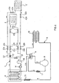
- the main body 2 of the thermal exchange apparatus 1 houses within it a plurality of devices forming part of the primary circuit 6, mounted on a support base 20, in particular: a compressor 8; a four-way valve 9 electrically controlled by means of a solenoid (not shown); an air exchanger 10, with a fan 15 and a collector 16 associated; a filter 17, having the function of holding impurities and possible humidity present inside the primary circuit, and a first heat exchanger 11 at which thermal exchange takes place between a primary thermal carrier fluid and the secondary thermal carrier fluid.
- the heat exchanger 11 is a concentric tube exchanger and comprises an outer tubular duct and an inner tubular duct.
- the primary thermal carrier fluid flows in the inner tube, whereas the secondary thermal carrier fluid flows in the gap between inner tube and outer tube.
- the heat exchanger 11 is shaped so as to be able to be housed in a volume 19, defined between the support base 20 and a base 21 of the main body 2.
- the bases 20, 21 are internally insulated, so as to thermally insulate the heat exchanger 11 with respect to the external environment.
- the primary circuit 6 further comprises an expansion member 13 (shown for clarity only in the block diagrams of figure 4 and 5 ), which is typically a capillary. Alternatively, in the case where high thermal powers are present, the use of a thermostat valve can be foreseen.
- the main body 2 also houses some of the devices of the secondary circuit 7, in particular, besides the first heat exchanger 11 just described above and shared with the primary circuit 6: a pump 14, with a relative support 31, for circulating the secondary thermal carrier fluid; a storage tank 18 for the secondary thermal carrier fluid with relative support 32; a selectively actuable electroheating element 12; two pairs of rapid fastening/releasing connectors 22, with relative male 22a and female 22b elements, for example of the bayonet type, for the connection of the flexible tubular ducts 3, 3' with the main body 2, and a collar 33, with relative supporting upright 23, for mounting the attachments 22.
- a pump 14 with a relative support 31, for circulating the secondary thermal carrier fluid
- a storage tank 18 for the secondary thermal carrier fluid with relative support 32
- a selectively actuable electroheating element 12 two pairs of rapid fastening/releasing connectors 22, with relative male 22a and female 22b elements, for example of the bayonet type, for the connection of the flexible tubular ducts 3, 3' with the main
- main body 2 there are also electric power supply devices, only schematically illustrated under reference numeral 36 in figure 3 , including a power supply transformer to convert mains alternating current into low direct supply voltage, for example 12V.
- a power supply transformer to convert mains alternating current into low direct supply voltage, for example 12V.
- thermo exchange apparatus 1 In addition or as an alternative to mains power supply, it is possible to foresee the use of a battery (not shown in the figures), preferably rechargeable, to make the thermal exchange apparatus 1 not reliant upon an external power supply.
- a battery not shown in the figures
- Adjustment and control devices comprising a programmable electronic control unit 24, an operating mode (cold/heat) selector 34 and a timer 26, and a general switch 25 are housed in the main body 2 and accessible from the outside.
- a casing 27 which is removably associated with the base 21.
- a casing 27 is equipped with grip means 28 for transporting the main body 2, and with a removable front panel 29 equipped with an aeration grid 29 for the air exchanger 10, and with slots for the access to the aforementioned adjustment and control devices 24-26, 34.
- the four-way valve 9 is in a first operating configuration, through which the delivery of the compressor 8 is connected with the air exchanger 10 and its suction with the first heat exchanger 11, through the filter 17.
- the primary thermal carrier fluid which has previously been compressed by the compressor 8, undergoes a temperature decrease, transferring a first amount of heat to the external environment.
- the primary thermal carrier fluid then reaches the expansion capillary 13, within which it expands, and then the first heat exchanger 11, at which it undergoes a temperature increase, absorbing a second amount of heat from the secondary thermal carrier fluid.
- the primary thermal carrier fluid finally returns, through the four-way valve 9 and the filter 17, to the suction of the compressor 8.
- the secondary thermal carrier fluid is circulated in the secondary circuit 7 through the circulation pump 14. It decreases its temperature at the first heat exchanger 11, transferring the aforementioned second amount of heat to the primary thermal carrier fluid, and therefore cooling down, and then reaches at the bags 4, 4', having the function of second heat exchangers, at the desired temperature (cold) for the thermal treatment on the external body, on which such bags have previously been applied.
- the secondary thermal carrier fluid takes away heat from the external body, cooling it down.
- the secondary thermal carrier fluid finally returns, after having passed through the tank 18 and the pump 14, to the first heat exchanger 11 to transfer the heat absorbed from the external body to the primary thermal carrier fluid, once again decreasing its own temperature.
- the electroheating element 12 is not active, as schematically represented by the switch 121 in the open position.
- a by-pass valve 35 (shown only in the block diagrams of figure 4 and 5 ) is also preferably provided so as to allow sending part of the flow rate of secondary thermal carrier fluid directly to the tank 18 without making it flow through the bags 4, 4', in the case where it detects overpressures in the secondary circuit, in order to protect the bags 4, 4' from such overpressures which could damage them or, in the worst case, make them burst.
- the four-way valve 9 is in a second operating configuration, through which the suction of the compressor 8 is connected with the air exchanger 10, through the filter 17, and its delivery is connected with the first heat exchanger 11.
- the primary thermal carrier fluid undergoes a temperature increase, receiving a first amount of heat from the external environment.
- the primary thermal carrier fluid through the four-way valve 9 and the filter 17, reaches the compressor 8, where it is compressed, and then, again through the four-way valve 9, the first heat exchanger 11, at which it undergoes a temperature decrease, transferring a second amount of heat to the secondary thermal carrier fluid.
- the primary thermal carrier fluid finally returns, after having expanded through the expansion capillary 13, to the air exchanger 10.
- the secondary thermal carrier fluid circulated in the secondary circuit 7 through the circulation pump 14, increases its temperature at the first heat exchanger 11, receiving the aforementioned second amount of heat from the primary thermal carrier fluid.
- Such a second amount of heat can also be increased (for example, when the temperature of the external environment is too low, as it could happen in the winter months) through the heating obtained through the actuation of the electroheating element 12.
- This condition is schematically represented in figure 5 by the switch 121 of the power supply circuit in closed position.
- the secondary thermal carrier fluid then reaches the bags 4, 4', at the desired temperature (hot) for the thermal treatment on the external body, on which such bags have previously been applied.
- the secondary thermal carrier fluid transfers heat to the external body, heating it up, and undergoing a temperature decrease.
- the secondary thermal carrier fluid finally returns, after having passed through the tank 18 and the pump 14, to the first heat exchanger 11 to receive from the primary thermal carrier fluid the heat previously transferred to the external body and once again increase its own temperature.
- the switching between the two operating modes, based upon the type of thermal treatment to be applied, can be carried out manually by a user, possibly with the aid of the operating mode (cold/heat) selector 34 and the timer 26, or else can take place automatically, under the control of the programmable electronic control unit 24.
- a programmable electronic control unit 24 in carrying out the control, operatively interacts with devices for controlling the temperature of the primary thermal carrier fluid (not shown in the figures), in particular a thermostat and temperature sensors, and with actuators (not shown in the figures) acting upon the devices of the primary circuit 6 and secondary circuit 7, in particular on the four-way valve 9 and on the power supply circuit for the electroheater 12.
- the thermal exchange apparatus 1 has a preferred use for the application of localised thermal treatments to parts of the body of living beings. Such localised thermal treatments are preferably therapeutic'treatments.
- the thermal exchange apparatus 1 is used for the application of thermal treatments to horses, in particular for the treatment or prevention of pathologies or fatigue of the limbs. It is therefore advantageous to have an apparatus equipped with a plurality of second heat exchangers, such as bags 4, 4', for carrying out a thermal treatment on many limbs simultaneously.
- a plurality of second heat exchangers such as bags 4, 4'
- the present detailed description has been made with reference to an embodiment comprising two second heat exchangers 4, 4' for the application of a thermal treatment, but it is manifest that an embodiment comprising many second heat exchangers (for example four, to treat the four legs of a horse simultaneously), or else even a single second heat exchanger, fully falls within the scope of the present invention.
- bag(s) 4, 4' can be unremovably fixed in the secondary circuit 7.
Landscapes
- Health & Medical Sciences (AREA)
- Vascular Medicine (AREA)
- Thermal Sciences (AREA)
- Engineering & Computer Science (AREA)
- Biomedical Technology (AREA)
- Heart & Thoracic Surgery (AREA)
- Physics & Mathematics (AREA)
- Life Sciences & Earth Sciences (AREA)
- Animal Behavior & Ethology (AREA)
- General Health & Medical Sciences (AREA)
- Public Health (AREA)
- Veterinary Medicine (AREA)
- Thermotherapy And Cooling Therapy Devices (AREA)
Claims (24)
- Wärmeaustauschvorrichtung (1), umfassend:- eine primäre Schaltung (6) zum Umwälzen eines primären Wärmeträgerfluides, wobei die primäre Schaltung in einem Hauptkörper (2) eingeschlossen ist und wenigstens einen Kompressor (8), Mittel (10) zum Bewirken einer Temperaturänderung an dem primären Wärmeträgerfluid, ein Expansionsglied (13) für das primäre Wärmeträgerfluid und einen ersten Wärmetauscher (11), an dem das primäre Wärmeträgerfluid eine dem Vorzeichen nach entgegengesetzte Temperaturänderung erfährt, umfasst und- eine geschlossene sekundäre Schaltung (7) zum Umwälzen eines sekundären Wärmeträgerfluides, das thermisch mit der primären Schaltung an dem ersten Wärmetauscher (11) gekoppelt ist, wobei die sekundäre Schaltung umfasst:a) wenigstens einen zweiten Wärmetauscher (4, 4') zwischen dem sekundären Wärmeträgerfluid und einem äußeren Körper, wobei der zweite Wärmetauscher (4, 4') außerhalb des Hauptkörpers (2) befindlich ist; undb) einen Speichertank (18) für das sekundäre Wärmeträgerfluid;dadurch gekennzeichnet, dass die sekundäre Schaltung (7) des Weiteren ein Bypassventil (35) umfasst, das für den Fall, dass es Überdrücke in der sekundären Schaltung erfasst, dafür ausgelegt ist zu ermöglichen, einen Teil der Flussrate des sekundären Wärmeträgerfluides an den Speichertank (18) zu senden, ohne dass es zuließe, dass dieses durch den zweiten Wärmetauscher (4, 4') fließen würde.
- Wärmeaustauschvorrichtung (1) nach Anspruch 1, wobei der wenigstens eine zweite Wärmetauscher einen Beutel (4, 4') umfasst, der aus einem flexiblen Material besteht, wobei der Beutel von dem sekundären Wärmeträgerfluid durchfließbar (41) ist.
- Wärmeaustauschvorrichtung (1) nach Anspruch 2, wobei das flexible Material Polyvinyl-chlorid ist.
- Wärmeaustauschvorrichtung (1) nach Anspruch 2 oder 3, wobei der Beutel (4, 4') einen Zickzackweg (41) zwischen wärmeabgedichteten Abschnitten (42) der Wände des Beutels (4, 4') umfasst.
- Wärmeaustauschvorrichtung (1) nach einem der Ansprüche 2 bis 4, wobei ein Hal-tesack (5) mit Mitteln (54) zum entfernbaren Befestigen an dem äußeren Körper dem Beutel (4, 4') entfernbar zugeordnet ist.
- Wärmeaustauschvorrichtung (1) nach Anspruch 5, wobei der Haltesack (5) aus einem flexiblen Material besteht.
- Wärmeaustauschvorrichtung (1) nach Anspruch 5 oder 6, wobei das entfernbare Befestigungsmittel (54) anpassbar ist.
- Wärmeaustauschvorrichtung (1) nach einem der Ansprüche 5 bis 7, wobei der Hal-tesack (5) eine thermisch isolierende Hauptoberfläche (52) umfasst.
- Wärmeaustauschvorrichtung (1) nach einem der Ansprüche 5 bis 8, wobei der Hal-tesack (5) eine Hauptoberfläche (51) umfasst, die aus einem antiallergenen Material be-steht.
- Wärmeaustauschvorrichtung (1) nach einem der vorhergehenden Ansprüche, wobei der wenigstens eine zweite Wärmetauscher (4, 4') mit dem Hauptkörper (2) durch flexible rohrförmige Kanäle (3, 3') verbunden ist.
- Wärmeaustauschvorrichtung (1) nach Anspruch 10, wobei die flexiblen rohrförmigen Kanäle (3, 3') thermisch isoliert sind.
- Wärmeaustauschvorrichtung (1) nach Anspruch 10, wobei die flexiblen rohrförmigen Kanäle (3, 3') entfernbar mit dem Hauptkörper (2) und/oder mit dem wenigstens einen zweiten Wärmetauscher (4, 4') verbunden sind.
- Wärmeaustauschvorrichtung (1) nach einem der vorhergehenden Ansprüche, wobei die primäre Schaltung (6) des Weiteren Mittel (9) zum Umstellen zwischen einem ersten Betriebsmodus zum Erzeugen von Kälte an dem äußeren Körper und einem zweiten Betriebsmodus zum Erzeugen von Wärme an dem äußeren Körper umfasst.
- Wärmeaustauschvorrichtung (1) nach Anspruch 13, wobei das Umstellmittel ein Vierwegeventil (9) umfasst.
- Wärmeaustauschvorrichtung (1) nach einem der vorhergehenden Ansprüche, wobei das Mittel (10) zum Bewirken einer Temperaturänderung an dem primären Wärmeträgerfluid einen Luftwärmetauscher (10) umfasst.
- Wärmeaustauschvorrichtung (1) nach einem der vorhergehenden Ansprüche, wobei die sekundäre Schaltung (7) des Weiteren ein selektiv betätigbares Elektroheizelement (12) umfasst.
- Wärmeaustauschvorrichtung (1) nach einem der vorhergehenden Ansprüche, wobei das Expansionsglied (13) der primären Schaltung unter einem Kapillar- und einem Thermostatventil ausgewählt ist.
- Wärmeaustauschvorrichtung (1) nach einem der vorhergehenden Ansprüche, wobei das primäre Wärmeträgerfluid und das sekundäre Wärmeträgerfluid ein Kühlmittel beziehungsweise Wasser sind.
- Wärmetauschvorrichtung (1) nach einem der vorhergehenden Ansprüche, wobei die sekundäre Schaltung (7) eine Pumpe (14) zum erzwungenen Umwälzen des zweiten Wärmeträgerfluides umfasst.
- Wärmeaustauschvorrichtung (1) nach einem der vorhergehenden Ansprüche, des Weiteren umfassend Mittel (24-26, 34) zum Steuern bzw. Regeln und Anpassen des Wärmeaustausches zwischen dem sekundären Wärmeträgerfluid und dem äußeren Körper.
- Wärmeaustauschvorrichtung (1) nach Anspruch 20, wobei das Steuer- bzw. Regel- und Anpassmittel (24-26, 34) einen Zeitgeber (26), einen Modusauswähler (34) und/oder eine programmierbare elektronische Steuer- bzw. Regeleinheit (24) umfasst.
- Wärmeaustauschvorrichtung (1) nach einem der vorhergehenden Ansprüche, die mit Wechselstrom betrieben wird.
- Wärmeaustauschvorrichtung nach einem der vorhergehenden Ansprüche, die eine Energieversorgungsbatterie umfasst.
- Wärmeaustauschvorrichtung (1) nach einem der vorhergehenden Ansprüche, wobei der Hauptkörper (2) tragbar ist.
Priority Applications (5)
| Application Number | Priority Date | Filing Date | Title |
|---|---|---|---|
| EP03425646A EP1520568B1 (de) | 2003-10-03 | 2003-10-03 | Wärmeaustauschvorrichtung, insbesondere zur Anwendung der Wärmebehandlung |
| AT03425646T ATE517593T1 (de) | 2003-10-03 | 2003-10-03 | Wärmeaustauschvorrichtung, insbesondere zur anwendung der wärmebehandlung |
| PCT/EP2004/010888 WO2005037154A1 (en) | 2003-10-03 | 2004-09-29 | Thermal exchange apparatus, particularly for the application of thermal treatments |
| US10/547,475 US20060235497A1 (en) | 2003-10-03 | 2004-09-29 | Thermal exchange apparatus, particularly for the application of thermal treatments |
| CA002516008A CA2516008A1 (en) | 2003-10-03 | 2004-09-29 | Thermal exchange apparatus, particularly for the application of thermal treatments |
Applications Claiming Priority (1)
| Application Number | Priority Date | Filing Date | Title |
|---|---|---|---|
| EP03425646A EP1520568B1 (de) | 2003-10-03 | 2003-10-03 | Wärmeaustauschvorrichtung, insbesondere zur Anwendung der Wärmebehandlung |
Publications (2)
| Publication Number | Publication Date |
|---|---|
| EP1520568A1 EP1520568A1 (de) | 2005-04-06 |
| EP1520568B1 true EP1520568B1 (de) | 2011-07-27 |
Family
ID=34307077
Family Applications (1)
| Application Number | Title | Priority Date | Filing Date |
|---|---|---|---|
| EP03425646A Expired - Lifetime EP1520568B1 (de) | 2003-10-03 | 2003-10-03 | Wärmeaustauschvorrichtung, insbesondere zur Anwendung der Wärmebehandlung |
Country Status (5)
| Country | Link |
|---|---|
| US (1) | US20060235497A1 (de) |
| EP (1) | EP1520568B1 (de) |
| AT (1) | ATE517593T1 (de) |
| CA (1) | CA2516008A1 (de) |
| WO (1) | WO2005037154A1 (de) |
Families Citing this family (20)
| Publication number | Priority date | Publication date | Assignee | Title |
|---|---|---|---|---|
| EP2056686B1 (de) * | 2006-07-26 | 2013-03-06 | Fathallah Nahhas | Kühlvorrichtung zur minderung des risikos der männlichen unfruchtbarkeit in umgebungen mit erhöhter temperatur |
| US20090077877A1 (en) * | 2006-08-08 | 2009-03-26 | Richard Kerber | Method and apparatus for precluding plant trunks from freezing |
| US8460355B2 (en) * | 2007-04-05 | 2013-06-11 | Stryker Corporation | Negative/positive pressure, thermal energy therapy device |
| US20090048649A1 (en) * | 2007-08-16 | 2009-02-19 | Gaymar Industries, Inc. | Heat transfer device: seal and thermal energy contact units |
| US20110276114A1 (en) * | 2010-05-04 | 2011-11-10 | Faridoon Husain S A | Body Cooling Apparatus |
| US8613762B2 (en) | 2010-12-20 | 2013-12-24 | Medical Technology Inc. | Cold therapy apparatus using heat exchanger |
| US10010446B2 (en) * | 2011-01-05 | 2018-07-03 | Hill-Rom Services, Inc. | Cooling system for an occupant of an occupant support and a cooling garment |
| US10973680B2 (en) | 2012-01-04 | 2021-04-13 | Sight Sciences, Inc. | Controller for dry eye treatment systems |
| US11285040B2 (en) | 2012-01-04 | 2022-03-29 | Sight Sciences, Inc. | Combination treatment systems |
| US9510972B2 (en) | 2012-01-04 | 2016-12-06 | Sight Sciences, Inc. | Dry eye treatment systems |
| US9724230B2 (en) | 2012-01-04 | 2017-08-08 | Sight Sciences, Inc. | Dry eye treatment apparatus and methods |
| US9402763B2 (en) | 2012-09-12 | 2016-08-02 | Breg, Inc. | Cold therapy apparatus having heat exchanging therapy pad |
| US10390992B2 (en) | 2013-05-20 | 2019-08-27 | Stryker Corporation | Thermal control system |
| GB2528512B (en) | 2014-09-23 | 2016-12-07 | Paxman Coolers Ltd | Heat exchanger cap |
| GB2527378B (en) | 2014-09-23 | 2017-03-29 | Paxman Coolers Ltd | Temperature control system |
| GB2530496B (en) | 2014-09-23 | 2017-04-05 | Paxman Coolers Ltd | Heat exchanger |
| US11058572B2 (en) | 2016-10-11 | 2021-07-13 | Stryker Corporation | Thermal control system |
| ES1180318Y (es) * | 2017-03-15 | 2017-06-27 | Del Campo Carmelo Vázquez | Dispositivo para aplicacion de calor y frio terapeutico |
| US20180271695A1 (en) * | 2017-03-27 | 2018-09-27 | Patrick Pace | Body-part cooling apparatus |
| US12263115B2 (en) | 2018-09-11 | 2025-04-01 | Sight Sciences, Inc. | Forceps treatment systems |
Citations (3)
| Publication number | Priority date | Publication date | Assignee | Title |
|---|---|---|---|---|
| US4184537A (en) * | 1975-09-26 | 1980-01-22 | Chattanooga Pharmacal Company | Selective heating and cooling apparatus |
| EP0463837A1 (de) * | 1990-06-26 | 1992-01-02 | Level 1 Technologies, Inc. | An Patienten angeschlossene, mit vor- und zurückströmender Flüssigkeit erwärmte Leitung |
| FR2696342A3 (fr) * | 1991-06-05 | 1994-04-08 | Olivet Jean | Nouveaux dispositifs permettant de refroidir une partie d'un lit, dans un but thérapeutique. |
Family Cites Families (14)
| Publication number | Priority date | Publication date | Assignee | Title |
|---|---|---|---|---|
| US2726658A (en) * | 1953-04-27 | 1955-12-13 | Donald E Chessey | Therapeutic cooling devices for domestic and hospital use |
| US3504674A (en) * | 1966-12-22 | 1970-04-07 | Emil S Swenson | Method and apparatus for performing hypothermia |
| US3888259A (en) * | 1973-08-21 | 1975-06-10 | Robert C Miley | Hypothermia system |
| US3916911A (en) * | 1973-12-07 | 1975-11-04 | Vari Temp Manufacturing Corp | Portable cooling apparatus |
| FR2514875A1 (fr) * | 1981-10-19 | 1983-04-22 | Inst Francais Du Petrole | Procede de chauffage et/ou de conditionnement thermique d'un local au moyen d'une pompe a chaleur a compression utilisant un melange specifique de fluides de travail |
| JPS63229048A (ja) * | 1987-03-19 | 1988-09-22 | 工業技術院長 | 体温自動調節装置 |
| US6551347B1 (en) * | 1988-09-28 | 2003-04-22 | Life Enhancement Technologies, Inc. | Cooling/heating system |
| US4981135A (en) * | 1989-06-16 | 1991-01-01 | Hardy John F | Therapeutic thermal cuff |
| US5363663A (en) * | 1990-07-02 | 1994-11-15 | The United States Of America As Represented By The Secretary Of The Air Force | Chemical warfare method with intermittently cooled protective garment |
| US5484366A (en) * | 1992-11-05 | 1996-01-16 | Wilkinson; William T. | Aerobic/cross training exercise belt |
| GB9610233D0 (en) * | 1996-05-16 | 1996-07-24 | Kci Medical Ltd | Mattress cooling system |
| US6083256A (en) * | 1996-08-15 | 2000-07-04 | Der Ovanesian; Mary | NNT or cold pad with inner element |
| US5888185A (en) * | 1997-06-06 | 1999-03-30 | Sports Prescriptions, Inc. | Equine therapeutic device |
| US6581403B2 (en) * | 2001-09-25 | 2003-06-24 | Alsius Corporation | Heating/cooling system for indwelling heat exchange catheter |
-
2003
- 2003-10-03 EP EP03425646A patent/EP1520568B1/de not_active Expired - Lifetime
- 2003-10-03 AT AT03425646T patent/ATE517593T1/de not_active IP Right Cessation
-
2004
- 2004-09-29 US US10/547,475 patent/US20060235497A1/en not_active Abandoned
- 2004-09-29 CA CA002516008A patent/CA2516008A1/en not_active Abandoned
- 2004-09-29 WO PCT/EP2004/010888 patent/WO2005037154A1/en not_active Ceased
Patent Citations (3)
| Publication number | Priority date | Publication date | Assignee | Title |
|---|---|---|---|---|
| US4184537A (en) * | 1975-09-26 | 1980-01-22 | Chattanooga Pharmacal Company | Selective heating and cooling apparatus |
| EP0463837A1 (de) * | 1990-06-26 | 1992-01-02 | Level 1 Technologies, Inc. | An Patienten angeschlossene, mit vor- und zurückströmender Flüssigkeit erwärmte Leitung |
| FR2696342A3 (fr) * | 1991-06-05 | 1994-04-08 | Olivet Jean | Nouveaux dispositifs permettant de refroidir une partie d'un lit, dans un but thérapeutique. |
Also Published As
| Publication number | Publication date |
|---|---|
| WO2005037154A1 (en) | 2005-04-28 |
| US20060235497A1 (en) | 2006-10-19 |
| EP1520568A1 (de) | 2005-04-06 |
| ATE517593T1 (de) | 2011-08-15 |
| CA2516008A1 (en) | 2005-04-28 |
Similar Documents
| Publication | Publication Date | Title |
|---|---|---|
| EP1520568B1 (de) | Wärmeaustauschvorrichtung, insbesondere zur Anwendung der Wärmebehandlung | |
| US5865841A (en) | Cold therapy apparatus | |
| US10849785B2 (en) | Systems and methods for providing temperature-controlled therapy | |
| US9283109B2 (en) | Fluid manipulating device and tissue interacting device for a thermal therapy system | |
| US4338944A (en) | Therapeutic device | |
| US7211104B2 (en) | Contrast therapy system and method | |
| US5269369A (en) | Temperature regulation system for the human body using heat pipes | |
| US5980561A (en) | Applying thermal therapy to living tissue | |
| US5800490A (en) | Lightweight portable cooling or heating device with multiple applications | |
| EP2359781B1 (de) | Vorrichtung zur durchführung von schönheits-, physiotherapie- und hydrotherapie-behandlungen | |
| US6523354B1 (en) | Cooling blanket | |
| CN110225733A (zh) | 换热模块、系统和方法 | |
| US20040249427A1 (en) | Medical cooler device | |
| US20160361196A1 (en) | Athletic cooling and heating systems, devices and methods | |
| WO1994000086A1 (en) | Temperature controlled body pads | |
| JPH08229061A (ja) | 体温冷却加温装置 | |
| US5591220A (en) | Fluid replacement apparatus for use with a portable heating and cooling system | |
| US20260020978A1 (en) | System adapted for providing a thermal, medical and therapeutical effect at a specific point of body of a patient | |
| WO2017083680A1 (en) | Methods and devices for core body temperature management | |
| KR101110671B1 (ko) | 하나의 조절기를 이용한 복수의 난방 및 찜질 시스템 | |
| JPH01139059A (ja) | 医療用加冷・加温装置 | |
| CA2214269C (en) | Applying thermal therapy to living tissue | |
| JP2002113031A (ja) | 熱拡散ユニット | |
| CZ23300U1 (cs) | Zařízení k chlazení nebo ohřevu částí těla |
Legal Events
| Date | Code | Title | Description |
|---|---|---|---|
| PUAI | Public reference made under article 153(3) epc to a published international application that has entered the european phase |
Free format text: ORIGINAL CODE: 0009012 |
|
| AK | Designated contracting states |
Kind code of ref document: A1 Designated state(s): AT BE BG CH CY CZ DE DK EE ES FI FR GB GR HU IE IT LI LU MC NL PT RO SE SI SK TR |
|
| AX | Request for extension of the european patent |
Extension state: AL LT LV MK |
|
| 17P | Request for examination filed |
Effective date: 20050926 |
|
| AKX | Designation fees paid |
Designated state(s): AT BE BG CH CY CZ DE DK EE ES FI FR GB GR HU IE IT LI LU MC NL PT RO SE SI SK TR |
|
| 17Q | First examination report despatched |
Effective date: 20070430 |
|
| GRAP | Despatch of communication of intention to grant a patent |
Free format text: ORIGINAL CODE: EPIDOSNIGR1 |
|
| GRAS | Grant fee paid |
Free format text: ORIGINAL CODE: EPIDOSNIGR3 |
|
| GRAA | (expected) grant |
Free format text: ORIGINAL CODE: 0009210 |
|
| AK | Designated contracting states |
Kind code of ref document: B1 Designated state(s): AT BE BG CH CY CZ DE DK EE ES FI FR GB GR HU IE IT LI LU MC NL PT RO SE SI SK TR |
|
| REG | Reference to a national code |
Ref country code: GB Ref legal event code: FG4D |
|
| REG | Reference to a national code |
Ref country code: CH Ref legal event code: EP |
|
| REG | Reference to a national code |
Ref country code: DE Ref legal event code: R096 Ref document number: 60337799 Country of ref document: DE Effective date: 20110915 |
|
| REG | Reference to a national code |
Ref country code: NL Ref legal event code: VDEP Effective date: 20110727 |
|
| REG | Reference to a national code |
Ref country code: AT Ref legal event code: MK05 Ref document number: 517593 Country of ref document: AT Kind code of ref document: T Effective date: 20110727 |
|
| PG25 | Lapsed in a contracting state [announced via postgrant information from national office to epo] |
Ref country code: PT Free format text: LAPSE BECAUSE OF FAILURE TO SUBMIT A TRANSLATION OF THE DESCRIPTION OR TO PAY THE FEE WITHIN THE PRESCRIBED TIME-LIMIT Effective date: 20111128 Ref country code: BE Free format text: LAPSE BECAUSE OF FAILURE TO SUBMIT A TRANSLATION OF THE DESCRIPTION OR TO PAY THE FEE WITHIN THE PRESCRIBED TIME-LIMIT Effective date: 20110727 Ref country code: NL Free format text: LAPSE BECAUSE OF FAILURE TO SUBMIT A TRANSLATION OF THE DESCRIPTION OR TO PAY THE FEE WITHIN THE PRESCRIBED TIME-LIMIT Effective date: 20110727 Ref country code: SE Free format text: LAPSE BECAUSE OF FAILURE TO SUBMIT A TRANSLATION OF THE DESCRIPTION OR TO PAY THE FEE WITHIN THE PRESCRIBED TIME-LIMIT Effective date: 20110727 Ref country code: FI Free format text: LAPSE BECAUSE OF FAILURE TO SUBMIT A TRANSLATION OF THE DESCRIPTION OR TO PAY THE FEE WITHIN THE PRESCRIBED TIME-LIMIT Effective date: 20110727 |
|
| PG25 | Lapsed in a contracting state [announced via postgrant information from national office to epo] |
Ref country code: GR Free format text: LAPSE BECAUSE OF FAILURE TO SUBMIT A TRANSLATION OF THE DESCRIPTION OR TO PAY THE FEE WITHIN THE PRESCRIBED TIME-LIMIT Effective date: 20111028 Ref country code: CY Free format text: LAPSE BECAUSE OF FAILURE TO SUBMIT A TRANSLATION OF THE DESCRIPTION OR TO PAY THE FEE WITHIN THE PRESCRIBED TIME-LIMIT Effective date: 20110727 Ref country code: SI Free format text: LAPSE BECAUSE OF FAILURE TO SUBMIT A TRANSLATION OF THE DESCRIPTION OR TO PAY THE FEE WITHIN THE PRESCRIBED TIME-LIMIT Effective date: 20110727 Ref country code: AT Free format text: LAPSE BECAUSE OF FAILURE TO SUBMIT A TRANSLATION OF THE DESCRIPTION OR TO PAY THE FEE WITHIN THE PRESCRIBED TIME-LIMIT Effective date: 20110727 |
|
| PG25 | Lapsed in a contracting state [announced via postgrant information from national office to epo] |
Ref country code: SK Free format text: LAPSE BECAUSE OF FAILURE TO SUBMIT A TRANSLATION OF THE DESCRIPTION OR TO PAY THE FEE WITHIN THE PRESCRIBED TIME-LIMIT Effective date: 20110727 Ref country code: CZ Free format text: LAPSE BECAUSE OF FAILURE TO SUBMIT A TRANSLATION OF THE DESCRIPTION OR TO PAY THE FEE WITHIN THE PRESCRIBED TIME-LIMIT Effective date: 20110727 |
|
| PG25 | Lapsed in a contracting state [announced via postgrant information from national office to epo] |
Ref country code: EE Free format text: LAPSE BECAUSE OF FAILURE TO SUBMIT A TRANSLATION OF THE DESCRIPTION OR TO PAY THE FEE WITHIN THE PRESCRIBED TIME-LIMIT Effective date: 20110727 Ref country code: MC Free format text: LAPSE BECAUSE OF NON-PAYMENT OF DUE FEES Effective date: 20111031 Ref country code: RO Free format text: LAPSE BECAUSE OF FAILURE TO SUBMIT A TRANSLATION OF THE DESCRIPTION OR TO PAY THE FEE WITHIN THE PRESCRIBED TIME-LIMIT Effective date: 20110727 |
|
| REG | Reference to a national code |
Ref country code: CH Ref legal event code: PL |
|
| PLBE | No opposition filed within time limit |
Free format text: ORIGINAL CODE: 0009261 |
|
| STAA | Information on the status of an ep patent application or granted ep patent |
Free format text: STATUS: NO OPPOSITION FILED WITHIN TIME LIMIT |
|
| GBPC | Gb: european patent ceased through non-payment of renewal fee |
Effective date: 20111027 |
|
| PG25 | Lapsed in a contracting state [announced via postgrant information from national office to epo] |
Ref country code: DK Free format text: LAPSE BECAUSE OF FAILURE TO SUBMIT A TRANSLATION OF THE DESCRIPTION OR TO PAY THE FEE WITHIN THE PRESCRIBED TIME-LIMIT Effective date: 20110727 |
|
| 26N | No opposition filed |
Effective date: 20120502 |
|
| REG | Reference to a national code |
Ref country code: FR Ref legal event code: ST Effective date: 20120629 |
|
| PG25 | Lapsed in a contracting state [announced via postgrant information from national office to epo] |
Ref country code: DE Free format text: LAPSE BECAUSE OF NON-PAYMENT OF DUE FEES Effective date: 20120501 Ref country code: CH Free format text: LAPSE BECAUSE OF NON-PAYMENT OF DUE FEES Effective date: 20111031 Ref country code: LI Free format text: LAPSE BECAUSE OF NON-PAYMENT OF DUE FEES Effective date: 20111031 |
|
| REG | Reference to a national code |
Ref country code: IE Ref legal event code: MM4A |
|
| REG | Reference to a national code |
Ref country code: DE Ref legal event code: R119 Ref document number: 60337799 Country of ref document: DE Effective date: 20120501 |
|
| PG25 | Lapsed in a contracting state [announced via postgrant information from national office to epo] |
Ref country code: FR Free format text: LAPSE BECAUSE OF NON-PAYMENT OF DUE FEES Effective date: 20111102 Ref country code: GB Free format text: LAPSE BECAUSE OF NON-PAYMENT OF DUE FEES Effective date: 20111027 |
|
| PG25 | Lapsed in a contracting state [announced via postgrant information from national office to epo] |
Ref country code: IE Free format text: LAPSE BECAUSE OF NON-PAYMENT OF DUE FEES Effective date: 20111003 |
|
| PG25 | Lapsed in a contracting state [announced via postgrant information from national office to epo] |
Ref country code: ES Free format text: LAPSE BECAUSE OF FAILURE TO SUBMIT A TRANSLATION OF THE DESCRIPTION OR TO PAY THE FEE WITHIN THE PRESCRIBED TIME-LIMIT Effective date: 20111107 |
|
| PG25 | Lapsed in a contracting state [announced via postgrant information from national office to epo] |
Ref country code: LU Free format text: LAPSE BECAUSE OF NON-PAYMENT OF DUE FEES Effective date: 20111003 |
|
| PG25 | Lapsed in a contracting state [announced via postgrant information from national office to epo] |
Ref country code: BG Free format text: LAPSE BECAUSE OF FAILURE TO SUBMIT A TRANSLATION OF THE DESCRIPTION OR TO PAY THE FEE WITHIN THE PRESCRIBED TIME-LIMIT Effective date: 20111027 |
|
| PGFP | Annual fee paid to national office [announced via postgrant information from national office to epo] |
Ref country code: IT Payment date: 20130423 Year of fee payment: 10 |
|
| PG25 | Lapsed in a contracting state [announced via postgrant information from national office to epo] |
Ref country code: TR Free format text: LAPSE BECAUSE OF FAILURE TO SUBMIT A TRANSLATION OF THE DESCRIPTION OR TO PAY THE FEE WITHIN THE PRESCRIBED TIME-LIMIT Effective date: 20110727 |
|
| PG25 | Lapsed in a contracting state [announced via postgrant information from national office to epo] |
Ref country code: HU Free format text: LAPSE BECAUSE OF FAILURE TO SUBMIT A TRANSLATION OF THE DESCRIPTION OR TO PAY THE FEE WITHIN THE PRESCRIBED TIME-LIMIT Effective date: 20110727 |
|
| PG25 | Lapsed in a contracting state [announced via postgrant information from national office to epo] |
Ref country code: IT Free format text: LAPSE BECAUSE OF NON-PAYMENT OF DUE FEES Effective date: 20131003 |