EP1520528A2 - Anastomosis wire ring device - Google Patents
Anastomosis wire ring device Download PDFInfo
- Publication number
- EP1520528A2 EP1520528A2 EP04256019A EP04256019A EP1520528A2 EP 1520528 A2 EP1520528 A2 EP 1520528A2 EP 04256019 A EP04256019 A EP 04256019A EP 04256019 A EP04256019 A EP 04256019A EP 1520528 A2 EP1520528 A2 EP 1520528A2
- Authority
- EP
- European Patent Office
- Prior art keywords
- anastomotic
- woven tube
- ring device
- woven
- shape
- Prior art date
- Legal status (The legal status is an assumption and is not a legal conclusion. Google has not performed a legal analysis and makes no representation as to the accuracy of the status listed.)
- Granted
Links
Images


Classifications
-
- A—HUMAN NECESSITIES
- A61—MEDICAL OR VETERINARY SCIENCE; HYGIENE
- A61B—DIAGNOSIS; SURGERY; IDENTIFICATION
- A61B17/00—Surgical instruments, devices or methods
- A61B17/11—Surgical instruments, devices or methods for performing anastomosis; Buttons for anastomosis
- A61B17/1114—Surgical instruments, devices or methods for performing anastomosis; Buttons for anastomosis of the digestive tract, e.g. bowels or oesophagus
-
- A—HUMAN NECESSITIES
- A61—MEDICAL OR VETERINARY SCIENCE; HYGIENE
- A61B—DIAGNOSIS; SURGERY; IDENTIFICATION
- A61B17/00—Surgical instruments, devices or methods
- A61B17/00234—Surgical instruments, devices or methods for minimally invasive surgery
-
- A—HUMAN NECESSITIES
- A61—MEDICAL OR VETERINARY SCIENCE; HYGIENE
- A61B—DIAGNOSIS; SURGERY; IDENTIFICATION
- A61B17/00—Surgical instruments, devices or methods
- A61B17/11—Surgical instruments, devices or methods for performing anastomosis; Buttons for anastomosis
- A61B17/115—Staplers for performing anastomosis, e.g. in a single operation
-
- A—HUMAN NECESSITIES
- A61—MEDICAL OR VETERINARY SCIENCE; HYGIENE
- A61B—DIAGNOSIS; SURGERY; IDENTIFICATION
- A61B17/00—Surgical instruments, devices or methods
- A61B2017/00831—Material properties
- A61B2017/00867—Material properties shape memory effect
-
- A—HUMAN NECESSITIES
- A61—MEDICAL OR VETERINARY SCIENCE; HYGIENE
- A61B—DIAGNOSIS; SURGERY; IDENTIFICATION
- A61B17/00—Surgical instruments, devices or methods
- A61B17/11—Surgical instruments, devices or methods for performing anastomosis; Buttons for anastomosis
- A61B2017/1139—Side-to-side connections, e.g. shunt or X-connections
Definitions
- the present invention relates, in general, to surgery and, more particularly, to a method of performing a surgical procedure on the digestive system.
- morbid obesity The percentage of the world population suffering from morbid obesity is steadily increasing. Severely obese persons are susceptible to increased risk of heart disease, stroke, diabetes, pulmonary disease, and accidents. Because of the effect of morbid obesity to the life of the patient, methods of treating morbid obesity are being researched.
- Surgical treatments of morbid obesity have been increasingly used with greater success. These approaches may be generalized as those that reduce the effective size of the stomach, limiting the amount of food intake, and those that create malabsorption of the food that it is eaten.
- AGB adjustable gastric bands
- a fluid conduit communicates between an inwardly presented fluid bladder of the AGB to a fluid injection port subcutaneously placed in front of the patient's sternum.
- a syringe needle may then inject or withdraw fluid as desired to adjust the AGB.
- a method for gastric bypass surgery includes the insertion of proximal and distal anastomosis members (e.g., anvils) transorally with grasping forceps.
- the stomach and the small intestine are transected endoscopically by a surgical severing and stapling instrument to create a gastric pouch, a drainage loop, and a Roux limb.
- An endoscopically inserted circular stapler attaches to the distal anastomosis member to join the drainage loop to a distal portion of the intestine, and the circular stapler attaches to the proximal anastomosis member to join the Roux limb to the gastric pouch.
- anastomosis member is removed to create an orifice between joined portions of the stomach and intestine.
- This method reduces the number of laparoscopic ports, avoids a laparoscopic insertion of an anastomosis instrument (e.g., circular stapler) into an enlarged surgical port, and eliminates the need for an enterotomy and an enterotomy closure.
- an anastomosis instrument e.g., circular stapler
- a three-dimensional woven tube of wire of having a thermal shape memory effect (SME) ("generally-known nitinol ring device") is presented by a cannula of the sheath on both sides of the openings. Deployment of the woven tube causes the outer loops or ends of the tube to fold or loop back to hold the lumenal interface of the anastomosis site in apposition. Thereby, the need for a mechanical compression component in a delivery system is reduced or avoided, reducing the size and complexity of the delivery device.
- SME thermal shape memory effect
- nitinol ring device is a significant advancement in the treatment of morbid obesity, it is believed that further improvements would be desirable.
- the continuous interlocking petals are difficult to manufacturer, especially since the depicted woven tube is of a continuous wire loop bent into a pattern of interlocking triangles.
- the generally-known nitinol ring device is a woven tube, or stent, that is purported to be a self-actuating anastomotic ring.
- the disclosed stent sometimes will not actuate or transform completely from its stressed cylindrical state to its relaxed clamping state, perhaps due to irregularities in undulations of its weaved designs create friction.
- One particular difficulty of known SME anastomotic rings are that they are designed to move from a generally cylindrical shape to a hollow rivet shape ("ring shape”) by having wires that form the device move across one another.
- wires must move within a nodal point (i.e., an indentation or valley) created by the wire bend and must climb back out of the indentation.
- the device fails to fully actuate on its own due to these sources of friction.
- anastomosis device that reliably and effectively deploys and actuates to eliminate the need for surgical stapling and suturing to form an anastomosis.
- the invention overcomes the above-noted and other deficiencies of the prior art by providing an anastomosis device woven from one or more strands with end disconnected from other ends, providing a more economical manufacture.
- a woven tube anastomotic device has each longitudinal end of its constituent strands terminate in circumferential petals.
- the unactuated position of the tube is of a generally cylindrical shape and the actuated - position of a hollow rivet shape for insertion through and for forming an anastomotic attachment between two proximate tissue walls, respectively.
- An actuation force is provided by weaving a helical coil spring into the woven tube. Thereby, enhanced actuation force may be achieved without relying solely or at all upon the rest of the woven tube.
- FIGURE 1 is perspective view of an applier having an anastomotic ring device installed thereon being inserted laparoscopically to an anastomosis target site on each of two portions of a patient's small intestine.
- FIGURE 2 is a perspective detail view of the applier with sheath retracted and anastomosis target site of FIG 1, depicting the anastomotic ring device in its undeployed, unactuated state.
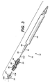
- FIGURE 3 is a perspective, exploded and partially cutaway view of a distal portion of the applier of FIG. 1.
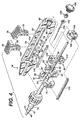
- FIGURE 4 is a perspective, exploded view of a proximal portion of the applier of FIG. 1 with a left housing half omitted.
- FIGURE 5 is perspective view of the applier of FIG. 1 with the left housing half omitted and an outer tube of the cannula partially cutaway to expose an intermediate tube and inner rod that actuate a molded actuating member that actuates the omitted anastomotic ring device, also to expose a deployment illuminator that allows confirming actuation of an anastomotic ring device by viewing through the translucent tissue walls.
- FIGURE 6 is a perspective view of the applier of FIG. 5 with the triggers and molded actuating member in an actuated position.
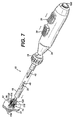
- FIGURE 7 is a perspective view of the applier of FIG. 1 in a partially actuated state.
- FIGURE 8 is a detail perspective view of a distal portion of the applier of FIG. 7 with tissue walls partially cutaway.
- FIGURE 9 is a perspective view of the applier of FIG. 1 in a fully actuated state.
- FIGURE 10 is a detail perspective view of the distal portion of the applier of FIG. 9 with tissue walls partially cutaway.
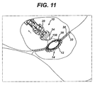
- FIGURE 11 is a detail perspective view of the distal portion of the applier returned to unactuated state and withdrawn proximally to deploy the actuated anastomotic ring device.
- FIGURE 12 is a detail perspective view of the distal portion of the applier of FIG. 1 in an unactuated position holding an anastomotic ring device advantageously fabricated with a ball end discontinuous weave.
- FIGURE 13 is a detail perspective view of the distal portion of the applier of FIG. 12 in a partially actuated position.
- FIGURE 14 is a detail perspective view of the distal portion of the applier of FIG. 12 in a fully actuated position.
- FIGURE 15 is an end view of the anastomotic ring device of FIG. 12 after actuation, depicted as a single strand discontinuous weave with a pair of ball ends.
- FIGURE 16 is an end view of the anastomotic ring device of FIG. 12 after actuation, depicted as a dual strand discontinuous weave, each strand with a pair of ball ends.
- FIGURE 17 is a detail view of a ball end of the anastomotic ring device of FIG. 12 in atraumatic contact with a tissue wall.
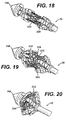
- FIGURE 18 is a detail perspective view of the distal portion of the applier of FIG. 1 in an unactuated position holding an anastomotic ring device advantageously fabricated with a loop end discontinuous weave.
- FIGURE 19 is a detail perspective view of the distal portion of the applier of FIG. 18 in a partially actuated position.
- FIGURE 20 is a detail perspective view of the distal portion of the applier of FIG. 18 in a fully actuated position.
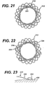
- FIGURE 21 is an end view of an anastomotic ring device after actuation, depicted as a dual strand discontinuous weave each strand with straight ends.
- FIGURE 22 is an end view of the anastomotic ring device of FIG. 18 after actuation, depicted as a dual strand discontinuous weave, each strand with a pair of loop ends.
- FIGURE 23 is a detail view of a loop end of the anastomotic ring device of FIG. 18 in atraumatic contact with a tissue wall.
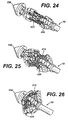
- FIGURE 24 is a detail perspective view of the distal portion of the applier of FIG. 1 in an unactuated position holding an anastomotic ring device advantageously fabricated with a hook end discontinuous weave.
- FIGURE 25 is a detail perspective view of the distal portion of the applier of FIG. 24 in a partially actuated position.
- FIGURE 26 is a detail perspective view of the distal portion of the applier of FIG. 24 in a fully actuated position.
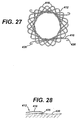
- FIGURE 27 is an end view of an anastomotic ring device after actuation, depicted as a dual strand discontinuous weave each strand with a pair of hook ends.
- FIGURE 28 is a detail view of a loop end of the anastomotic ring device of FIG. 24 in traumatic contact with a tissue wall.
- FIGURE 29 is a side view of an anastomotic ring device including a helical actuation coil and constrained within a sheath.
- FIGURE 30 is a perspective view of the anastomotic ring device of FIG. 30 in an actuated condition.
- FIGURE 31 is a side view of a generally known anastomotic ring having converging distal petals.
- FIGURE 32 is a detail view of the generally-known anastomotic ring of FIG. 31.
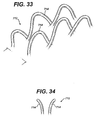
- FIGURE 33 is a perspective view of an anastomotic ring device incorporating diverging petals.
- FIGURE 34 is a side detail view of the diverging petals of the anastomotic ring device of FIG. 33.
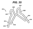
- FIGURE 35 is side view of two arcuate members with a reduced radius point for an anastomotic ring device.
- FIG. 1 depicts an applier 10 that advantageously laparoscopically or endoscopically deploys and actuates an anastomotic ring device 12 from a generally cylindrical shape to one having properties of a hollow rivet, or ring, capable of forming an astomotic attachment at an anastomosis target site, such as in a bariatric gastric bypass of a morbidly obese patient 16.
- the anastomotic ring device 12 comprises a shape memory effect (SME) material such as nitinol that further assists in actuation to an engaging hollow rivet shape.
- SME shape memory effect
- proximal and distal are used herein with reference to a clinician gripping a handle of the applier 10.
- spatial terms such as “right”, “left”, “vertical” and “horizontal” are used herein with respect to the drawings.
- surgical instruments are used in many orientations and positions, and these terms are not intended to be limiting and absolute.
- aspects of the invention have application to surgical procedures performed endoscopically and laparoscopically, as well as an open procedure. Use herein of one of these or similar terms should not be construed to limit the present invention for use in only one category of surgical procedure.
- the applier 10 has the anastomotic ring device 12 advantageously retained in a generally cylindrical shape distal to an outer tube 18 upon a molded actuation member 20 forming a cannula 22 that distally terminates in a tapered tip 24.
- This tapered tip 24 presents a distal piercing surface 26 to form an anastomotic opening 28 through apposite tissue walls 30, 32 of two gastrointestinal passages.
- the tapered tip 24 may advantageously include illumination features that allow confirmation of placement and actuation of the anastomotic ring device 12 when viewed from a proximal direction through translucent tissue walls 30, 32.
- a handle 34 proximal to the cannula 22, includes a pair of longitudinally aligned triggers 36, 38.
- the proximal trigger 36 shown at its most proximal, unfired position, is coupled to proximal leaves 40 of the molded actuation member 20 via an intermediate tube 42 of the cannula 22. Distal movement of the proximal trigger 36 thus causes longitudinal distal movement of the intermediate tube 42 and proximal leaves 40, which outwardly actuate like an umbrella by a hinged relationship to a central portion 44 of the molded actuation member 20.
- distal trigger 28 shown at its most distal, unfired position, is coupled to distal leaves 46 of the molded actuation member 20 via an internal rod 48 that is coupled for movement within the intermediate tube 42.
- Proximal movement of the distal trigger 38 causes longitudinal proximal movement of the rod 48 and distal leaves 50 of the molded actuation member 20, which outwardly actuate by a hinged relationship to the central portion 44.
- a cavity 52 includes proximal and distal apertures 54, 56 to allow the longitudinal movement of the proximal and distal triggers 36, 38 respectively.
- Each trigger 36, 38 includes a right opening aperture 58 that engage for longitudinal movement a leftward projecting track 60 formed within the cavity 52 of a right half shell of the handle 34.
- a first, second and third lateral ridge 62, 64, 66 across the bottom of the cavity 52 define a first, second, third, and fourth cavity segment 68, 70, 72, 74 respectively.
- a first block 76, formed from left and right halves 78, 80 is positioned for movement within the first cavity segment 68.
- a longitudinal central hole 82 defined between the two halves 78, 80 engages and moves with a terminating proximal end 84 of the intermediate tube 42.
- the internal rod 48 passes on through the first block 76 into the second, third and fourth cavity segments 70-74 into sliding contact with a hole 86 passing through a proximal end 88 of the handle 34.
- a second spacer block 90 locked within the second cavity segment 70 has a longitudinal central hole 92 defined between its left and right halves 94, 95 that slidingly contacts and support the internal rod 48.
- a third sliding block 96 has a longitudinal central hole 98 defined between its upper and lower halves 100, 102 that engage and move with the internal rod 48.
- a lower portion 104 of the distal trigger 38 is attached to a distal face of the third sliding block 96.
- a fourth sliding block 106 within the fourth cavity segment 74 has a longitudinal central hole 108 that slidingly contacts the internal rod 48.
- a lower portion 114 of the proximal trigger 36 is attached to a proximal face of the fourth sliding block 106.
- a link 116 is attached to the left sides of the first and fourth sliding blocks 76, 106.
- the triggers 36, 38 have been slid toward one another to actuate the molded actuating member 20.
- the distal trigger 38 has been moved proximally, moving the third sliding block 96 and internal rod 48, the distal terminating end of the latter being attached to tapered tip 24.
- the tapered tip thus moves toward the distal end of the intermediate tube 42.
- the proximal trigger 36 has been moved distally, moving fourth sliding block 106, link 116, first sliding block 76, and intermediate tube 42 also distally.
- the molded actuating member 20 is compressed between the inwardly moving tapered tip 24 and intermediate tube 42.
- the distal leaves 50 actuate lateral to the longitudinal axis, and move toward and interdigitate with the proximal leaves 40. This movement expedites actuating of an anastomotic ring device (not shown in FIG. 6).
- the tapered tip 24 of the applier 10 is inserted through a trocar port into a tissue passage that has been placed proximate to another tissue passage that are to be anastomotically joined (See FIGS. 1-2).
- the tapered tip 24 and a distal half of the molded actuating member 20 and anastomotic ring device 12 are inserted through an anastomotic opening 28 formed therebetween and then the applier is actuated, with a partially actuated applier 10 being depicted in FIGS. 7-8.
- the proximal and distal leaves 40, 50 are shown as having gripping slots 118 that grip respective petals 120 of the anastomotic ring device 12, especially in its unactuated, generally cylindrical shape.
- An inwardly directed retention tip 121 or other gripping features in the gripping slots 118 may be incorporated to enhance retention. These gripping slots 118 assist in preventing the anastomotic ring device 12 from slipping off of the applier 10 or being inappropriately placed thereon for actuation.
- the applier 10 has been fully actuated, forming the anastomotic ring device 12 into a hollow rivet shape to form the anastomotic attachment between tissue walls 30, 32.
- the fully actuated proximal and distal leaves 40, 50 cause the petals 120 to disengage from the gripping slots 118.
- the applier 10 is returned to an unactuated condition and the actuated anastomotic ring device 12 deployed by withdrawing the tapered tip 24 from the anastomotic opening 28 and ring device 12, as depicted in FIG. 11.
- FIGS. 7, 9 a distal portion of the anastomotic ring device 12 are depicted in phantom to illustrate their actuated position. This phantom depiction is also suggestive of a clinical advantage of being able to view the deployment condition from a proximal point of view. Typically, an endoscope will view the anastomotic - opening 28 from a proximal position.
- adding a deployment illumination feature to the applier 10 provides this ability to view deployment through translucent tissue walls.
- an illumination power source (e.g., battery) 150 and control (e.g., switch) 152 are incorporated into the handle 34 with a conductor, depicted as a twisted wire pair 154 passing through the internal rod 48 to the tapered tip 24, which includes a proximally directed electroluminescence device 156.
- a conductor depicted as a twisted wire pair 154 passing through the internal rod 48 to the tapered tip 24, which includes a proximally directed electroluminescence device 156.
- conductive ink traces may be applied longitudinally down portions of the applier 10 to provide an electrical circuit to the tapered tip 24.
- An externally accessible push button 158 drives the power source 150 against the control 152, creating an illumination circuit with the electroluminescence device 156.
- the molded actuating member 20 may be formed of a fluorescent or electroluminescent material that is either stimulated prior to insertion or receives light from a light source of the applier 10.
- an advantageous approach to fabricating an anastomotic ring device 212 includes adding ball ends 214 to each wire strand 216.
- a hole is laser formed in each ball end 214 and then the ball end 214 is crimped onto the wire strand 216.
- the ball ends 214 assist in preventing unraveling of petals 218 formed by the woven strands 216.
- the ball ends 214 form an atraumatic contact with a tissue wall 220, as depicted in FIG. 17.
- an anastomotic ring device 312 in FIGS. 18-23 is formed by one or more wire strands 316 whose ends are not attached to one another but instead positioned within the confines of petals 318 of the anastomotic ring device 312. Specifically, in FIG. 21, each strand 316 terminates in a generally straight end 322. In FIGS. 18-20, 22-23, each strand terminates in a loop end 324. In each instance, positioning each end 322, 324 within petals 318 of the anastomotic ring device 312 avoids interference with an applier while also simplifying manufacturer.
- an anastomotic ring device 412 in FIGS. 24-28 is formed by one or more wire strands 416 whose ends are not attached to one another but instead are positioned outside of petals 418 of the woven strands 416.
- each strand 416 traumatically engages a tissue wall 420 with hook ends426 interdigitated between the petals 416.
- an anastomotic ring device 512 includes a helical wire assist spring 530 fabricated from an SME material (e.g., nitinol) or from spring steel.
- SME material e.g., nitinol
- the woven material of a stent portion 532 of the anastomotic ring device 512 need not be of an SME material, or at least need not rely entirely upon its SME properties to effect actuation.
- the helical wire assist spring 530 enables selection of a stent portion 532 of a desired wire thickness and of a desired material.
- the stent portion 532 may even be of plastic or longitudinally cut discrete sections of a continuously woven wire braid that provide no inherent actuating capability.
- the wire assisted anastomotic ring device 512 is depicted in a generally cylindrical shape constrained by a lumen 534, which may be an applier. It will be appreciated that the wire assisted anastomotic ring device 512 may advantageously be implanted by use of the applier 10 described above, which would advantageously affirmatively grip the wire assisted anastomotic ring device to hold it in the stressed, unactuated position prior to implantation.
- the generally-known nitinol ring device 600 includes converging looped petals 602 whose distal end flare lateral to the longitudinal axis when viewed in their stressed, generally cylindrical state, and interdigitate when viewed in their relaxed, actuated state, as depicted in FIGS. 31-32. It is believed that such deflected petals 602 engage the tissue walls in a beneficial fashion. However, the resulting increase in outward slope of each petal 602 imposes an increasing amount of friction to self-actuation of the generally-known nitinol ring device 600, negating any advantage of engagement, requiring more force to self-deploy generally-known nitinol ring device 600.
- nitinol ring device 600 deploys, portions of wire forming generally-known nitinol ring device 600 move relative to each other while in contact.
- the curvature of the wire winding of generally-known nitinol ring device 600 forms local maxima and minima for a contacting wire to traverse.
- the converging looped petals cause a local minimum for a contacting wire portion that the contacting wire portion must overcome.
- An increasing force gradient opposing deployment occurs, and must be overcome by the internal stored energy of the generally-known nitinol ring device 600 to complete deployment.
- an anastomotic ring device 712 advantageously includes distal looped petals 714 that are divergent (flared away) from each other when the ring device 712 is in its relaxed, hollow rivet (ring) shape as depicted. It is further believed that deflecting the distal portions of each petal 714 away from the tissue walls may decrease excessive pressure at the anastomotic attachment site without significant degradation to its required amount of attachment forces. Moreover, for anastomotic ring devices 712 that are not formed of an absorbable material, this configuration may advantageously later more readily detach after the anastomotic attachment is permanently formed between tissue walls.
- Anastomotic ring device 712 with divergent (flared away) petals, will a cause a maximum in force tending to urge the anastomotic ring device 712 towards the actuated ring state.
- an anastomotic ring device 812 includes petals 814 whose distal portion 816 is formed with a small radius relative to its more proximal portions 818 that overlap each other and slide across each other during actuation.
- straight portions 820 between the distal and proximal portions 816, 818 may be shaped such that in the stressed, cylindrical shape of the ring device 812 that the petals 814 are urged toward the actuated ring state.
- the divergent position of the petals may further be enhanced by SME treatment of these distal portions wherein the stressed, generally cylindrical state of the ring device 814 may include a straight petal or even a converging petal for purposes such as enhancing user of an applier 10 and/or achieving a good anastomotic attachment immediately upon actuation with an eventual steady-state actuation position being as depicted.
- an applier 10 has been advantageously depicted that assists in actuating the anastomotic ring device 10, it should be appreciated that the anastomotic ring device 10 includes enhanced reliability and performance in self-actuating and thus may be inserted by other means, to include insertion through the opening and released without the application of an external actuating force.
Landscapes
- Health & Medical Sciences (AREA)
- Surgery (AREA)
- Life Sciences & Earth Sciences (AREA)
- Medical Informatics (AREA)
- Nuclear Medicine, Radiotherapy & Molecular Imaging (AREA)
- Engineering & Computer Science (AREA)
- Biomedical Technology (AREA)
- Heart & Thoracic Surgery (AREA)
- Physiology (AREA)
- Molecular Biology (AREA)
- Animal Behavior & Ethology (AREA)
- General Health & Medical Sciences (AREA)
- Public Health (AREA)
- Veterinary Medicine (AREA)
- Surgical Instruments (AREA)
- Acyclic And Carbocyclic Compounds In Medicinal Compositions (AREA)
Abstract
Description
Claims (10)
- An anastomotic device, comprising a woven tube of at least one wire strand, the woven tube having each longitudinal end terminate in circumferential petals, the woven tube having an unactuated position of a generally cylindrical shape and an actuated position of a hollow rivet shape respectively for insertion through and for forming an anastomotic attachment between two proximate tissue walls at an anastomotic surgical site, wherein each of the at least one wire strand includes unattached ends.
- The anastomotic device of claim 1, wherein at least one unattached end of at least one wire strand terminates in a ball.
- The anastomotic device of claim 1, wherein at least one unattached end of at least one wire strand terminates in loop.
- The anastomotic device of claim 1, wherein at least one unattached end of at least one wire strand terminates in a hook registered to engage a tissue wall of the anastomotic surgical site when the woven tube is in an actuated position.
- An anastomotic device, comprising:a woven tube of at least one wire strand, the woven tube having each longitudinal end terminate in circumferential petals, the woven tube having an unactuated position of a generally cylindrical shape and an actuated position of a hollow rivet shape respectively for insertion through and for forming an anastomotic attachment between two proximate tissue walls at an anastomotic surgical site, anda helical spring coupled to the woven tube for imparting an actuating force thereto to urge the woven tube from the unactuated to the actuated position.
- The anastomotic device of claim 5, wherein the helical spring comprises a spring steel strand formed into a helical shape.
- The anastomotic device of claim 5, wherein the helical spring compresses a Shape Memory Effect material.
- The anastomotic device of claim 5, wherein the woven tube comprises a longitudinally cut segment of a continuous woven cylindrical tube.
- The anastomotic device of claim 5 wherein the woven tube comprises a Shape Memory Effect material.
- An anastomotic device, comprising a woven tube of at least one wire strand, the woven tube having each longitudinal end terminate in circumferential petals, the woven tube having an unactuated position of a generally cylindrical shape and an actuated position of a hollow rivet shape respectively for insertion through and for forming an anastomotic attachment between two proximate tissue walls at an anastomotic surgical site, an underlying portion of each petal presenting a monotonic slope to an overlying portion of an adjacent petal for mitigating resistance to actuation.
Applications Claiming Priority (2)
| Application Number | Priority Date | Filing Date | Title |
|---|---|---|---|
| US674371 | 2003-09-30 | ||
| US10/674,371 US7608086B2 (en) | 2003-09-30 | 2003-09-30 | Anastomosis wire ring device |
Publications (3)
| Publication Number | Publication Date |
|---|---|
| EP1520528A2 true EP1520528A2 (en) | 2005-04-06 |
| EP1520528A3 EP1520528A3 (en) | 2006-08-09 |
| EP1520528B1 EP1520528B1 (en) | 2009-09-16 |
Family
ID=34313958
Family Applications (1)
| Application Number | Title | Priority Date | Filing Date |
|---|---|---|---|
| EP04256019A Expired - Lifetime EP1520528B1 (en) | 2003-09-30 | 2004-09-30 | Anastomosis wire ring device |
Country Status (10)
| Country | Link |
|---|---|
| US (1) | US7608086B2 (en) |
| EP (1) | EP1520528B1 (en) |
| JP (1) | JP4658555B2 (en) |
| CN (1) | CN1636528A (en) |
| AT (1) | ATE442813T1 (en) |
| AU (1) | AU2004216633A1 (en) |
| BR (1) | BRPI0405024B1 (en) |
| CA (1) | CA2483248C (en) |
| DE (1) | DE602004023163D1 (en) |
| MX (1) | MXPA04009609A (en) |
Cited By (5)
| Publication number | Priority date | Publication date | Assignee | Title |
|---|---|---|---|---|
| EP1719459A1 (en) * | 2005-05-05 | 2006-11-08 | Ethicon Endo-Surgery, Inc. | Anastomosis applier |
| US8211186B2 (en) | 2009-04-03 | 2012-07-03 | Metamodix, Inc. | Modular gastrointestinal prostheses |
| US8282598B2 (en) | 2009-07-10 | 2012-10-09 | Metamodix, Inc. | External anchoring configurations for modular gastrointestinal prostheses |
| US8702641B2 (en) | 2009-04-03 | 2014-04-22 | Metamodix, Inc. | Gastrointestinal prostheses having partial bypass configurations |
| US11266411B2 (en) | 2014-08-14 | 2022-03-08 | W. L. Gore & Associates, Inc. | Anastomosis devices |
Families Citing this family (118)
| Publication number | Priority date | Publication date | Assignee | Title |
|---|---|---|---|---|
| US7338433B2 (en) | 2002-08-13 | 2008-03-04 | Allergan, Inc. | Remotely adjustable gastric banding method |
| BR0306183A (en) * | 2002-08-28 | 2004-10-19 | Inamed Medical Products Corp | Fatigue Resistant Gastric Banding Device |
| US7452363B2 (en) * | 2003-09-30 | 2008-11-18 | Ethicon Endo-Surgery, Inc. | Applier for fastener for single lumen access anastomosis |
| US20050070939A1 (en) * | 2003-09-30 | 2005-03-31 | Jean Beaupre | Unfolding anastomosis ring device |
| US7309341B2 (en) * | 2003-09-30 | 2007-12-18 | Ethicon Endo-Surgery, Inc. | Single lumen anastomosis applier for self-deploying fastener |
| US8211142B2 (en) * | 2003-09-30 | 2012-07-03 | Ortiz Mark S | Method for hybrid gastro-jejunostomy |
| AU2005208721B2 (en) | 2004-01-23 | 2010-09-23 | Boston Scientific Scimed, Inc. | Releasably-securable one-piece adjustable gastric band |
| DK1725193T3 (en) * | 2004-03-08 | 2009-11-30 | Allergan Medical S A | Closing system for tubular members |
| ATE517652T1 (en) * | 2004-03-18 | 2011-08-15 | Allergan Inc | DEVICE FOR ADJUSTING THE VOLUME OF INTRAGASTRAL BALLOONS |
| US8251888B2 (en) | 2005-04-13 | 2012-08-28 | Mitchell Steven Roslin | Artificial gastric valve |
| US7462186B2 (en) * | 2005-05-03 | 2008-12-09 | Ethicon Endo-Surgery, Inc. | Anastomotic ring applier device utilizing an electroactive polymer |
| US7470275B2 (en) * | 2005-05-03 | 2008-12-30 | Ethicon Endo-Surgery, Inc. | Anastomotic ring applier device providing forward and retrograde visualization |
| US7547311B2 (en) * | 2005-05-03 | 2009-06-16 | Ethicon Endo-Surgery, Inc. | Spring-based firing mechanism for anastomotic ring applier |
| US7632285B2 (en) * | 2005-05-03 | 2009-12-15 | Ethicon Endo-Surgery, Inc. | Sheath for enabling insertion and extraction of anastomotic ring applier |
| US7645287B2 (en) * | 2005-05-03 | 2010-01-12 | Ethicon Endo-Surgery, Inc. | Articulating anastomotic ring applier |
| US7445622B2 (en) * | 2005-05-05 | 2008-11-04 | Ethicon Endo-Surgery, Inc. | Anastomotic ring applier with double motion actuation |
| US7645288B2 (en) * | 2005-05-05 | 2010-01-12 | Ethicon Endo-Surgery, Inc. | Anastomotic ring applier with inflatable members |
| US20070021759A1 (en) * | 2005-07-22 | 2007-01-25 | Ethicon Endo-Surgery, Inc. | Flexible endoscopic anastomotic ring applier device |
| US7591828B2 (en) * | 2005-07-22 | 2009-09-22 | Ethicon Endo-Surgery, Inc. | Resposable anastomotic ring applier device |
| US7798992B2 (en) * | 2005-11-04 | 2010-09-21 | Ethicon Endo-Surgery, Inc. | Lumen traversing device |
| CA2630021C (en) * | 2005-11-17 | 2013-08-13 | Microvention, Inc. | Three-dimensional complex coil |
| US7651017B2 (en) * | 2005-11-23 | 2010-01-26 | Ethicon Endo-Surgery, Inc. | Surgical stapler with a bendable end effector |
| US20070123917A1 (en) * | 2005-11-29 | 2007-05-31 | Ortiz Mark S | Anastomotic device promoting tissue necrosis |
| US7798954B2 (en) | 2006-01-04 | 2010-09-21 | Allergan, Inc. | Hydraulic gastric band with collapsible reservoir |
| US8043206B2 (en) | 2006-01-04 | 2011-10-25 | Allergan, Inc. | Self-regulating gastric band with pressure data processing |
| US7625392B2 (en) | 2006-02-03 | 2009-12-01 | James Coleman | Wound closure devices and methods |
| US8221438B2 (en) * | 2006-02-17 | 2012-07-17 | Ethicon Endo-Surgery, Inc. | Lumen reduction methods and devices |
| US20070198032A1 (en) * | 2006-02-22 | 2007-08-23 | Ethicon Endo-Surgery, Inc. | Methods and devices for fastener removal |
| US20070225556A1 (en) * | 2006-03-23 | 2007-09-27 | Ethicon Endo-Surgery, Inc. | Disposable endoscope devices |
| US7615004B2 (en) | 2006-03-30 | 2009-11-10 | Ethicon Endo-Surgery, Inc. | Endoscopic ancillary attachment devices |
| US20070239179A1 (en) * | 2006-03-31 | 2007-10-11 | Ethicon Endo-Surgery, Inc. | Compliant Gastroplasty: Devices And Methods |
| US20070276409A1 (en) * | 2006-05-25 | 2007-11-29 | Ethicon Endo-Surgery, Inc. | Endoscopic gastric restriction methods and devices |
| US7635373B2 (en) * | 2006-05-25 | 2009-12-22 | Ethicon Endo-Surgery, Inc. | Absorbable gastric restriction devices and methods |
| US7527185B2 (en) * | 2006-07-12 | 2009-05-05 | Niti Surgical Solutions Ltd. | Compression anastomosis ring assembly and applicator for use therewith |
| US8205782B2 (en) * | 2006-07-12 | 2012-06-26 | Niti Surgical Solutions Ltd. | Compression assemblies and applicators for use therewith |
| US8603138B2 (en) | 2006-10-04 | 2013-12-10 | Ethicon Endo-Surgery, Inc. | Use of an adhesive to treat intraluminal bleeding |
| US7914511B2 (en) * | 2006-10-18 | 2011-03-29 | Ethicon Endo-Surgery, Inc. | Use of biosurgical adhesive as bulking agent |
| US8876844B2 (en) | 2006-11-01 | 2014-11-04 | Ethicon Endo-Surgery, Inc. | Anastomosis reinforcement using biosurgical adhesive and device |
| CA2664557C (en) | 2006-11-07 | 2015-05-26 | Corvia Medical, Inc. | Devices and methods for the treatment of heart failure |
| US10413284B2 (en) | 2006-11-07 | 2019-09-17 | Corvia Medical, Inc. | Atrial pressure regulation with control, sensing, monitoring and therapy delivery |
| US9232997B2 (en) | 2006-11-07 | 2016-01-12 | Corvia Medical, Inc. | Devices and methods for retrievable intra-atrial implants |
| US8740962B2 (en) * | 2006-11-07 | 2014-06-03 | Dc Devices, Inc. | Prosthesis for retrieval and deployment |
| US20110257723A1 (en) | 2006-11-07 | 2011-10-20 | Dc Devices, Inc. | Devices and methods for coronary sinus pressure relief |
| WO2008106279A1 (en) | 2007-02-28 | 2008-09-04 | Wilson-Cook Medical, Inc. | Intestinal bypass using magnets |
| US8443808B2 (en) | 2007-03-19 | 2013-05-21 | Hologic, Inc. | Methods and apparatus for occlusion of body lumens |
| IL182155A0 (en) * | 2007-03-25 | 2007-07-24 | Nir Lilach | Anastomosis suturing device and methods thereof |
| US9301761B2 (en) | 2007-10-22 | 2016-04-05 | James E. Coleman | Anastomosis devices and methods |
| CZ303081B6 (en) * | 2007-12-13 | 2012-03-21 | Ella-Cs, S. R. O. | Process for producing self-expansion biologically degradable stent |
| US8292800B2 (en) * | 2008-06-11 | 2012-10-23 | Allergan, Inc. | Implantable pump system |
| US20100016885A1 (en) * | 2008-07-21 | 2010-01-21 | Eidenschink Tracee E J | Device to close openings in body tissue |
| AU2009295960A1 (en) | 2008-09-29 | 2010-04-01 | Cardiaq Valve Technologies, Inc. | Heart valve |
| US8317677B2 (en) * | 2008-10-06 | 2012-11-27 | Allergan, Inc. | Mechanical gastric band with cushions |
| US20100185049A1 (en) * | 2008-10-22 | 2010-07-22 | Allergan, Inc. | Dome and screw valves for remotely adjustable gastric banding systems |
| US8197498B2 (en) * | 2008-11-06 | 2012-06-12 | Trinitas Ventures Ltd. | Gastric bypass devices and procedures |
| US9278019B2 (en) | 2009-04-03 | 2016-03-08 | Metamodix, Inc | Anchors and methods for intestinal bypass sleeves |
| US9173760B2 (en) | 2009-04-03 | 2015-11-03 | Metamodix, Inc. | Delivery devices and methods for gastrointestinal implants |
| WO2010127248A2 (en) * | 2009-05-01 | 2010-11-04 | Allergan, Inc. | Laparoscopic gastric band with active agents |
| US20110184229A1 (en) * | 2009-05-01 | 2011-07-28 | Allergan, Inc. | Laparoscopic gastric band with active agents |
| AU2009202301B8 (en) * | 2009-06-10 | 2009-12-03 | Cook Incorporated | Reinforcing ring |
| EP2445418B1 (en) * | 2009-06-26 | 2015-03-18 | Cook Medical Technologies LLC | Linear clamps for anastomosis |
| US20110137112A1 (en) * | 2009-08-28 | 2011-06-09 | Allergan, Inc. | Gastric band with electric stimulation |
| WO2011031400A2 (en) * | 2009-08-28 | 2011-03-17 | Allergan, Inc. | Gastric band with electric stimulation |
| US9757107B2 (en) | 2009-09-04 | 2017-09-12 | Corvia Medical, Inc. | Methods and devices for intra-atrial shunts having adjustable sizes |
| EP2496148B1 (en) | 2009-11-03 | 2013-11-20 | Cook Medical Technologies LLC | Planar clamps for anastomosis |
| US9277995B2 (en) * | 2010-01-29 | 2016-03-08 | Corvia Medical, Inc. | Devices and methods for reducing venous pressure |
| US20110201874A1 (en) * | 2010-02-12 | 2011-08-18 | Allergan, Inc. | Remotely adjustable gastric banding system |
| US8678993B2 (en) * | 2010-02-12 | 2014-03-25 | Apollo Endosurgery, Inc. | Remotely adjustable gastric banding system |
| US8758221B2 (en) * | 2010-02-24 | 2014-06-24 | Apollo Endosurgery, Inc. | Source reservoir with potential energy for remotely adjustable gastric banding system |
| US8840541B2 (en) | 2010-02-25 | 2014-09-23 | Apollo Endosurgery, Inc. | Pressure sensing gastric banding system |
| US8764624B2 (en) | 2010-02-25 | 2014-07-01 | Apollo Endosurgery, Inc. | Inductively powered remotely adjustable gastric banding system |
| US8603121B2 (en) | 2010-04-14 | 2013-12-10 | Cook Medical Technologies Llc | Systems and methods for creating anastomoses |
| US8939888B2 (en) | 2010-04-28 | 2015-01-27 | Apollo Endosurgery, Inc. | Method and system for determining the pressure of a fluid in a syringe, an access port, a catheter, and a gastric band |
| US20110270024A1 (en) | 2010-04-29 | 2011-11-03 | Allergan, Inc. | Self-adjusting gastric band having various compliant components |
| US9044298B2 (en) | 2010-04-29 | 2015-06-02 | Apollo Endosurgery, Inc. | Self-adjusting gastric band |
| US9028394B2 (en) | 2010-04-29 | 2015-05-12 | Apollo Endosurgery, Inc. | Self-adjusting mechanical gastric band |
| US20110270025A1 (en) | 2010-04-30 | 2011-11-03 | Allergan, Inc. | Remotely powered remotely adjustable gastric band system |
| US9226840B2 (en) | 2010-06-03 | 2016-01-05 | Apollo Endosurgery, Inc. | Magnetically coupled implantable pump system and method |
| US8517915B2 (en) | 2010-06-10 | 2013-08-27 | Allergan, Inc. | Remotely adjustable gastric banding system |
| WO2012007042A1 (en) | 2010-07-16 | 2012-01-19 | Ethicon Endo-Surgery, Inc. | An anastomosis device for a cholecysto-enterostomy |
| WO2012007052A1 (en) | 2010-07-16 | 2012-01-19 | Ethicon Endo-Surgery, Inc. | A device for an endoluminal cholecysto - enterostomy |
| US8698373B2 (en) | 2010-08-18 | 2014-04-15 | Apollo Endosurgery, Inc. | Pare piezo power with energy recovery |
| US9211207B2 (en) | 2010-08-18 | 2015-12-15 | Apollo Endosurgery, Inc. | Power regulated implant |
| US20120059216A1 (en) | 2010-09-07 | 2012-03-08 | Allergan, Inc. | Remotely adjustable gastric banding system |
| US8961393B2 (en) | 2010-11-15 | 2015-02-24 | Apollo Endosurgery, Inc. | Gastric band devices and drive systems |
| US12303119B2 (en) | 2011-02-10 | 2025-05-20 | Corvia Medical, Inc. | Apparatus and methods to create and maintain an intra-atrial pressure relief opening |
| WO2012109557A2 (en) | 2011-02-10 | 2012-08-16 | Dc Devices, Inc. | Apparatus and methods to create and maintain an intra-atrial pressure relief opening |
| EP3031428B1 (en) | 2011-03-08 | 2020-11-18 | W.L. Gore & Associates, Inc | Medical device for use with a stoma |
| EP4119095A1 (en) | 2011-03-21 | 2023-01-18 | Cephea Valve Technologies, Inc. | Disk-based valve apparatus |
| US8725435B2 (en) | 2011-04-13 | 2014-05-13 | Apollo Endosurgery, Inc. | Syringe-based leak detection system |
| US8685096B2 (en) * | 2011-08-23 | 2014-04-01 | Amendia, Inc. | Lumbar fusion device |
| US8876694B2 (en) | 2011-12-07 | 2014-11-04 | Apollo Endosurgery, Inc. | Tube connector with a guiding tip |
| US8961394B2 (en) | 2011-12-20 | 2015-02-24 | Apollo Endosurgery, Inc. | Self-sealing fluid joint for use with a gastric band |
| US9247930B2 (en) | 2011-12-21 | 2016-02-02 | James E. Coleman | Devices and methods for occluding or promoting fluid flow |
| US8951223B2 (en) | 2011-12-22 | 2015-02-10 | Dc Devices, Inc. | Methods and devices for intra-atrial shunts having adjustable sizes |
| US9005155B2 (en) | 2012-02-03 | 2015-04-14 | Dc Devices, Inc. | Devices and methods for treating heart failure |
| US10588611B2 (en) | 2012-04-19 | 2020-03-17 | Corvia Medical Inc. | Implant retention attachment and method of use |
| US9649480B2 (en) | 2012-07-06 | 2017-05-16 | Corvia Medical, Inc. | Devices and methods of treating or ameliorating diastolic heart failure through pulmonary valve intervention |
| AU2014207608A1 (en) | 2013-01-15 | 2015-07-30 | Metamodix, Inc. | System and method for affecting intestinal microbial flora |
| US10327778B2 (en) | 2013-02-28 | 2019-06-25 | Boston Scientific Scimed, Inc. | Stent with balloon for repair of anastomosis surgery leaks |
| US9775636B2 (en) | 2013-03-12 | 2017-10-03 | Corvia Medical, Inc. | Devices, systems, and methods for treating heart failure |
| US9561103B2 (en) | 2013-07-17 | 2017-02-07 | Cephea Valve Technologies, Inc. | System and method for cardiac valve repair and replacement |
| US10675450B2 (en) | 2014-03-12 | 2020-06-09 | Corvia Medical, Inc. | Devices and methods for treating heart failure |
| US10004509B2 (en) | 2014-05-02 | 2018-06-26 | W. L. Gore & Associates, Inc. | Anastomosis devices |
| US11712230B2 (en) | 2014-05-02 | 2023-08-01 | W. L. Gore & Associates, Inc. | Occluder and anastomosis devices |
| US11439396B2 (en) | 2014-05-02 | 2022-09-13 | W. L. Gore & Associates, Inc. | Occluder and anastomosis devices |
| US10632292B2 (en) | 2014-07-23 | 2020-04-28 | Corvia Medical, Inc. | Devices and methods for treating heart failure |
| EP3193780A1 (en) | 2014-09-18 | 2017-07-26 | Boston Scientific Scimed Inc. | Device allowing pyloric sphincter to normally function for bariatric stents |
| CN104306039B (en) * | 2014-10-24 | 2016-08-24 | 飞依诺科技(苏州)有限公司 | Stapler |
| AU2015361260B2 (en) | 2014-12-09 | 2020-04-23 | Cephea Valve Technologies, Inc. | Replacement cardiac valves and methods of use and manufacture |
| WO2016183523A1 (en) | 2015-05-14 | 2016-11-17 | Cephea Valve Technologies, Inc. | Cardiac valve delivery devices and systems |
| AU2016262564B2 (en) | 2015-05-14 | 2020-11-05 | Cephea Valve Technologies, Inc. | Replacement mitral valves |
| WO2018136959A1 (en) | 2017-01-23 | 2018-07-26 | Cephea Valve Technologies, Inc. | Replacement mitral valves |
| US10307168B2 (en) | 2015-08-07 | 2019-06-04 | Terumo Corporation | Complex coil and manufacturing techniques |
| US9622897B1 (en) | 2016-03-03 | 2017-04-18 | Metamodix, Inc. | Pyloric anchors and methods for intestinal bypass sleeves |
| KR102473258B1 (en) | 2016-05-19 | 2022-12-01 | 메타모딕스, 인코포레이티드 | Pyloric Anchor Recovery Tools and Methods |
| US11331187B2 (en) | 2016-06-17 | 2022-05-17 | Cephea Valve Technologies, Inc. | Cardiac valve delivery devices and systems |
| EP4209196A1 (en) | 2017-01-23 | 2023-07-12 | Cephea Valve Technologies, Inc. | Replacement mitral valves |
| US11724075B2 (en) | 2017-04-18 | 2023-08-15 | W. L. Gore & Associates, Inc. | Deployment constraining sheath that enables staged deployment by device section |
Family Cites Families (18)
| Publication number | Priority date | Publication date | Assignee | Title |
|---|---|---|---|---|
| US5720776A (en) | 1991-10-25 | 1998-02-24 | Cook Incorporated | Barb and expandable transluminal graft prosthesis for repair of aneurysm |
| AU689094B2 (en) * | 1993-04-22 | 1998-03-26 | C.R. Bard Inc. | Non-migrating vascular prosthesis and minimally invasive placement system therefor |
| US5725552A (en) | 1994-07-08 | 1998-03-10 | Aga Medical Corporation | Percutaneous catheter directed intravascular occlusion devices |
| DE19604817C2 (en) * | 1996-02-09 | 2003-06-12 | Pfm Prod Fuer Die Med Ag | Device for closing defect openings in the human or animal body |
| US6007544A (en) | 1996-06-14 | 1999-12-28 | Beth Israel Deaconess Medical Center | Catheter apparatus having an improved shape-memory alloy cuff and inflatable on-demand balloon for creating a bypass graft in-vivo |
| EP1051128B1 (en) * | 1998-01-30 | 2006-03-15 | St. Jude Medical ATG, Inc. | Medical graft connector or plug structures, and methods of making |
| US6152937A (en) * | 1998-11-06 | 2000-11-28 | St. Jude Medical Cardiovascular Group, Inc. | Medical graft connector and methods of making and installing same |
| US6537299B1 (en) | 1999-04-05 | 2003-03-25 | Ethicon, Inc. | Intravascular hemostasis device and method |
| CN1256066C (en) * | 2000-11-07 | 2006-05-17 | 卡拉格股份公司 | An implant used to block passages in the circulatory system |
| US6872433B2 (en) | 2001-03-27 | 2005-03-29 | The Regents Of The University Of California | Shape memory alloy/shape memory polymer tools |
| JP2004528120A (en) * | 2001-05-14 | 2004-09-16 | セント ジュード メディカル エーティージー, インコーポレイテッド | Medical implantation method and device |
| WO2003000142A2 (en) | 2001-06-20 | 2003-01-03 | Park Medical, Llc. | Anastomotic device |
| US7115136B2 (en) * | 2001-06-20 | 2006-10-03 | Park Medical Llc | Anastomotic device |
| US6543456B1 (en) | 2002-05-31 | 2003-04-08 | Ethicon Endo-Surgery, Inc. | Method for minimally invasive surgery in the digestive system |
| US7309341B2 (en) | 2003-09-30 | 2007-12-18 | Ethicon Endo-Surgery, Inc. | Single lumen anastomosis applier for self-deploying fastener |
| US20050070939A1 (en) | 2003-09-30 | 2005-03-31 | Jean Beaupre | Unfolding anastomosis ring device |
| US20050070935A1 (en) | 2003-09-30 | 2005-03-31 | Ortiz Mark S. | Single lumen access deployable ring for intralumenal anastomosis |
| US7452363B2 (en) | 2003-09-30 | 2008-11-18 | Ethicon Endo-Surgery, Inc. | Applier for fastener for single lumen access anastomosis |
-
2003
- 2003-09-30 US US10/674,371 patent/US7608086B2/en not_active Expired - Fee Related
-
2004
- 2004-09-29 CN CNA2004101023702A patent/CN1636528A/en active Pending
- 2004-09-30 JP JP2004288226A patent/JP4658555B2/en not_active Expired - Fee Related
- 2004-09-30 MX MXPA04009609A patent/MXPA04009609A/en not_active Application Discontinuation
- 2004-09-30 DE DE602004023163T patent/DE602004023163D1/en not_active Expired - Lifetime
- 2004-09-30 AT AT04256019T patent/ATE442813T1/en not_active IP Right Cessation
- 2004-09-30 AU AU2004216633A patent/AU2004216633A1/en not_active Abandoned
- 2004-09-30 EP EP04256019A patent/EP1520528B1/en not_active Expired - Lifetime
- 2004-09-30 CA CA2483248A patent/CA2483248C/en not_active Expired - Fee Related
- 2004-09-30 BR BRPI0405024-0A patent/BRPI0405024B1/en not_active IP Right Cessation
Cited By (7)
| Publication number | Priority date | Publication date | Assignee | Title |
|---|---|---|---|---|
| EP1719459A1 (en) * | 2005-05-05 | 2006-11-08 | Ethicon Endo-Surgery, Inc. | Anastomosis applier |
| US7691113B2 (en) | 2005-05-05 | 2010-04-06 | Ethicon Endo-Surgery, Inc. | Screw tip control for anastomotic ring applier |
| AU2006201803B2 (en) * | 2005-05-05 | 2012-02-23 | Ethicon Endo-Surgery, Inc. | Screw tip control for anastomotic ring applier |
| US8211186B2 (en) | 2009-04-03 | 2012-07-03 | Metamodix, Inc. | Modular gastrointestinal prostheses |
| US8702641B2 (en) | 2009-04-03 | 2014-04-22 | Metamodix, Inc. | Gastrointestinal prostheses having partial bypass configurations |
| US8282598B2 (en) | 2009-07-10 | 2012-10-09 | Metamodix, Inc. | External anchoring configurations for modular gastrointestinal prostheses |
| US11266411B2 (en) | 2014-08-14 | 2022-03-08 | W. L. Gore & Associates, Inc. | Anastomosis devices |
Also Published As
| Publication number | Publication date |
|---|---|
| CA2483248C (en) | 2012-06-19 |
| JP2005103300A (en) | 2005-04-21 |
| EP1520528A3 (en) | 2006-08-09 |
| BRPI0405024B1 (en) | 2014-06-17 |
| ATE442813T1 (en) | 2009-10-15 |
| AU2004216633A1 (en) | 2005-04-14 |
| CA2483248A1 (en) | 2005-03-30 |
| BRPI0405024A (en) | 2005-05-24 |
| EP1520528B1 (en) | 2009-09-16 |
| CN1636528A (en) | 2005-07-13 |
| US20050070934A1 (en) | 2005-03-31 |
| JP4658555B2 (en) | 2011-03-23 |
| DE602004023163D1 (en) | 2009-10-29 |
| MXPA04009609A (en) | 2005-07-12 |
| US7608086B2 (en) | 2009-10-27 |
Similar Documents
| Publication | Publication Date | Title |
|---|---|---|
| US7608086B2 (en) | Anastomosis wire ring device | |
| AU2011202357B2 (en) | Unfolding anastomosis ring device | |
| JP4658557B2 (en) | Single lumen anastomosis applier for self-positioning fasteners | |
| CA2483726C (en) | Single lumen access deployable ring for intralumenal anastomosis | |
| US7452363B2 (en) | Applier for fastener for single lumen access anastomosis | |
| AU2011202587A1 (en) | Anastomosis wire ring device |
Legal Events
| Date | Code | Title | Description |
|---|---|---|---|
| PUAI | Public reference made under article 153(3) epc to a published international application that has entered the european phase |
Free format text: ORIGINAL CODE: 0009012 |
|
| AK | Designated contracting states |
Kind code of ref document: A2 Designated state(s): AT BE BG CH CY CZ DE DK EE ES FI FR GB GR HU IE IT LI LU MC NL PL PT RO SE SI SK TR |
|
| AX | Request for extension of the european patent |
Extension state: AL HR LT LV MK |
|
| PUAL | Search report despatched |
Free format text: ORIGINAL CODE: 0009013 |
|
| AK | Designated contracting states |
Kind code of ref document: A3 Designated state(s): AT BE BG CH CY CZ DE DK EE ES FI FR GB GR HU IE IT LI LU MC NL PL PT RO SE SI SK TR |
|
| AX | Request for extension of the european patent |
Extension state: AL HR LT LV MK |
|
| 17P | Request for examination filed |
Effective date: 20070125 |
|
| AKX | Designation fees paid |
Designated state(s): AT BE BG CH CY CZ DE DK EE ES FI FR GB GR HU IE IT LI LU MC NL PL PT RO SE SI SK TR |
|
| 17Q | First examination report despatched |
Effective date: 20070905 |
|
| GRAP | Despatch of communication of intention to grant a patent |
Free format text: ORIGINAL CODE: EPIDOSNIGR1 |
|
| GRAS | Grant fee paid |
Free format text: ORIGINAL CODE: EPIDOSNIGR3 |
|
| GRAA | (expected) grant |
Free format text: ORIGINAL CODE: 0009210 |
|
| AK | Designated contracting states |
Kind code of ref document: B1 Designated state(s): AT BE BG CH CY CZ DE DK EE ES FI FR GB GR HU IE IT LI LU MC NL PL PT RO SE SI SK TR |
|
| REG | Reference to a national code |
Ref country code: GB Ref legal event code: FG4D |
|
| REG | Reference to a national code |
Ref country code: CH Ref legal event code: EP |
|
| REG | Reference to a national code |
Ref country code: IE Ref legal event code: FG4D |
|
| REF | Corresponds to: |
Ref document number: 602004023163 Country of ref document: DE Date of ref document: 20091029 Kind code of ref document: P |
|
| PG25 | Lapsed in a contracting state [announced via postgrant information from national office to epo] |
Ref country code: SE Free format text: LAPSE BECAUSE OF FAILURE TO SUBMIT A TRANSLATION OF THE DESCRIPTION OR TO PAY THE FEE WITHIN THE PRESCRIBED TIME-LIMIT Effective date: 20090916 Ref country code: FI Free format text: LAPSE BECAUSE OF FAILURE TO SUBMIT A TRANSLATION OF THE DESCRIPTION OR TO PAY THE FEE WITHIN THE PRESCRIBED TIME-LIMIT Effective date: 20090916 |
|
| PG25 | Lapsed in a contracting state [announced via postgrant information from national office to epo] |
Ref country code: SI Free format text: LAPSE BECAUSE OF FAILURE TO SUBMIT A TRANSLATION OF THE DESCRIPTION OR TO PAY THE FEE WITHIN THE PRESCRIBED TIME-LIMIT Effective date: 20090916 Ref country code: NL Free format text: LAPSE BECAUSE OF FAILURE TO SUBMIT A TRANSLATION OF THE DESCRIPTION OR TO PAY THE FEE WITHIN THE PRESCRIBED TIME-LIMIT Effective date: 20090916 Ref country code: PL Free format text: LAPSE BECAUSE OF FAILURE TO SUBMIT A TRANSLATION OF THE DESCRIPTION OR TO PAY THE FEE WITHIN THE PRESCRIBED TIME-LIMIT Effective date: 20090916 |
|
| NLV1 | Nl: lapsed or annulled due to failure to fulfill the requirements of art. 29p and 29m of the patents act | ||
| PG25 | Lapsed in a contracting state [announced via postgrant information from national office to epo] |
Ref country code: CY Free format text: LAPSE BECAUSE OF FAILURE TO SUBMIT A TRANSLATION OF THE DESCRIPTION OR TO PAY THE FEE WITHIN THE PRESCRIBED TIME-LIMIT Effective date: 20090916 |
|
| PG25 | Lapsed in a contracting state [announced via postgrant information from national office to epo] |
Ref country code: MC Free format text: LAPSE BECAUSE OF NON-PAYMENT OF DUE FEES Effective date: 20090930 Ref country code: EE Free format text: LAPSE BECAUSE OF FAILURE TO SUBMIT A TRANSLATION OF THE DESCRIPTION OR TO PAY THE FEE WITHIN THE PRESCRIBED TIME-LIMIT Effective date: 20090916 Ref country code: RO Free format text: LAPSE BECAUSE OF FAILURE TO SUBMIT A TRANSLATION OF THE DESCRIPTION OR TO PAY THE FEE WITHIN THE PRESCRIBED TIME-LIMIT Effective date: 20090916 Ref country code: CZ Free format text: LAPSE BECAUSE OF FAILURE TO SUBMIT A TRANSLATION OF THE DESCRIPTION OR TO PAY THE FEE WITHIN THE PRESCRIBED TIME-LIMIT Effective date: 20090916 Ref country code: PT Free format text: LAPSE BECAUSE OF FAILURE TO SUBMIT A TRANSLATION OF THE DESCRIPTION OR TO PAY THE FEE WITHIN THE PRESCRIBED TIME-LIMIT Effective date: 20100118 Ref country code: ES Free format text: LAPSE BECAUSE OF FAILURE TO SUBMIT A TRANSLATION OF THE DESCRIPTION OR TO PAY THE FEE WITHIN THE PRESCRIBED TIME-LIMIT Effective date: 20091227 |
|
| REG | Reference to a national code |
Ref country code: CH Ref legal event code: PL |
|
| PG25 | Lapsed in a contracting state [announced via postgrant information from national office to epo] |
Ref country code: SK Free format text: LAPSE BECAUSE OF FAILURE TO SUBMIT A TRANSLATION OF THE DESCRIPTION OR TO PAY THE FEE WITHIN THE PRESCRIBED TIME-LIMIT Effective date: 20090916 |
|
| PG25 | Lapsed in a contracting state [announced via postgrant information from national office to epo] |
Ref country code: AT Free format text: LAPSE BECAUSE OF FAILURE TO SUBMIT A TRANSLATION OF THE DESCRIPTION OR TO PAY THE FEE WITHIN THE PRESCRIBED TIME-LIMIT Effective date: 20090916 Ref country code: BE Free format text: LAPSE BECAUSE OF FAILURE TO SUBMIT A TRANSLATION OF THE DESCRIPTION OR TO PAY THE FEE WITHIN THE PRESCRIBED TIME-LIMIT Effective date: 20090916 |
|
| PLBE | No opposition filed within time limit |
Free format text: ORIGINAL CODE: 0009261 |
|
| STAA | Information on the status of an ep patent application or granted ep patent |
Free format text: STATUS: NO OPPOSITION FILED WITHIN TIME LIMIT |
|
| PG25 | Lapsed in a contracting state [announced via postgrant information from national office to epo] |
Ref country code: DK Free format text: LAPSE BECAUSE OF FAILURE TO SUBMIT A TRANSLATION OF THE DESCRIPTION OR TO PAY THE FEE WITHIN THE PRESCRIBED TIME-LIMIT Effective date: 20090916 Ref country code: IE Free format text: LAPSE BECAUSE OF NON-PAYMENT OF DUE FEES Effective date: 20090930 |
|
| 26N | No opposition filed |
Effective date: 20100617 |
|
| PG25 | Lapsed in a contracting state [announced via postgrant information from national office to epo] |
Ref country code: GR Free format text: LAPSE BECAUSE OF FAILURE TO SUBMIT A TRANSLATION OF THE DESCRIPTION OR TO PAY THE FEE WITHIN THE PRESCRIBED TIME-LIMIT Effective date: 20091217 Ref country code: LI Free format text: LAPSE BECAUSE OF NON-PAYMENT OF DUE FEES Effective date: 20090930 Ref country code: CH Free format text: LAPSE BECAUSE OF NON-PAYMENT OF DUE FEES Effective date: 20090930 |
|
| PG25 | Lapsed in a contracting state [announced via postgrant information from national office to epo] |
Ref country code: BG Free format text: LAPSE BECAUSE OF FAILURE TO SUBMIT A TRANSLATION OF THE DESCRIPTION OR TO PAY THE FEE WITHIN THE PRESCRIBED TIME-LIMIT Effective date: 20090930 |
|
| PG25 | Lapsed in a contracting state [announced via postgrant information from national office to epo] |
Ref country code: LU Free format text: LAPSE BECAUSE OF NON-PAYMENT OF DUE FEES Effective date: 20090930 |
|
| PG25 | Lapsed in a contracting state [announced via postgrant information from national office to epo] |
Ref country code: HU Free format text: LAPSE BECAUSE OF FAILURE TO SUBMIT A TRANSLATION OF THE DESCRIPTION OR TO PAY THE FEE WITHIN THE PRESCRIBED TIME-LIMIT Effective date: 20100317 |
|
| PG25 | Lapsed in a contracting state [announced via postgrant information from national office to epo] |
Ref country code: TR Free format text: LAPSE BECAUSE OF FAILURE TO SUBMIT A TRANSLATION OF THE DESCRIPTION OR TO PAY THE FEE WITHIN THE PRESCRIBED TIME-LIMIT Effective date: 20090916 |
|
| REG | Reference to a national code |
Ref country code: FR Ref legal event code: PLFP Year of fee payment: 13 |
|
| REG | Reference to a national code |
Ref country code: FR Ref legal event code: PLFP Year of fee payment: 14 |
|
| REG | Reference to a national code |
Ref country code: FR Ref legal event code: PLFP Year of fee payment: 15 |
|
| PGFP | Annual fee paid to national office [announced via postgrant information from national office to epo] |
Ref country code: IT Payment date: 20190917 Year of fee payment: 16 Ref country code: FR Payment date: 20190815 Year of fee payment: 16 Ref country code: DE Payment date: 20190917 Year of fee payment: 16 |
|
| PGFP | Annual fee paid to national office [announced via postgrant information from national office to epo] |
Ref country code: GB Payment date: 20190926 Year of fee payment: 16 |
|
| REG | Reference to a national code |
Ref country code: DE Ref legal event code: R119 Ref document number: 602004023163 Country of ref document: DE |
|
| GBPC | Gb: european patent ceased through non-payment of renewal fee |
Effective date: 20200930 |
|
| PG25 | Lapsed in a contracting state [announced via postgrant information from national office to epo] |
Ref country code: DE Free format text: LAPSE BECAUSE OF NON-PAYMENT OF DUE FEES Effective date: 20210401 Ref country code: FR Free format text: LAPSE BECAUSE OF NON-PAYMENT OF DUE FEES Effective date: 20200930 |
|
| PG25 | Lapsed in a contracting state [announced via postgrant information from national office to epo] |
Ref country code: GB Free format text: LAPSE BECAUSE OF NON-PAYMENT OF DUE FEES Effective date: 20200930 |
|
| PG25 | Lapsed in a contracting state [announced via postgrant information from national office to epo] |
Ref country code: IT Free format text: LAPSE BECAUSE OF NON-PAYMENT OF DUE FEES Effective date: 20200930 |