EP1520263B1 - Light emitting device, in particular traffic signal light emitting device, which is composed of light emitting diodes - Google Patents
Light emitting device, in particular traffic signal light emitting device, which is composed of light emitting diodes Download PDFInfo
- Publication number
- EP1520263B1 EP1520263B1 EP03761524A EP03761524A EP1520263B1 EP 1520263 B1 EP1520263 B1 EP 1520263B1 EP 03761524 A EP03761524 A EP 03761524A EP 03761524 A EP03761524 A EP 03761524A EP 1520263 B1 EP1520263 B1 EP 1520263B1
- Authority
- EP
- European Patent Office
- Prior art keywords
- light emitting
- emitting device
- leds
- led
- mains voltage
- Prior art date
- Legal status (The legal status is an assumption and is not a legal conclusion. Google has not performed a legal analysis and makes no representation as to the accuracy of the status listed.)
- Expired - Lifetime
Links
- 238000006243 chemical reaction Methods 0.000 claims abstract description 8
- 230000000670 limiting effect Effects 0.000 claims description 19
- 239000003990 capacitor Substances 0.000 claims description 15
- 229920003023 plastic Polymers 0.000 claims description 4
- 239000004033 plastic Substances 0.000 claims description 4
- 230000002441 reversible effect Effects 0.000 claims description 2
- 239000000463 material Substances 0.000 claims 1
- 230000006870 function Effects 0.000 description 5
- 230000003287 optical effect Effects 0.000 description 4
- 230000001629 suppression Effects 0.000 description 4
- 230000002950 deficient Effects 0.000 description 3
- 230000004907 flux Effects 0.000 description 3
- 238000010586 diagram Methods 0.000 description 2
- 230000036961 partial effect Effects 0.000 description 2
- 230000002829 reductive effect Effects 0.000 description 2
- 229910000679 solder Inorganic materials 0.000 description 2
- XXONZJKORUUFIZ-UHFFFAOYSA-N 3-sulfanylpyridine-2-sulfonamide Chemical compound NS(=O)(=O)C1=NC=CC=C1S XXONZJKORUUFIZ-UHFFFAOYSA-N 0.000 description 1
- 230000015556 catabolic process Effects 0.000 description 1
- 230000007547 defect Effects 0.000 description 1
- 230000002349 favourable effect Effects 0.000 description 1
- 230000005669 field effect Effects 0.000 description 1
- 238000005286 illumination Methods 0.000 description 1
- 238000002347 injection Methods 0.000 description 1
- 239000007924 injection Substances 0.000 description 1
- 238000001746 injection moulding Methods 0.000 description 1
- 238000003780 insertion Methods 0.000 description 1
- 230000037431 insertion Effects 0.000 description 1
- 238000012423 maintenance Methods 0.000 description 1
- 238000004519 manufacturing process Methods 0.000 description 1
- 230000006386 memory function Effects 0.000 description 1
- 230000001681 protective effect Effects 0.000 description 1
- 230000000717 retained effect Effects 0.000 description 1
- 239000000243 solution Substances 0.000 description 1
- 230000006641 stabilisation Effects 0.000 description 1
- 238000011105 stabilization Methods 0.000 description 1
- 230000007704 transition Effects 0.000 description 1
Images


Classifications
-
- G—PHYSICS
- G08—SIGNALLING
- G08G—TRAFFIC CONTROL SYSTEMS
- G08G1/00—Traffic control systems for road vehicles
- G08G1/09—Arrangements for giving variable traffic instructions
- G08G1/095—Traffic lights
-
- H—ELECTRICITY
- H05—ELECTRIC TECHNIQUES NOT OTHERWISE PROVIDED FOR
- H05B—ELECTRIC HEATING; ELECTRIC LIGHT SOURCES NOT OTHERWISE PROVIDED FOR; CIRCUIT ARRANGEMENTS FOR ELECTRIC LIGHT SOURCES, IN GENERAL
- H05B45/00—Circuit arrangements for operating light-emitting diodes [LED]
- H05B45/30—Driver circuits
- H05B45/395—Linear regulators
-
- H—ELECTRICITY
- H05—ELECTRIC TECHNIQUES NOT OTHERWISE PROVIDED FOR
- H05B—ELECTRIC HEATING; ELECTRIC LIGHT SOURCES NOT OTHERWISE PROVIDED FOR; CIRCUIT ARRANGEMENTS FOR ELECTRIC LIGHT SOURCES, IN GENERAL
- H05B45/00—Circuit arrangements for operating light-emitting diodes [LED]
- H05B45/50—Circuit arrangements for operating light-emitting diodes [LED] responsive to malfunctions or undesirable behaviour of LEDs; responsive to LED life; Protective circuits
- H05B45/59—Circuit arrangements for operating light-emitting diodes [LED] responsive to malfunctions or undesirable behaviour of LEDs; responsive to LED life; Protective circuits for reducing or suppressing flicker or glow effects
-
- F—MECHANICAL ENGINEERING; LIGHTING; HEATING; WEAPONS; BLASTING
- F21—LIGHTING
- F21K—NON-ELECTRIC LIGHT SOURCES USING LUMINESCENCE; LIGHT SOURCES USING ELECTROCHEMILUMINESCENCE; LIGHT SOURCES USING CHARGES OF COMBUSTIBLE MATERIAL; LIGHT SOURCES USING SEMICONDUCTOR DEVICES AS LIGHT-GENERATING ELEMENTS; LIGHT SOURCES NOT OTHERWISE PROVIDED FOR
- F21K9/00—Light sources using semiconductor devices as light-generating elements, e.g. using light-emitting diodes [LED] or lasers
- F21K9/20—Light sources comprising attachment means
- F21K9/23—Retrofit light sources for lighting devices with a single fitting for each light source, e.g. for substitution of incandescent lamps with bayonet or threaded fittings
-
- F—MECHANICAL ENGINEERING; LIGHTING; HEATING; WEAPONS; BLASTING
- F21—LIGHTING
- F21Y—INDEXING SCHEME ASSOCIATED WITH SUBCLASSES F21K, F21L, F21S and F21V, RELATING TO THE FORM OR THE KIND OF THE LIGHT SOURCES OR OF THE COLOUR OF THE LIGHT EMITTED
- F21Y2115/00—Light-generating elements of semiconductor light sources
- F21Y2115/10—Light-emitting diodes [LED]
-
- Y—GENERAL TAGGING OF NEW TECHNOLOGICAL DEVELOPMENTS; GENERAL TAGGING OF CROSS-SECTIONAL TECHNOLOGIES SPANNING OVER SEVERAL SECTIONS OF THE IPC; TECHNICAL SUBJECTS COVERED BY FORMER USPC CROSS-REFERENCE ART COLLECTIONS [XRACs] AND DIGESTS
- Y02—TECHNOLOGIES OR APPLICATIONS FOR MITIGATION OR ADAPTATION AGAINST CLIMATE CHANGE
- Y02B—CLIMATE CHANGE MITIGATION TECHNOLOGIES RELATED TO BUILDINGS, e.g. HOUSING, HOUSE APPLIANCES OR RELATED END-USER APPLICATIONS
- Y02B20/00—Energy efficient lighting technologies, e.g. halogen lamps or gas discharge lamps
- Y02B20/30—Semiconductor lamps, e.g. solid state lamps [SSL] light emitting diodes [LED] or organic LED [OLED]
Definitions
- a light emitting device of this type having the features (a), (b), (c) is made of WO 01 01385 known. This light emitting device has no means for suppressing the recharging of the LEDs according to feature (d).
- the power supply is optimized in terms of manufacturing costs, reliability and space requirements.
- the LED string and the current limiting circuit are connected via a rectifying circuit to the mains voltage.
- the rectifying circuit can be realized in particular with a diode or with a bridge circuit of diodes.
- At least one capacitor is arranged in parallel with the rectified mains voltage and with the LED string with current-limiting device. This ensures that the LEDs are operated approximately with direct current. In DC operation, the rated current specified by the manufacturer can be maintained.
- the memory function of the parallel-connected capacitance can also be achieved by a series-connected inductor.
- An afterglow of the LEDs may arise due to the charge stored in the aforementioned capacity when it drains off after switching off the mains voltage via the LEDs. Afterglow is particularly annoying with flashing light emitting devices. Afterglow suppression ensures that, after switching off the mains voltage, the charge stored in the stated capacity does not drain off via the LEDs. This ensures that after switching off the mains voltage from the light emitting device no light is emitted.
- the afterglow suppression between the rectifying circuit and the aforementioned capacitance has a forward-biased diode.
- the LED string is connected to the anode of this diode.
- an electronic switch with at least one control input, wherein at least one control input of the electronic switch is connected to the mains voltage.
- the diode ensures that, after switching off the mains voltage, no current can flow to the control input of the electronic switch and that said control input of the electronic switch is disconnected from the potential of this capacitor.
- the electronic switch interrupts the flow of current through the LED string.
- the electronic switch has a transistor whose collector is connected via the LED string to the potential of the anode of the aforementioned diode whose emitter is connected to the opposite mains voltage potential, and whose base is connected to the potential of the mains voltage. Since after switching off the mains voltage at the base of the transistor no potential is applied, this blocks the flow of current through the LEDs.
- At least one component is provided in the light emitting device, which has function both in the current limiting device and in the afterglow suppression.
- An embodiment described below will illustrate this even further.
- the light emitting device can be built more cost-effective, space-saving and reliable.
- At least one resistor is connected in parallel to the capacitance.
- the resistor discharges the capacitance when the mains voltage is switched off, which prevents the LEDs from flashing.
- at least one diode is connected between the capacitance and the input of the current-limiting device. The diode ensures that after switching off the mains voltage no current can flow to the control of the current limiting device and that the control of the current limiting device is separated from the potential of the capacitance. This also prevents the afterglow of the LEDs.
- At least one capacitance is connected in parallel with the LEDs of the LED string, wherein each capacitance of at least one LED is connected in parallel.
- each capacitance of at least one LED is connected in parallel.
- LEDs have a forward voltage in the range of a few volts, it has hitherto been customary, with a desired connection to a mains voltage, to provide a voltage conversion, typically with a transformer. Compared to most circuit components, transformers are bulky and heavy. Moreover, it has been customary to provide the power supply circuit of an LED array locally separated from the LED array. Finally, the circuit board which carries a plurality of LEDs, e.g. attached by screws to that device in which the light emitting device to provide their service.
- This light emitting device is characterized by the fact that it is particularly efficient and inexpensive to produce and can be used particularly easily in the device in which they should provide their service.
- the power supply without voltage conversion leads to a light, small structure with a particularly low risk of failure.
- the mounting portion of the support body in a common screw socket or a common jack or a conventional bayonet mount, as they are in particular for incandescent lamps fits the insertion of the light emitting device in the device in which they should provide their service, especially easy.
- mains voltage is preferably meant a respective household mains voltage.
- the household mains voltage is 230V or 110V.
- the light emitting device of the present invention may be designed for a mains voltage higher than usual domestic mains voltages, e.g. Traffic signal systems are operated with a higher mains voltage.
- traffic signal light emitting device is intended to include all light emitting devices that provide information in the traffic. Concretely, first of all light emitting devices are called in traffic lights, which in the broader sense in particular also light signal traffic signs, luminous signposts, luminous symbols such as arrow symbols and much more similar is pointed out. Traffic signal light emission devices according to the invention can be used in particular for road traffic, rail traffic (eg signals on rail routes), shipping traffic and aviation traffic (eg at airports). Particular attention is drawn to the possibility of use as a runway lighting at airports, where on the one hand is a traffic signal light emitting device in the broadest sense (information to the pilot on the boundaries of the runway), on the other hand, but also to a lighting.
- the light-emitting device according to the invention can be used in particular in the entire field of traffic engineering. Beyond this, the light-emitting device according to the invention can be used in the entire field of illumination. Especially the street lighting, the garage lighting, the building lighting, the office lighting, the residential lighting are mentioned.
- LED light emitting devices are characterized by much longer life and much lower power consumption. Especially with traffic signal light emitting devices, the much longer life means that significant costs for maintenance and frequent replacement of incandescent lamps can be saved.
- the LEDs are positioned in their distance from the mounting region of the support body so that their light output is largely equivalent to the reflected light from a reflector of a light bulb of a common traffic light equivalent.
- a common traffic light contains one above the other a source of green signal light, a source of yellow signal light and a source of red signal light.
- a white incandescent lamp is provided in each of these sources, which cooperates with a reflector.
- the light emitted by the reflector to the front exits through a colored (green or yellow or red) lens to the outside.
- the traffic signal light emitting device according to the invention can be designed so that its LED field gives a light output equivalent to the previous embodiment with incandescent lamp and reflector. According to the invention, it has been found that the optimum positioning in terms of the distance from the mounting region of the support body (which also means optimal positioning with respect to the distance from the lens) is important. If the LED field is too far away from the lens, less than the optimum light intensity is achieved. If the LED box is too close to the lens is positioned, the optimal homogeneity of the light output for the traffic signal is not achieved.
- the support body in the case of the light-emitting device according to the invention, consists of plastic.
- a plastic support body can be easily and inexpensively manufactured in a variety of forms.
- the support body will have a frustoconical basic shape, wherein the mounting portion is located at the smaller diameter end of the support body and the circuit board or the sandwich-like circuit board assembly is located at the larger diameter end of the support body.
- the support body has a configuration with a substantially circular cross-section, wherein the cross-section normally changes as it progresses in the longitudinal direction of the support body.
- the printed circuit board or the printed circuit board arrangement preferably has a diameter in plan view which substantially corresponds to the front end diameter of the reflector of a common traffic light.
- the front end diameter of the reflector of a standard traffic light is 200 mm or, for larger traffic lights, 300 mm.
- the available light emission surface is optimally utilized and optimum homogeneity of the light output is achieved.
- the support body is provided in front of the LEDs with a translucent end plate.
- the end plate may be provided for protective completion, for example against moisture and dirt. But you can also use the end plate for the optical influence of the light output of the LEDs, for example, for focusing, for generating substantially parallel light rays or as a diffuser.
- the support body has an abutment ring for abutment against an abutment region of a device in which the light-emitting device is to be used. This achieves an additional position stabilization of the light-emitting device in the retained state, so that one does not rely solely on the holders in the base for fixing the position.
- the support body has a length-adjustable range, can be adjusted by the adjustment of the positioning of the LEDs relative to the mounting region of the support body.
- the LEDs may be advantageous to position the LEDs at a specific location relative to the longitudinal direction of the optical axis of the light emitting device (in particular to position the light output of the LEDs to a large extent to the light reflected by a reflector)
- Incandescent lamp is a standard traffic light equivalent).
- said length-adjustable region is provided.
- the length-adjustable region can be realized in particular by a telescopically formed region.
- the plurality of LEDs connected in series in a string can be selected to be so high that the sum of the forward voltages of these LEDs is in the vicinity of the mains voltage or a tapped part of the mains voltage; This can reduce the power loss in other circuit parts.
- the nominal current specified by the manufacturer can be maintained by the LEDs. This ensures that the minimum LED life specified by the LED manufacturer is not affected by pulse modulation.
- the Zener voltage of the respective Zener diode can be calculated to be higher than the forward voltage of the LED with which the Zener diode is connected in anti-parallel. In the case of an interruption of the current flow through the LED, the current flow is ensured to the other LEDs of the LED string.
- this wiring is achieved that, for example, in the case of a defective LED, a defective trace or a defective solder joint, the LEDs that are not connected in anti-parallel from the Zener diode continue lighting.
- a zener diode is connected in anti-parallel with several, in turn connected in series LEDs, the sum of the forward voltages of the respective LEDs can be set in the above calculation.
- at least two LEDs are bridged by a zener diode, more preferably at least three LEDs, even more preferably at least four LEDs; It is particularly preferred if three to eight LEDs are bridged.
- the LED string is connected to a mains voltage of at least 110 V, this naturally does not mean that the LED string is connected directly to the mains voltage.
- intermediate circuit elements are present.
- the LED string and the current limiting device can be connected indirectly to the mains voltage of at least 110V.
- the intermediate circuit elements for.
- As a voltage divider can cause the fact that only a partial mains voltage is applied to the LED string and the current limiting device.
- the possibility of being indirectly connected is also valid for the other parts of the present application, where the term "connected" is used.
- the current limiting device has a resistance.
- the circuit can be designed in such a way that essentially the difference between the mains voltage and the voltage across the LED string drops at this resistor.
- the current-limiting device preferably has a current injection device.
- the Stromeingarge shark has a resistor and a diode connected in series to the mains voltage, wherein the resistor is connected to the same potential of the mains voltage as the LED string, whereas the diode is connected to the opposite potential of the mains voltage.
- this Stromeingarge shark has a transistor at the base of which the potential between the resistor and the diode is applied, the collector via the LED strand to said the same potential of the mains voltage is connected, and whose emitter is connected via a further resistor to the opposite potential of the mains voltage.
- the diode can be embodied, for example, by a reversely poled Zener diode, a diode poled in the direction of flux, or a LED poled in the direction of flux. This generates a reference voltage independent of the mains voltage.
- the sum of the base-emitter voltage and the voltage across the further resistor connected to the emitter is identical to the voltage across the diode in this circuit. Since the voltage across the further resistor connected to the emitter essentially depends on the current across the LED string, a constant current is established through the LED string.
- the arrangement of the LEDs and the power supply of the LEDs are redundant from the mains input. Even with any failure at any point on the LEDs or powering the LEDs, a function of the light emitting device with reduced light output is still possible. Due to the very simple structure of the power supply according to the invention, the redundant structure can be realized without significant additional costs and without significant additional space requirements. It is emphasized that, in a preferred development of the invention, it is alternatively possible to perform only a part of the LED arrangement and the power supply redundantly, that is to say begin with the redundant embodiment a distance away from the power input.
- the LEDs and the power supply of the LEDs are mounted on a printed circuit board or a sandwich-type printed circuit board assembly.
- a printed circuit board or a sandwich-type printed circuit board assembly There are also flexible printed circuit boards into consideration.
- the LEDs of the redundant LED strands are preferably arranged on the printed circuit board or the sandwich-type printed circuit board arrangement in such a way that a substantially homogeneous light output is achieved if one redundant part fails.
- the LEDs of the redundant strings can be arranged substantially alternately.
- the LEDs of the redundant LED strands are arranged on the printed circuit board or the sandwich-like printed circuit board assembly that such a non-homogeneous light output arises in the event of failure of a redundant part that the failure for a viewer is recognizable.
- a first group of LEDs on a first portion of the light emitting surface and place a redundant, second group of LEDs on a second portion of the light emitting surface, e.g. B. two semicircles.
- Each of the two groups can be subdivided further, so that z. B. receives four circular sectors or four stripes within a square.
- a traffic signal light emitting device can be used by simply replacing instead of a light bulb.
- the embodiment is preferably such that the reflector of a standard traffic light remains in the traffic light.
- the existing colored lens can also remain in the traffic light.
- colored LEDs are preferably provided, for example red LEDs for a red traffic light segment, green LEDs for a green traffic light segment and yellow LEDs for a yellow traffic light segment.
- red LEDs for a red traffic light segment
- green LEDs for a green traffic light segment
- yellow LEDs for a yellow traffic light segment.
- white LEDs not only in traffic signal light emitting devices, but especially in lighting.
- a part of a traffic light segment (be it green traffic light segment, be it yellow traffic light segment, be red traffic light segment) is shown, namely a front portion of a reflector 4 and a front, colored Boss 6.
- rear portion of the reflector 4 of the reflector 4 carries a screw, in which in a conventional traffic light segment, a light bulb is screwed.
- the reflector 4 is fastened with its front end region in a housing of the relevant traffic light segment, as indicated in FIG. 1 with a front end flange 8 of the reflector 4 and axes 10 of fastening screws.
- the outer diameter of the ring 22 and its axial positioning are tuned so that upon complete screwing the light emitting device 20 in the unshown screw socket of the ring 22 with a rear end portion of its outer periphery in Appendix from the inside the reflector 4 comes, whereby the light emitting device is additionally stabilized.
- the light emitting device 20 is connected like a light bulb to a mains voltage of eg 110 V or 230 V.
- the light-emitting device 20 In its front end region (at the top in FIG. 1), the light-emitting device 20 carries a printed circuit board 24 which extends at right angles to the axis 2.
- the printed circuit board 24 has an outer diameter which is only slightly smaller than the largest inner diameter of the reflector 4.
- the drawn and described traffic signal light emitting device 20 is thus composed of a - roughly speaking - mushroom-shaped support body 34 and the addressed circuit board 24 with the attached LEDs 30 and circuit components 32.
- the support body 34 is preferably made of plastic and is preferably by injection molding produced.
- the rear end portion of the screw-threaded support body 34 constitutes a mounting portion for supporting the light-emitting device 20; the front end portion of the supporting body 34 where the circuit board 24 is supported constitutes a light emitting portion of the light emitting device 20.
- a translucent end plate 36 of the light emitting device 20 is indicated, which may optionally be present.
- FIG. 2 an alternative is illustrated, in which instead of the circuit board 24 of Fig. 1, a front circuit board 24 a and a rear circuit board 24 b are present.
- the printed circuit boards 24 a and 24 b form a sandwich-like circuit board assembly 38.
- the front circuit board 24 a carries the LEDs 30 and components 32 a of the circuit ago the LEDs 30 are most sensibly positioned next to each other (in particular Zener diodes and capacitors, see description a circuit below).
- the rear circuit board 24 b carries the remaining components 32 b. Through connector 40, the circuit boards 24a and 24b are electrically connected together.
- FIG. 3 illustrates a length-adjustable region 42 of a support body of a light-emitting device 20.
- a cylindrical, rear region 44 of the support body projects into a somewhat larger-diameter, front region 46 of the support body.
- a radially outwardly projecting pin 48 is attached at the rear portion 44.
- the pin 48 cooperates with a groove or slot 50 which is provided in the front, cylindrical portion 46 in a helical course analogous to a thread.
- the fit between the front section 46 and the rear section 44 is so narrow that adjustment of the length once set does not take place again even changed. Possibly. may be provided between the region 46 and 44, a friction-increasing intermediate ring.
- the length-adjustable region 42 is located in that part of the support body which is designated in Fig. 1 with 52.
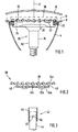
- Fig. 4 shows schematically a circuit arrangement according to an embodiment of the invention.
- Block 114 shows a circuit unit of an embodiment of the light emitting device according to the invention, consisting of mains input 103, rectifier 108, current limiting circuit 106, diode D, LED string 102, capacitance C1, capacitance CN + 1 and resistor R4.
- the rectifier circuit 108 By the rectifier circuit 108, an AC voltage possibly applied to the mains input is converted into a DC voltage, which consequently lies between the points 118 and 110.
- a bridge rectifier was used.
- LEDs (LED 1 to LED N) are connected in series with Zener diodes (ZD 1 to ZD N) connected in anti-parallel and capacitors (C 2 to C N) in parallel.
- each LED (LED 1 to LED N) has a capacitor (C2 to CN) connected in parallel and four LEDs each (LED 1 to LED N) has a Zener diode (ZD1 to ZD N) switched in anti-parallel.
- the forward voltage of the LEDs (LED 1 to LED N) in each case about 3.5 volts, 31 diodes were arranged in series.
- the breakdown voltage of the Zener diode (ZD 1 to ZD N) is higher than the sum of the forward voltages of the respective anti-parallel bridged LEDs (LED 1 to LED N). As a result, the flow of current through the zener diode (ZD1 to ZD N) is guaranteed if in the antiparallel bridged light emitting diodes (LED 1 to LED N) whose leads or their solder joints is a defect.
- the LEDs typically have, depending on the wavelength, a forward voltage of 2 to 4 V and z. B. selected with a rated current of 50 mA.
- the maximum allowable power dissipation of the zener diodes must be at least as high as the product of zener voltage and rated current through the LEDs.
- the diode D is in the forward direction between the rectifier circuit 108, d. H. the potential 108, and the LED string 102, d. H. the potential 104.
- the current limiting circuit of an embodiment of the light emitting device is shown. It is realized by an NPN transistor and the resistors R1, R2 and R3. The resistors R1 and R2 are connected in series between the potentials 118 and 110. The transistor T1 is connected with its base to the potential between the resistors R1 and R2.
- the emitter of the transistor T1 is connected to the potential 110.
- the collector of the transistor T1 is connected to the potential 104 via the resistor R3 and the LED string 102 connected therewith in series from the LEDs LED1 to LEDN.
- the base voltage is set, which is determined by the characteristic of the transistor, the collector current.
- the resistor R 1 is rated at approximately 100 kOhm
- the resistor R 2 at approximately 10 kOhm
- the resistor R3 at approximately 100 ohm.
- the transistor type MPSA 42 is used.
- the current-limiting circuit can be constructed, for example, from a MOS-FET transistor. In both cases described, the current limitation is achieved by the resistor R3.
- the transistor fulfills the function of the electronic switch.
- the described circuit can be constructed equivalently by means of a pnp bipolar transistor.
- its emitter is connected to the potential (104) of the anode of the diode (D) whose collector is connected via the LED strand (102) to the opposite mains voltage potential and its base connected to the potential of the mains voltage.
- the capacitance C1 is connected in parallel with the LED string 102 between the potentials 104 and 110.
- the capacitor C1 serves to smooth the half-waves of the rectified AC voltage, so that the LEDs are supplied with a quasi-continuous DC voltage.
- the capacitor CN + 1 is connected in parallel with the LED string 102 between the potentials 118 and 110. If the circuit is connected to the mains voltage, the capacitance C N + 1 ensures that the voltage divider 12 at the base of the transistor T1 between the peaks of the half-waves is supplied approximately with the peak voltage. This ensures that the transistor T1 between the tips of the half-waves turns on and the LEDs can light, since they are also powered by the capacitor C1 with power.
- the capacitor C1 is connected in parallel Discharge resistor R 4 provided and the diode D separates the voltage divider of the base of the transistor T1 from the potential 104 of the capacitor C 1, whereupon the transistor blocks the flow of current through the diodes.
- the circuit shown in block 116 corresponds exactly to the circuit described in block 114 and is constructed from the mains input redundant to the circuit described above.
- the circuit drawn in FIG. 5 differs from the circuit shown in FIG. 4 only in the following respect:
- the embodiment of FIG. 5 has a Stromeinlessnessge Surprise.
- the drive is realized by the resistor R1 and the directionally poled diode Dref.
- the base voltage of the transistor T1 is tapped from the diode Dref.
- the sum of the voltage drop across R13 and the voltage drop across the base-emitter path of T1 corresponds to the voltage across diode Dref. Since the voltage drop across the diode Dref largely independent of the mains voltage, thus the current through resistor R13 is independent of this, whereby the current through the LEDs is largely independent of the mains voltage.
- the resistor R13 should be dimensioned such that the quotient of the voltage across diode Dref minus voltage across the base-emitter path through the value of the resistor R13 substantially results in the rated current of the LEDs.
- An npn bipolar transistor T1 should be selected so that the mains voltage may be applied via the Kol Stammor-emitter path, and that the set current through the LEDs may flow over the collector-emitter path.
- the diode Dref can be realized by a diode or LED polarized in the direction of flux or by a zener diode which is poled in reverse direction.
- the transistor T1 can also be realized by a field effect transistor. To generate a constant current, a constant current diode can also be used.
- the diode Dref and resistor R1 can also be replaced by a reference voltage source.
- the transistor has function in the Stromeinlessnessge Saw and afterglow suppression.
- the described circuit can be constructed equivalently by means of a pnp bipolar transistor.
Abstract
Description
Gegenstand der Erfindung ist eine Lichtabgabeeinrichtung, insbesondere Verkehrssignal-Lichtabgabeeinrichtung, die mit Leuchtdioden (= LEDs) aufgebaut ist,
aufweisend folgende Merkmale:
- (a) die Lichtabgabeeinrichtung weist mindestens einen Strang auf, in dem eine Vielzahl von LEDs in Serie geschaltet ist;
- (b) der LED-Strang ist ohne Spannungkonversion und ohne Pulsmodulation im Wesentlichen an eine Netzspannung von mindestens 110 V anschließbar;
- (c) der LED-Strang ist über eine Strombegrenzungseinrichtung an die Netzspannung anschließbar; und
- (d) eine Einrichtung zum Unterdrücken des Nachleuchtens der LEDs ist vorgesehen.
having the following features:
- (A) the light emitting device has at least one strand in which a plurality of LEDs are connected in series;
- (b) the LED string can be connected without voltage conversion and without pulse modulation essentially to a mains voltage of at least 110 V;
- (C) the LED string is connected via a current limiting device to the mains voltage; and
- (d) means for suppressing the afterglow of the LEDs is provided.
Eine Lichtabgabeeinrichtung dieser Art mit den Merkmalen (a), (b), (c) ist aus
Bei der erfindungsgemäßen Lichtabgabeeinrichtung ist die Stromversorgung hinsichtlich Herstellungskosten, Zuverlässigkeit und Platzbedarf optimiert.In the light emitting device according to the invention, the power supply is optimized in terms of manufacturing costs, reliability and space requirements.
Vorzugsweise sind der LED-Strang und die strombegrenzende Schaltung über eine gleichrichtende Schaltung an die Netzspannung angeschlossen. Die gleichrichtende Schaltung kann insbesondere mit einer Diode oder mit einer Brückenschaltung aus Dioden realisiert sein.Preferably, the LED string and the current limiting circuit are connected via a rectifying circuit to the mains voltage. The rectifying circuit can be realized in particular with a diode or with a bridge circuit of diodes.
Vorzugsweise ist mindestens eine Kapazität in Parallelschaltung zu der gleichgerichteten Netzspannung und zu dem LED-Strang mit Strombegrenzungseinrichtung angeordnet. Dadurch wird erreicht, dass die LEDs näherungsweise mit Gleichstrom betrieben werden. Im Gleichstrombetrieb kann der vom Hersteller spezifizierte Nennstrom eingehalten werden. Die Speicherfunktion der parallel geschalteten Kapazität kann auch durch eine in Serie geschaltete Induktivität erreicht werden.Preferably, at least one capacitor is arranged in parallel with the rectified mains voltage and with the LED string with current-limiting device. This ensures that the LEDs are operated approximately with direct current. In DC operation, the rated current specified by the manufacturer can be maintained. The memory function of the parallel-connected capacitance can also be achieved by a series-connected inductor.
Ein Nachleuchten der LEDs kann aufgrund der in der zuvor genannten Kapazität gespeicherten Ladung entstehen, wenn diese nach Abschalten der Netzspannung über die LEDs abfließt. Ein Nachleuchten ist insbesondere bei blinkenden Lichtabgabeeinrichtungen störend. Eine Nachleuchtunterdrückung stellt sicher, dass nach Abschalten der Netzspannung die in der genannten Kapazität gespeicherte Ladung nicht über die LEDs abfließt. Dadurch ist sichergestellt, dass nach Abschalten der Netzspannung von der Lichtabgabeeinrichtung kein Licht mehr abgegeben wird.An afterglow of the LEDs may arise due to the charge stored in the aforementioned capacity when it drains off after switching off the mains voltage via the LEDs. Afterglow is particularly annoying with flashing light emitting devices. Afterglow suppression ensures that, after switching off the mains voltage, the charge stored in the stated capacity does not drain off via the LEDs. This ensures that after switching off the mains voltage from the light emitting device no light is emitted.
Vorzugsweise weist die Nachleuchtunterdrückung zwischen der gleichrichtenden Schaltung und der zuvor genannten Kapazität eine in Flußrichtung gepolte Diode auf. Der LED-Strang ist an der Anode dieser Diode angeschlossen. In Serie zu dem LED-Strang befindet sich ein elektronischer Schalter mit mindestens einem Steuereingang, wobei mindestens ein Steuereingang des elektronischen Schalters an die Netzspannung angeschlossen ist. Die Diode stellt sicher, dass nach Abschalten der Netzspannung kein Strom an den Steuereingang des elektronischen Schalters fließen kann und dass der genannte Steuereingang des elektronischen Schalters vom Potential dieser Kapazität getrennt ist. Somit unterbricht der elektronische Schalter den Stromfluß durch den LED-Strang.Preferably, the afterglow suppression between the rectifying circuit and the aforementioned capacitance has a forward-biased diode. The LED string is connected to the anode of this diode. In series with the LED string is an electronic switch with at least one control input, wherein at least one control input of the electronic switch is connected to the mains voltage. The diode ensures that, after switching off the mains voltage, no current can flow to the control input of the electronic switch and that said control input of the electronic switch is disconnected from the potential of this capacitor. Thus, the electronic switch interrupts the flow of current through the LED string.
Vorzugsweise weist der elektronische Schalter einen Transistor auf, dessen Kollektor über den LED-Strang an das Potential der Anode der zuvor genannten Diode angeschlossen ist, dessen Emitter an dem dazu entgegengesetzten Netzspannungspotential angeschlossen ist, und dessen Basis an das Potential der Netzspannung angeschlossen ist. Da nach Abschalten der Netzspannung an der Basis des Transistors kein Potential mehr anliegt, sperrt dieser den Stromfluß durch die LEDs.Preferably, the electronic switch has a transistor whose collector is connected via the LED string to the potential of the anode of the aforementioned diode whose emitter is connected to the opposite mains voltage potential, and whose base is connected to the potential of the mains voltage. Since after switching off the mains voltage at the base of the transistor no potential is applied, this blocks the flow of current through the LEDs.
Vorzugsweise ist in der Lichtabgabeeinrichtung mindestens ein Bauelement vorgesehen, das Funktion sowohl in der Strombegrenzungseinrichtung als auch in der Nachleuchtunterdrückung hat. Ein weiter unten beschriebenes Ausführungsbeispiel wird dies noch weiter verdeutlichen. Dadurch kann die Lichtabgabeeinrichtung kostengünstiger, platzsparender und zuverlässiger aufgebaut werden.Preferably, at least one component is provided in the light emitting device, which has function both in the current limiting device and in the afterglow suppression. An embodiment described below will illustrate this even further. As a result, the light emitting device can be built more cost-effective, space-saving and reliable.
Vorzugsweise ist zu der Kapazität mindestens ein Widerstand in Parallelschaltung angeordnet. Der Widerstand entlädt die Kapazität bei Abschalten der Netzspannung, wodurch ein Nachleuchten der LEDs verhindert wird. Vorzugsweise ist zwischen der Kapazität und dem Eingang der Strombegrenzungseinrichtung mindestens eine Diode geschaltet. Die Diode stellt sicher, dass nach Abschalten der Netzspannung kein Strom an die Ansteuerung der Strombegrenzungseinrichtung fließen kann und dass die Ansteuerung der Strombegrenzungseinrichtung vom Potential der Kapazität getrennt ist. Auch dies verhindert das Nachleuchten der LEDs.Preferably, at least one resistor is connected in parallel to the capacitance. The resistor discharges the capacitance when the mains voltage is switched off, which prevents the LEDs from flashing. Preferably, at least one diode is connected between the capacitance and the input of the current-limiting device. The diode ensures that after switching off the mains voltage no current can flow to the control of the current limiting device and that the control of the current limiting device is separated from the potential of the capacitance. This also prevents the afterglow of the LEDs.
Vorzugsweise ist den LEDs des LED-Strangs mindestens eine Kapazität parallel geschaltet, wobei jede Kapazität mindestens einer LED parallel geschaltet ist. Dadurch kann verhindert werden, dass eventuelle Spannungsspitzen die LEDs beschädigen. Es sind Ausführungsformen möglich, bei denen jeder LED eine Kapazität parallel geschaltet ist, oder auch Ausführungsformen, bei denen Gruppen von LEDs oder sogar allen LEDs eine Kapazität parallel geschaltet ist.Preferably, at least one capacitance is connected in parallel with the LEDs of the LED string, wherein each capacitance of at least one LED is connected in parallel. This can prevent any voltage surges from damaging the LEDs. Embodiments are possible in which each LED has a capacitance connected in parallel, or also embodiments in which groups of LEDs or even all LEDs have a capacitance connected in parallel.
Da LEDs eine Vorwärtsspannung im Bereich von wenigen Volt haben, war es - bei gewünschtem Anschluß an eine Netzspannung - bisher üblich, eine Spannungskonversion, typischerweise mit einem Transformator, vorzusehen. Verglichen mit den meisten Schaltungs-Bauelementen sind Transformatoren voluminös und schwer. Außerdem war es bisher üblich, die Stromversorgungsschaltung einer LED-Anordnung örtlich separiert von der LED-Anordnung vorzusehen. Schließlich hat man bisher üblicherweise die Leiterplatte, welche eine Mehrzahl von LEDs trägt, z.B. durch Schrauben an derjenigen Vorrichtung angebracht, in welcher die Lichtabgabeeinrichtung ihren Dienst versehen soll.Since LEDs have a forward voltage in the range of a few volts, it has hitherto been customary, with a desired connection to a mains voltage, to provide a voltage conversion, typically with a transformer. Compared to most circuit components, transformers are bulky and heavy. Moreover, it has been customary to provide the power supply circuit of an LED array locally separated from the LED array. Finally, the circuit board which carries a plurality of LEDs, e.g. attached by screws to that device in which the light emitting device to provide their service.
Vorzugsweise weist die Lichtabgabeeinrichtung folgende Merkmale auf:
- (a) einen Tragkörper, der einen Anbringungsbereich zum Haltern der Lichtabgabeeinrichtung in einem Sockel unter Stromzuführung und einen Lichtabgabebereich mit LEDs aufweist;
- (b) und eine Leiterplatte oder eine sandwichartige Leiterplattenanordnung, wobei die LEDs und die Bauelemente einer Schaltung, die ohne Spannungskonversion den Anschluß der Lichtabgabeeinrichtung an eine Netzspannung von mindestens 110 V erlaubt, an der Leiterplatte oder der sandwichartigen Leiterplattenanordnung angebracht sind.
- (A) a support body having a mounting portion for supporting the light emitting device in a socket under power supply and a light emitting area with LEDs;
- (b) and a printed circuit board or a sandwich-type printed circuit board assembly, wherein the LEDs and the components of a circuit, without voltage conversion, the connection of the light emitting device to a mains voltage of at least 110 V allowed, attached to the printed circuit board or the sandwich-type printed circuit board assembly.
Diese Lichtabgabeeinrichtung zeichnet sich dadurch aus, dass sie besonders rationell und kostengünstig herstellbar ist und besonders problemlos in die Vorrichtung eingesetzt werden kann, in welcher sie ihren Dienst versehen soll. Die Stromversorgung ohne Spannungskonversion führt zu einem leichten, kleinen Aufbau mit besonders geringem Ausfallrisiko.This light emitting device is characterized by the fact that it is particularly efficient and inexpensive to produce and can be used particularly easily in the device in which they should provide their service. The power supply without voltage conversion leads to a light, small structure with a particularly low risk of failure.
Wenn, wie bevorzugt, der Anbringungsbereich des Tragkörpers in eine gängige Schraubfassung oder eine gängige Steckfassung oder eine gängige Bajonettfassung, wie sie insbesondere für Glühlampen gängig sind, paßt, gestaltet sich das Einsetzen der Lichtabgabeeinrichtung in die Vorrichtung, in welcher sie ihren Dienst versehen soll, besonders einfach. Außerdem hat man eine perfekte "Umrüstlösung" vor sich, d.h. die Möglichkeit des problemlosen Austauschs einer bisher eingesetzten Glühlampe gegen eine erfindungsgemäße Lichtabgabeeinrichtung.If, as preferred, the mounting portion of the support body in a common screw socket or a common jack or a conventional bayonet mount, as they are in particular for incandescent lamps fits, the insertion of the light emitting device in the device in which they should provide their service, especially easy. In addition, one has a perfect "retrofit solution" in front of him, i. the possibility of easily exchanging a previously used incandescent lamp for a light emitting device according to the invention.
Mit "Netzspannung" ist vorzugsweise eine jeweilige Haushalts-Netzspannung gemeint. In vielen Ländern beträgt die Haushalts-Netzspannung 230 V oder 110 V. Die erfindungsgemäße Lichtabgabeeinrichtung kann jedoch auch für eine Netzspannung ausgelegt werden, die höher als übliche Haushalts-Netzspannungen ist, wenn z.B. Verkehrssignalanlagen mit einer höheren Netzspannung betrieben werden.By "mains voltage" is preferably meant a respective household mains voltage. However, in many countries the household mains voltage is 230V or 110V. However, the light emitting device of the present invention may be designed for a mains voltage higher than usual domestic mains voltages, e.g. Traffic signal systems are operated with a higher mains voltage.
Der Begriff "Verkehrssignal-Lichtabgabeeinrichtung" soll sämtliche Lichtabgabeeinrichtungen umfassen, durch die im Verkehr Information gegeben wird. Konkret seien zuerst Lichtabgabeeinrichtungen in Straßenverkehrsampeln genannt, wobei im weiteren Sinne insbesondere auch auf Lichtsignal-Verkehrszeichen, leuchtende Wegweiser, leuchtende Symbole wie Pfeilsymbole und vieles Ähnliche mehr hingewiesen wird. Erfindungsgemäße Verkehrssignal-Lichtabgabeeinrichtungen können insbesondere beim Straßenverkehr, beim Schienenverkehr (z.B. Signale an Schienenstrecken), Schiffsverkehr und Luftfahrtverkehr (z.B. auf Flughäfen) eingesetzt werden. Ganz besonders hingewiesen wird auf die Möglichkeit des Einsatzes als Landebahnbefeuerung auf Flughäfen, wo es sich einerseits um eine Verkehrssignal-Lichtabgabeeinrichtung im weitesten Sinne handelt (Information an den Flugzeugführer über die Begrenzungen der Landebahn), andererseits aber auch um eine Beleuchtung. Hinausgehend über den angesprochenen Bereich der Verkehrssignale ist die erfindungsgemäße Lichtabgabeeinrichtung insbesondere einsetzbar im gesamten Gebiet der Verkehrstechnik. Hierüber hinausgehend ist die erfindungsgemäße Lichtabgabeeinrichtung einsetzbar auf dem gesamten Gebiet der Beleuchtung. Besonders seien genannt die Straßenbeleuchtung, die Garagenbeleuchtung, die Gebäudebeleuchtung, die Bürobeleuchtung, die Wohnungsbeleuchtung.The term "traffic signal light emitting device" is intended to include all light emitting devices that provide information in the traffic. Concretely, first of all light emitting devices are called in traffic lights, which in the broader sense in particular also light signal traffic signs, luminous signposts, luminous symbols such as arrow symbols and much more similar is pointed out. Traffic signal light emission devices according to the invention can be used in particular for road traffic, rail traffic (eg signals on rail routes), shipping traffic and aviation traffic (eg at airports). Particular attention is drawn to the possibility of use as a runway lighting at airports, where on the one hand is a traffic signal light emitting device in the broadest sense (information to the pilot on the boundaries of the runway), on the other hand, but also to a lighting. Going beyond the addressed area of the traffic signals, the light-emitting device according to the invention can be used in particular in the entire field of traffic engineering. Beyond this, the light-emitting device according to the invention can be used in the entire field of illumination. Especially the street lighting, the garage lighting, the building lighting, the office lighting, the residential lighting are mentioned.
In Relation zu Lichtabgabeeinrichtungen, die auf dem Funktionsprinzip einer Glühlampe beruhen, zeichnen sich LED-Lichtabgabeeinrichtungen durch sehr viel höhere Lebensdauer und durch sehr viel geringeren Stromverbrauch aus. Gerade bei Verkehrssignal-Lichtabgabeeinrichtungen führt die sehr viel höhere Lebensdauer dazu, dass erhebliche Kosten für die Wartung und das häufige Auswechseln von Glühlampen eingespart werden.In relation to light emitting devices, which are based on the principle of operation of a light bulb, LED light emitting devices are characterized by much longer life and much lower power consumption. Especially with traffic signal light emitting devices, the much longer life means that significant costs for maintenance and frequent replacement of incandescent lamps can be saved.
Vorzugsweise sind die LEDs in ihrem Abstand von dem Anbringungsbereich des Tragkörpers so positioniert, dass ihre Lichtabgabe weitgehend dem von einem Reflektor reflektierten Licht einer Glühlampe einer gängigen Verkehrsampel äquivalent ist.Preferably, the LEDs are positioned in their distance from the mounting region of the support body so that their light output is largely equivalent to the reflected light from a reflector of a light bulb of a common traffic light equivalent.
Eine übliche Verkehrsampel enthält übereinander eine Quelle für grünes Signallicht, eine Quelle für gelbes Signallicht und eine Quelle für rotes Signallicht. Üblicherweise ist bei jeder dieser Quellen eine weiße Glühlampe vorgesehen, die mit einem Reflektor zusammenwirkt. Das durch den Reflektor nach vorn abgestrahlte Licht tritt durch eine farbige (grün oder gelb oder rot) Abschlußscheibe nach außen aus. Die erfindungsgemäße Verkehrssignal-Lichtabgabeeinrichtung kann so ausgebildet sein, dass ihr LED-Feld eine Lichtabgabe äquivalent der bisherigen Ausführungsform mit Glühlampe und Reflektor ergibt. Erfindungsgemäß ist festgestellt worden, dass die optimale Positionierung hinsichtlich des Abstands von dem Anbringungsbereich des Tragkörpers (was zugleich auch optimale Positionierung hinsichtlich des Abstands von der Abschlußscheibe bedeutet) wichtig ist. Wenn das LED-Feld zu weit von der Abschlußscheibe entfernt ist, wird weniger als die optimale Lichtstärke erreicht. Wenn das LED-Feld zu nah an der Abschlußscheibe positioniert ist, wird nicht die optimale Homogenität der Lichtabgabe für das Verkehrssignal erreicht.A common traffic light contains one above the other a source of green signal light, a source of yellow signal light and a source of red signal light. Usually, a white incandescent lamp is provided in each of these sources, which cooperates with a reflector. The light emitted by the reflector to the front exits through a colored (green or yellow or red) lens to the outside. The traffic signal light emitting device according to the invention can be designed so that its LED field gives a light output equivalent to the previous embodiment with incandescent lamp and reflector. According to the invention, it has been found that the optimum positioning in terms of the distance from the mounting region of the support body (which also means optimal positioning with respect to the distance from the lens) is important. If the LED field is too far away from the lens, less than the optimum light intensity is achieved. If the LED box is too close to the lens is positioned, the optimal homogeneity of the light output for the traffic signal is not achieved.
Vorzugsweise besteht bei der erfindungsgemäßen Lichtabgabeeinrichtung der Tragkörper mit Ausnahme von Teilen des Anbringungsbereichs (insbesondere solchen, die der Stromführung dienen), aus Kunststoff. Ein Kunststoff-Tragkörper läßt sich in den unterschiedlichsten Formen problemlos und kostengünstig fertigen. Häufig wird der Tragkörper eine kegelstumpfartige Grundform haben, wobei sich der Anbringungsbereich an dem durchmesserkleineren Ende des Tragkörpers befindet und die Leiterplatte bzw. die sandwichartige Leiterplattenanordnung sich an dem durchmessergrößeren Ende des Tragkörpers befindet. Hierbei kommt es selbstverständlich nicht auf eine exakte Geometrie eines Kegelstumpfs an; der Tragkörper stellt vielmehr einen Übergang von einem Querschnittsflächen-kleineren Endbereich (= Anbringungsbereich) zu einem Querschnittsflächen-größeren Endbereich (= Lichtabgabebereich mit LEDs) bereit. In vielen Fällen und damit vorzugsweise hat der Tragkörper eine Konfiguration mit im wesentlichen kreisförmigem Querschnitt, wobei sich der Querschnitt beim Fortschreiten in Längsrichtung des Tragkörpers normalerweise ändert. Wenn die erfindungsgemäße Lichtabgabeeinrichtung für eine Verkehrsampel vorgesehen ist, hat die Leiterplatte oder die Leiterplattenanordnung vorzugsweise in Draufsicht einen Durchmesser, der im wesentlichen dem vorderen Enddurchmesser des Reflektors einer gängigen Verkehrsampel entspricht. Z.B. in Deutschland beträgt der vordere Enddurchmesser des Reflektors einer gängigen Verkehrsampel 200 mm oder, bei größeren Verkehrsampeln, 300 mm. Mit im wesentlichen derart großen Leiterplatten bzw. Leiterplattenanordnungen nutzt man die zur Verfügung stehende Lichtabgabefläche optimal aus und erreicht optimale Homogenität der Lichtabgabe.Preferably, in the case of the light-emitting device according to the invention, the support body, with the exception of parts of the attachment region (in particular those which serve to conduct current), consists of plastic. A plastic support body can be easily and inexpensively manufactured in a variety of forms. Frequently, the support body will have a frustoconical basic shape, wherein the mounting portion is located at the smaller diameter end of the support body and the circuit board or the sandwich-like circuit board assembly is located at the larger diameter end of the support body. Of course, this does not depend on an exact geometry of a truncated cone; rather, the support body provides a transition from a cross-sectional area-smaller end area (= mounting area) to a cross-sectional area-larger end area (= light-emitting area with LEDs). In many cases, and thus preferably, the support body has a configuration with a substantially circular cross-section, wherein the cross-section normally changes as it progresses in the longitudinal direction of the support body. When the light emitting device according to the invention is intended for a traffic light, the printed circuit board or the printed circuit board arrangement preferably has a diameter in plan view which substantially corresponds to the front end diameter of the reflector of a common traffic light. For example, In Germany, the front end diameter of the reflector of a standard traffic light is 200 mm or, for larger traffic lights, 300 mm. With essentially such large printed circuit boards or printed circuit board arrangements, the available light emission surface is optimally utilized and optimum homogeneity of the light output is achieved.
Vorzugsweise ist der Tragkörper vor den LEDs mit einer lichtdurchlässigen Abschlußplatte versehen. Die Abschlußplatte kann zum schützenden Abschließen z.B. gegen Feuchtigkeit und Schmutz vorgesehen sein. Man kann die Abschlußplatte aber auch zur optischen Beeinflussung der Lichtabgabe der LEDs einsetzen, z.B. zum Fokussieren, zum Erzeugen im wesentlichen paralleler Lichtstrahlen oder als Streuscheibe.Preferably, the support body is provided in front of the LEDs with a translucent end plate. The end plate may be provided for protective completion, for example against moisture and dirt. But you can also use the end plate for the optical influence of the light output of the LEDs, for example, for focusing, for generating substantially parallel light rays or as a diffuser.
Vorzugsweise weist der Tragkörper einen Anlagering zur Anlage gegen einen Widerlagerbereich einer Vorrichtung, in welche die Lichtabgabeeinrichtung eingesetzt werden soll, auf. Hierdurch erreicht man eine zusätzliche Lagestabilisierung der Lichtabgabeeinrichtung im gehalterten Zustand, so dass man zur Lagefixierung nicht ausschließlich auf das Haltern in dem Sockel angewiesen ist.Preferably, the support body has an abutment ring for abutment against an abutment region of a device in which the light-emitting device is to be used. This achieves an additional position stabilization of the light-emitting device in the retained state, so that one does not rely solely on the holders in the base for fixing the position.
Vorzugsweise weist der Tragkörper einen längenverstellbaren Bereich auf, durch dessen Verstellung sich die Positionierung der LEDs relativ zu dem Anbringungsbereich des Tragkörpers einstellen läßt. Weiter vorn ist bereits darauf hingewiesen worden, dass es vorteilhaft sein kann, die LEDs an einer bestimmten Stelle bezogen auf die Längsrichtung der optischen Achse der Lichtabgabeeinrichtung zu positionieren (insbesondere so zu positionieren, dass die Lichtabgabe der LEDs weitgehend dem von einem Reflektor reflektierten Licht einer Glühlampe einer gängigen Verkehrsampel äquivalent ist). Damit man eine gewünschte günstige Positionierung der LEDs auf eine einfache Weise einstellen kann, ist der genannte längenverstellbare Bereich vorgesehen. Der längenverstellbare Bereich kann insbesondere durch einen teleskopartig ausgebildeten Bereich verwirklicht sein.Preferably, the support body has a length-adjustable range, can be adjusted by the adjustment of the positioning of the LEDs relative to the mounting region of the support body. It has already been pointed out in the foregoing that it may be advantageous to position the LEDs at a specific location relative to the longitudinal direction of the optical axis of the light emitting device (in particular to position the light output of the LEDs to a large extent to the light reflected by a reflector) Incandescent lamp is a standard traffic light equivalent). In order to be able to set a desired favorable positioning of the LEDs in a simple manner, said length-adjustable region is provided. The length-adjustable region can be realized in particular by a telescopically formed region.
Die Vielzahl der in einem Strang in Serie geschalteten LEDs kann so hoch gewählt werden, dass sich die Summe der Durchlassspannungen dieser LEDs in der Nähe der Netzspannung oder eines abgegriffenen Teils der Netzspannung befindet; hierdurch läßt sich die Verlustleistung in anderen Schaltungsteilen verringern. Durch Betreiben der LEDs ohne Pulsmodulation, mit Gleichstrom, kann der vom Hersteller spezifizierte Nennstrom durch die LEDs eingehalten werden. Dadurch ist sichergestellt, dass die vom LED-Hersteller spezifizierte Mindest-Lebensdauer der LEDs nicht durch Pulsmodulation beeinträchtigt wird.The plurality of LEDs connected in series in a string can be selected to be so high that the sum of the forward voltages of these LEDs is in the vicinity of the mains voltage or a tapped part of the mains voltage; This can reduce the power loss in other circuit parts. By operating the LEDs without pulse modulation, with direct current, the nominal current specified by the manufacturer can be maintained by the LEDs. This ensures that the minimum LED life specified by the LED manufacturer is not affected by pulse modulation.
Die Zener-Spannung der betreffenden Zener-Diode kann so berechnet werden, dass sie höher ist, als die Durchlassspannung der LED, mit der die Zener-Diode antiparallel geschaltet ist. Im Fall einer Unterbrechung des Stromflusses durch die LED ist der Stromfluß zu den weiteren LEDs des LED-Strangs gewährleistet. Durch diese Beschaltung wird erreicht, dass z.B. im Fall einer defekten LED, einer defekten Leiterbahn oder einer defekten Lötstelle, die LEDs, die nicht von der Zener-Diode antiparallel geschaltet sind, weiterleuchten. Wenn eine Zener-Diode mit mehreren, ihrerseits in Serie geschalteten LEDs antiparallel geschaltet ist, kann man bei der obigen Berechnung die Summe der Durchlassspannungen der betreffenden LEDs ansetzen. Vorzugsweise werden mindestens zwei LEDs von einer Zener-Diode überbrückt, stärker bevorzugt mindestens drei LEDs, noch stärker bevorzugt mindestens 4 LEDs; ganz besonders bevorzugt ist es, wenn drei bis acht LEDs überbrückt sind.The Zener voltage of the respective Zener diode can be calculated to be higher than the forward voltage of the LED with which the Zener diode is connected in anti-parallel. In the case of an interruption of the current flow through the LED, the current flow is ensured to the other LEDs of the LED string. By this wiring is achieved that, for example, in the case of a defective LED, a defective trace or a defective solder joint, the LEDs that are not connected in anti-parallel from the Zener diode continue lighting. If a zener diode is connected in anti-parallel with several, in turn connected in series LEDs, the sum of the forward voltages of the respective LEDs can be set in the above calculation. Preferably, at least two LEDs are bridged by a zener diode, more preferably at least three LEDs, even more preferably at least four LEDs; It is particularly preferred if three to eight LEDs are bridged.
Wenn vorstehend gesagt worden ist, dass der LED-Strang an eine Netzspannung von mindestens 110 V angeschlossen ist, soll dies naturgemäß nicht bedeuten, dass der LED-Strang direkt an die Netzspannung angeschlossen ist. In aller Regel sind zwischengeschaltete Schaltungsglieder vorhanden. Der LED-Strang und die Strombegrenzungseinrichtung können indirekt an die Netzspannung von mindestens 110 V angeschlossen sein. Die zwischengeschalteten Schaltungsglieder, z. B. ein Spannungsteiler, können bewirken, dass an dem LED-Strang und der Strombegrenzungseinrichtung nur eine Teil-Netzspannung anliegt. Die Möglichkeit des indirekt Angeschlossen-Seins gilt auch für die anderen Stellen der vorliegenden Anmeldung, wo von "angeschlossen ist" gesprochen wird.If it has been stated above that the LED string is connected to a mains voltage of at least 110 V, this naturally does not mean that the LED string is connected directly to the mains voltage. As a rule, intermediate circuit elements are present. The LED string and the current limiting device can be connected indirectly to the mains voltage of at least 110V. The intermediate circuit elements, for. As a voltage divider, can cause the fact that only a partial mains voltage is applied to the LED string and the current limiting device. The possibility of being indirectly connected is also valid for the other parts of the present application, where the term "connected" is used.
Vorzugsweise weist die Strombegrenzungseinrichtung einen Widerstand auf. Man kann die Schaltung so ausbilden, dass an diesem Widerstand im Wesentlichen die Differenz aus der Netzspannung und der Spannung über den LED-Strang abfällt.Preferably, the current limiting device has a resistance. The circuit can be designed in such a way that essentially the difference between the mains voltage and the voltage across the LED string drops at this resistor.
Vorzugsweise weist die Strombegrenzungseinrichtung eine Stromeinprägeeinrichtung auf. Dadurch wird eine weitgehende Unabhängigkeit des Stroms durch die LEDs, und damit der Intensität der LEDs, von Schwankungen der Netzspannung erreicht. Außerdem wird optimale Lebensdauer der LEDs sichergestellt.The current-limiting device preferably has a current injection device. As a result, a substantial independence of the current through the LEDs, and thus the intensity of the LEDs, is achieved by fluctuations of the mains voltage. In addition, optimal life of the LEDs is ensured.
Vorzugsweise weist die Stromeinprägeeinrichtung einen Widerstand und eine Diode auf, die in Serie an die Netzspannung angeschlossen,sind, wobei der Widerstand am gleichen Potential der Netzspannung wie der LED-Strang angeschlossen ist, wogegen die Diode an dem dazu entgegengesetzen Potential der Netzspannung angeschlossen ist. Weiterhin weist diese Stromeinprägeeinrichtung einen Transistor auf, an dessen Basis das Potential zwischen dem Widerstand und der Diode anliegt, dessen Kollektor über den LED-Strang an dem genannten gleichen Potential der Netzspannung angeschlossen ist, und dessen Emitter über einen weiteren Widerstand an das dazu entgegengesetzte Potential der Netzspannung angeschlossen ist. Die Diode kann beispielsweise durch eine in Sperrrichtung gepolter Zener-Diode, eine in Flußrichtung gepolte Diode oder eine in Flußrichtung gepolte LED ausgeführt sein. Dadurch wird eine von der Netzspannung unabhängige Referenzspannung erzeugt. Die Summe aus der Basis-Emitter-Spannung und der Spannung über den am Emitter angeschlossenen, weiteren Widerstand ist bei dieser Beschaltung identisch mit der Spannung über die Diode. Da die Spannung über den am Emitter angeschlossenen, weiteren Widerstand im Wesentlichen von dem Strom über den LED-Strang abhängt, stellt sich ein konstanter Strom durch den LED-Strang ein.Preferably, the Stromeinprägeeinrichtung has a resistor and a diode connected in series to the mains voltage, wherein the resistor is connected to the same potential of the mains voltage as the LED string, whereas the diode is connected to the opposite potential of the mains voltage. Furthermore, this Stromeinprägeeinrichtung has a transistor at the base of which the potential between the resistor and the diode is applied, the collector via the LED strand to said the same potential of the mains voltage is connected, and whose emitter is connected via a further resistor to the opposite potential of the mains voltage. The diode can be embodied, for example, by a reversely poled Zener diode, a diode poled in the direction of flux, or a LED poled in the direction of flux. This generates a reference voltage independent of the mains voltage. The sum of the base-emitter voltage and the voltage across the further resistor connected to the emitter is identical to the voltage across the diode in this circuit. Since the voltage across the further resistor connected to the emitter essentially depends on the current across the LED string, a constant current is established through the LED string.
Der Strom über den LED-Strang kann über folgende Formel berechnet werden: ![]()
dabei bedeuten:
- ILED:
- Strom durch den LED-Strang;
- UD:
- Strom über die Diode;
- UBE:
- Spannung über die Basis-Emitter-Strecke des Transistors;
- RE:
- Wert des am Emitter angeschlossenen, weiteren Widerstands.
where:
- I LED:
- Current through the LED string;
- U D :
- Current through the diode;
- U BE :
- Voltage across the base-emitter path of the transistor;
- R E :
- Value of the additional resistor connected to the emitter.
Vorzugsweise sind die Anordnung der LEDs und die Stromversorgung der LEDs ab dem Netzeingang redundant. Selbst bei einem beliebigen Ausfall an irgendeiner Stelle der LEDs oder der Stromversorgung der LEDs ist immer noch eine Funktion der Lichtabgabeeinrichtung mit verringerter Lichtabstrahlung möglich. Aufgrund des sehr einfachen Aufbaus der erfindungsgemäßen Stromversorgung läßt sich der redundante Aufbau ohne wesentliche Mehrkosten und ohne wesentlichen zusätzlichen Platzbedarf realisieren. Es wird betont, dass es in bevorzugter Weiterbildung der Erfindung alternativ möglich ist, nur einen Teil von LED-Anordnung und Stromversorgung redundant auszuführen, also gleichsam mit der redundanten Ausführung ein Stück entfernt von dem Netzeingang zu beginnen.Preferably, the arrangement of the LEDs and the power supply of the LEDs are redundant from the mains input. Even with any failure at any point on the LEDs or powering the LEDs, a function of the light emitting device with reduced light output is still possible. Due to the very simple structure of the power supply according to the invention, the redundant structure can be realized without significant additional costs and without significant additional space requirements. It is emphasized that, in a preferred development of the invention, it is alternatively possible to perform only a part of the LED arrangement and the power supply redundantly, that is to say begin with the redundant embodiment a distance away from the power input.
Vorzugsweise sind die LEDs und die Stromversorgung der LEDs auf einer Leiterplatte oder einer sandwichartigen Leiterplattenanordnung angebracht. Es kommen auch flexible Leiterplatten in Betracht.Preferably, the LEDs and the power supply of the LEDs are mounted on a printed circuit board or a sandwich-type printed circuit board assembly. There are also flexible printed circuit boards into consideration.
Vorzugsweise sind die LEDs der redundanten LED-Stränge so auf der Leiterplatte oder der sandwichartigen Leiterplattenanordnung angeordnet, dass bei Ausfall eines redundanten Teils eine im wesentlichen homogene Lichtabgabe erreicht wird. Insbesondere können die LEDs der redundanten Stränge im wesentlichen alternierend angeordnet werden.The LEDs of the redundant LED strands are preferably arranged on the printed circuit board or the sandwich-type printed circuit board arrangement in such a way that a substantially homogeneous light output is achieved if one redundant part fails. In particular, the LEDs of the redundant strings can be arranged substantially alternately.
Vorzugsweise sind die LEDs der redundanten LED-Stränge so auf der Leiterplatte oder der sandwichartigen Leiterplattenanordnung angeordnet, dass bei Ausfall eines redundanten Teils eine derart nicht-homogene Lichtabgabe entsteht, dass der Ausfall für einen Betrachter erkennbar ist. Zum Beispiel kann man eine erste Gruppe von LEDs auf einem ersten Teil der Lichtabgabefläche anordnen und eine redundante, zweite Gruppe von LEDs auf einem zweiten Teil der Lichtabgabefläche anordnen, z. B. zwei Halbkreise. Jede der zwei Gruppen kann weiter unterteilt sein, so dass man z. B. vier Kreissektoren oder vier Streifen innerhalb eines Quadrats erhält.Preferably, the LEDs of the redundant LED strands are arranged on the printed circuit board or the sandwich-like printed circuit board assembly that such a non-homogeneous light output arises in the event of failure of a redundant part that the failure for a viewer is recognizable. For example, one may dispose a first group of LEDs on a first portion of the light emitting surface and place a redundant, second group of LEDs on a second portion of the light emitting surface, e.g. B. two semicircles. Each of the two groups can be subdivided further, so that z. B. receives four circular sectors or four stripes within a square.
Weiter oben ist bereits angesprochen worden, dass die redundante Auslegung die Funktion der Lichtabgabeeinrichtung, wenn auch mit verringerter Lichtabgabe, bei irgendeinem elektrischen Ausfall sicherstellt. Dies ist gerade auch bei Verkehrssignal-Lichtabgabeeinrichtungen von besonders großer Bedeutung.It has already been mentioned above that the redundant design ensures the function of the light emitting device, albeit with reduced light output, at any electrical failure. This is especially important in traffic signal light emitting devices of particular importance.
Bei entsprechender Ausführung, wie sie weiter oben als bevorzugte Ausführung angesprochen worden ist, läßt sich eine erfindungsgemäße Verkehrssignal-Lichtabgabeeinrichtung durch einfaches Austauschen anstelle einer Glühlampe einsetzen. Dabei ist die Ausführung vorzugsweise derart, dass der Reflektor einer gängigen Ampel in der Ampel verbleibt. Auch die vorhandene farbige Abschlußscheibe kann in der Ampel verbleiben.With appropriate design, as has been mentioned above as the preferred embodiment, a traffic signal light emitting device according to the invention can be used by simply replacing instead of a light bulb. In this case, the embodiment is preferably such that the reflector of a standard traffic light remains in the traffic light. The existing colored lens can also remain in the traffic light.
Bei erfindungsgemäßen Verkehrssignal-Lichtabgabeeinrichtungen sieht man vorzugsweise farbige LEDs vor, z.B. rote LEDs für ein rotes Ampelsegment, grüne LEDs für ein grünes Ampelsegment und gelbe LEDs für ein gelbes Ampelsegment. Andererseits kann man bei der Erfindung mit weißen LEDs arbeiten, und zwar nicht nur bei Verkehrssignal-Lichtabgabeeinrichtungen, sondern ganz besonders bei Beleuchtungen.In traffic signal light emitting devices according to the invention, colored LEDs are preferably provided, for example red LEDs for a red traffic light segment, green LEDs for a green traffic light segment and yellow LEDs for a yellow traffic light segment. On the other hand, one can work in the invention with white LEDs, not only in traffic signal light emitting devices, but especially in lighting.
Bei der Erfindung arbeitet man vorzugsweise ohne Impulsschaltung, um die LEDs an der Netzspannung zu betreiben.In the invention, it is preferable to operate without pulse switching to operate the LEDs on the mains voltage.
Es wird betont, dass zahlreiche Merkmale der Erfindung auch bei einer Lichtabgabeeinrichtung verwirklicht werden können, die nicht für Anschluß an eine Netzspannung von mindestens 110 V ausgelegt ist, sondern z.B. für eine proprietäre Spannung unterhalb von 110 V, vorzugsweise im Bereich von 24 bis 110 V.It is emphasized that numerous features of the invention can also be realized in a light emitting device which is not designed for connection to a mains voltage of at least 110 V, but for example for a proprietary voltage below 110 V, preferably in the range of 24 to 110 V. ,
Die Erfindung und bevorzugte Ausführungen der Erfindung werden nachfolgend anhand von zeichnerisch dargestellten Ausführungsbeispielen noch näher erläutert. Es zeigt:
- Fig. 1
- eine Verkehrssignal-Lichtabgabeeinrichtung, in Seitenansicht und teilweise im Längsschnitt;
- Fig. 2
- einen Teil einer Verkehrssignal-Lichtabgabeeinrichtung alternativer Ausführung, im Längsschnitt;
- Fig. 3
- einen Teil einer Verkehrssignal-Lichtabgabeeinrichtung alternativer Ausführung, im teilweisen Längsschnitt;
- Fig. 4
- ein Schaltbild für die LEDs und die Strombegrenzungseinrichtung für die LEDs bei einer Lichtabgabeeinrichtung.
- Fig. 5
- ein Schaltbild für die LEDs und die Strombegrenzungseinrichtung für die LEDs bei einer Lichtabgabeeinrichtung, wobei die Strombegrenzungseinrichtung durch eine Stromeinprägeeinrichtung realisiert ist.
- Fig. 1
- a traffic signal light emitting device, in side view and partially in longitudinal section;
- Fig. 2
- a part of a traffic signal light emitting device of alternative embodiment, in longitudinal section;
- Fig. 3
- a part of a traffic signal light emitting device of alternative embodiment, in partial longitudinal section;
- Fig. 4
- a circuit diagram for the LEDs and the current limiting device for the LEDs in a light emitting device.
- Fig. 5
- a circuit diagram for the LEDs and the current limiting device for the LEDs in a light emitting device, wherein the current limiting device is realized by a Stromeinprägeeinrichtung.
In Fig. 1 ist im Längsschnitt, der die optische Achse 2 enthält, ein Teil eines Ampelsegments (sei es grünes Ampelsegment, sei es gelbes Ampelsegment, sei es rotes Ampelsegment) dargestellt, und zwar ein vorderer Bereich eines Reflektors 4 und eine vordere, farbige Abschlußscheibe 6. Im weggeschnittenen, hinteren Bereich des Reflektors 4 trägt der Reflektor 4 eine Schraubfassung, in welche bei einem herkömmlichen Ampelsegment eine Glühlampe eingeschraubt ist. Der Reflektor 4 ist mit seinem vorderen Endbereich in einem Gehäuse des betreffenden Ampelsegments befestigt, wie Fig. 1 mit einem vorderen Endflansch 8 des Reflektors 4 und Achsen 10 von Befestigungsschrauben angedeutet.In Fig. 1, in longitudinal section, which contains the optical axis 2, a part of a traffic light segment (be it green traffic light segment, be it yellow traffic light segment, be red traffic light segment) is shown, namely a front portion of a reflector 4 and a front,
Die sonst bei einem Ampelsegment, welches mit einer Glühlampe betrieben wird, vorhandene Glühlampe ist herausgeschraubt worden, und statt dessen ist eine gezeichnete Verkehrssignal-Lichtabgabeeinrichtung 20 in die gleiche Fassung eingeschraubt worden. In ihrem vorderen Endbereich (oben in Fig. 1) vergrößert sich die Lichtabgabeeinrichtung 20 bis nahezu auf den Innendurchmesser des Reflektors 4 in seinem vorderen Endbereich. Dort ist ein Gummiring 22, gehaltert in einer umlaufenden Nut der Lichtabgabeeinrichtung 20, an der Lichtabgabeeinrichtung 20 angebracht. Der Außendurchmesser des Rings 22 und seine axiale Positionierung (optische Achse 2 = Längsmittelachse der Lichtabgabeeinrichtung 20) sind so abgestimmt, dass bei vollständigem Einschrauben der Lichtabgabeeinrichtung 20 in die nicht gezeichnete Schraubfassung der Ring 22 mit einem hinteren Endbereich seines Außenumfangs in Anlage von innen her an den Reflektor 4 kommt, wodurch die Lichtabgabeeinrichtung zusätzlich stabilisiert wird. Über die nicht gezeichnete Schraubfassung wird die Lichtabgabeeinrichtung 20 wie eine Glühlampe an eine Netzspannung von z.B. 110 V oder 230 V angeschlossen.The otherwise available in a traffic light segment, which is operated with an incandescent lamp bulb has been unscrewed, and instead a drawn traffic signal
In ihrem vorderen Endbereich (oben in Fig. 1) trägt die Lichtabgabeeinrichtung 20 eine Leiterplatte 24, die sich rechtwinklig zu der Achse 2 erstreckt. Die Leiterplatte 24 hat einen Außendurchmesser, der nur wenig kleiner ist als der größte Innendurchmesser des Reflektors 4. Auf der Vorderseite der Leiterplatte 24 ist eine Vielzahl von LEDs 30 angebracht. Auf der Rückseite der Leiterplatte 24 sind Schaltungsbausteine 32 angebracht. Ein Ausführungsbeispiel einer LED -Anordnung und einer Schaltung werden weiter unten noch beschrieben werden. An der jetzigen Stelle wird lediglich darauf hingewiesen, dass die Schaltung ohne Spannungskonversion und ohne Pulsmodulation den Betrieb der LEDs 30 an der Netzspannung ermöglicht.In its front end region (at the top in FIG. 1), the light-emitting
Die gezeichnete und beschriebene Verkehrssignal-Lichtabgabeeinrichtung 20 setzt sich somit zusammen aus einem - grob gesprochen - pilzförmigen Tragkörper 34 und der angesprochenen Leiterplatte 24 mit den daran angebrachten LEDs 30 und Schaltungs-Bauelementen 32. Der Tragkörper 34 besteht vorzugsweise aus Kunststoff und ist vorzugsweise durch Spritzgießen hergestellt. Der hintere Endbereich des Tragkörpers 34 mit dem Schraubgewinde stellt einen Anbringungsbereich zum Haltern der Lichtabgabeeinrichtung 20 dar; der vordere Endbereich des Tragkörpers 34, wo die Leiterplatte 24 gehaltert ist, stellt einen Lichtabgabebereich der Lichtabgabeeinrichtung 20 dar.The drawn and described traffic signal
Mit einer unterbrochenen Linie ist eine lichtdurchlässige Abschlußplatte 36 der Lichtabgabeeinrichtung 20 angedeutet, die optional vorhanden sein kann.With a broken line, a
In Fig. 2 ist eine Alternative veranschaulicht, bei der statt der Leiterplatte 24 von Fig. 1 eine vordere Leiterplatte 24 a und eine hintere Leiterplatte 24 b vorhanden sind. Die Leiterplatten 24 a und 24 b bilden eine sandwichartige Leiterplattenanordnung 38. Die vordere Leiterplatte 24 a trägt die LEDs 30 und Bauelemente 32 a die von der Schaltung her den LEDs 30 am sinnvollsten nahe benachbart positioniert werden (insbesondere Zener-Dioden und Kondensatoren, siehe Beschreibung einer Schaltung weiter unten). Die hintere Leiterplatte 24 b trägt die restlichen Bauelemente 32 b. Durch Steckverbinder 40 sind die Leiterplatten 24a und 24b elektrisch miteinander verbunden.In Fig. 2, an alternative is illustrated, in which instead of the
Fig. 3 veranschaulicht einen längenverstellbaren Bereich 42 eines Tragkörpers einer Lichtabgabeeinrichtung 20. Nach Art einer Teleskopverbindung ragt ein zylindrischer, hinterer Bereich 44 des Tragkörpers in einen etwas durchmessergrößeren, vorderen Bereich 46 des Tragkörpers hinein. An dem hinteren Bereich 44 ist ein radial nach außen ragender Stift 48 befestigt. Der Stift 48 wirkt mit einer Nut oder einem Schlitz 50 zusammen, der in dem vorderen, zylindrischen Bereich 46 in einem spiralförmigen Verlauf analog einem Gewindegang vorgesehen ist. Wenn man die Bereiche 44 und 46 gegeneinander verdreht, ändert sich die effektive Länge des Tragkörpers, gemessen in Richtung der Achse 2. Die Passung zwischen dem vorderen Bereich 46 und dem hinteren Bereich 44 ist so eng, dass sich eine einmal eingestellt Längeneinstellung nicht wieder von selbst verändert. Ggf. kann ein reibungserhöhender Zwischenring zwischen dem Bereich 46 und 44 vorgesehen sein. Der längenverstellbare Bereich 42 befindet sich in demjenigen Teil des Tragkörpers, der in Fig. 1 mit 52 bezeichnet ist.FIG. 3 illustrates a length-
Fig. 4 zeigt schematisch eine Schaltungsanordnung gemäß einer Ausführungsform der Erfindung.Fig. 4 shows schematically a circuit arrangement according to an embodiment of the invention.
Block 114 zeigt eine Schaltungseinheit einer Ausführungsform der erfindungsgemäßen Lichtabgabeeinrichtung, bestehend aus Netzeingang 103, Gleichrichter 108, strombegrenzender Schaltung 106, Diode D, LED-Strang 102, Kapazität C1, Kapazität CN+1 und Widerstand R4.
Durch die Gleichrichterschaltung 108 wird eine am Netzeingang eventuell anliegende Wechselspannung in eine Gleichspannung umgewandelt, die folglich zwischen den Punkten 118 und 110 anliegt. In der vorliegenden Ausführungsform wurde, ohne andere Ausführungsformen auszuschließen, ein Brückengleichrichter verwendet.By the
In Block 102 sind LEDs (LED 1 bis LED N) in Serie geschaltet, wobei Zener-Dioden (ZD 1 bis ZD N) antiparallel geschaltet und Kondensatoren (C 2 bis C N) parallel sind. In der vorliegenden Ausführungsform wurde, ohne andere Ausführungsformen auszuschließen, jeder LED (LED 1 bis LED N) ein Kondensator (C2 bis C N) parallel geschaltet und jeweils vier LEDs (LED 1 bis LED N) eine Zener-Diode (ZD1 bis ZD N) antiparallel geschaltet. In dieser Ausführungsform beträgt die Durchlassspannung der LEDs (LED 1 bis LED N) jeweils ca. 3,5 Volt, es wurden 31 Dioden in Serie angeordnet. Die Durchbruchspannung der Zener-Diode (ZD 1 bis ZD N) liegt höher als die Summe der Durchlassspannungen der jeweils antiparallel überbrückten Leuchtdioden (LED 1 bis LED N). Dadurch ist der Stromfluß über die Zener-Diode (ZD1 bis ZD N) gewährleistet, falls in den antiparallel überbrückten Leuchtdioden (LED 1 bis LED N), deren Zuleitungen oder deren Lötstellen ein Defekt entsteht.In
Die LEDs haben typischerweise, je nach Wellenlänge, eine Durchlassspannung von 2 bis 4 V und werden z. B. mit einem Nennstrom von 50 mA ausgewählt. Die maximal zulässige Verlustleistung der Zenerdioden muß mindestens so hoch sein wie das Produkt aus Zenerspannung und Nennstrom durch die LEDs.The LEDs typically have, depending on the wavelength, a forward voltage of 2 to 4 V and z. B. selected with a rated current of 50 mA. The maximum allowable power dissipation of the zener diodes must be at least as high as the product of zener voltage and rated current through the LEDs.
Die Diode D befindet sich in Durchlaßrichtung zwischen der Gleichrichterschaltung 108, d. h. dem Potential 108, und dem LED-Strang 102, d. h. dem Potential 104.The diode D is in the forward direction between the
In Block 106 ist die strombegrenzende Schaltung einer Ausführungsform der Lichtabgabeeinrichtung dargestellt. Sie ist durch einen npn-Transistor und die Widerständen R1, R2 und R3 realisiert. Die Widerstände R1 und R2 sind in Serie zwischen die Potentiale 118 und 110 geschaltet. Der Transistor T1 ist mit seiner Basis an das Potential zwischen den Widerständen R1 und R2 angeschlossen.In
Der Emitter des Transistors T1 ist an das Potential 110 angeschlossen. Der Kollektor des Transistors T1 ist über den Widerstand R3 und den damit in Serie geschalteten LED-Strang 102 aus den LEDs LED1 bis LEDN an das Potential 104 angeschlossen. Über die Widerstände R1 und R2 wird die Basisspannung eingestellt, wodurch aufgrund der Kennlinie des Transistors der Kollektorstrom festgelegt wird. In der vorliegenden Ausführungsform sind der Widerstand R 1 mit ca. 100 kOhm, der Widerstand R 2 mit ca. 10 kOhm und der Widerstand R3 mit ca. 100 Ohm bemessen. Als Transistor wird der Typ MPSA 42 verwendet. Die strombegrenzende Schaltung kann beispielsweise auch aus einem MOS-FET Transistor aufgebaut werden. In beiden beschriebenen Fällen wird die Strombegrenzung durch den Widerstand R3 erreicht. Der Transistor erfüllt die Funktion des elektronischen Schalters.The emitter of the transistor T1 is connected to the potential 110. The collector of the transistor T1 is connected to the potential 104 via the resistor R3 and the
Die beschriebene Schaltung kann äquivalent mittels eines pnp-Bipolar-Transistors aufgebaut werden. Dabei wird dessen Emitter an das Potential (104) der Anode der Diode (D) angeschlossen, dessen Kollektor über den LED-Strang (102) an das dazu entgegengesetzte Netzspannungs-Potential angeschlossen und dessen Basis an das Potential der Netzspannung angeschlossen.The described circuit can be constructed equivalently by means of a pnp bipolar transistor. In this case, its emitter is connected to the potential (104) of the anode of the diode (D) whose collector is connected via the LED strand (102) to the opposite mains voltage potential and its base connected to the potential of the mains voltage.
Die Kapazität C1 ist parallel zu dem LED-Strang 102 zwischen die Potentiale 104 und 110 geschaltet. Der Kondensator C1 dient dazu, die Halbwellen der gleichgerichteten Wechselspannung zu glätten, so dass die LEDs mit einer quasi kontinuierlichen Gleichspannung versorgt werden.The capacitance C1 is connected in parallel with the
Die Kapazität CN+1 ist parallel zu dem LED-Strang 102 zwischen die Potentiale 118 und 110 geschaltet. Ist die Schaltung an die Netzspannung angeschlossen, stellt die Kapazität C N+1 sicher, dass der Spannungsteiler 12 an der Basis des Transistors T1 zwischen den Spitzen der Halbwellen näherungsweise mit der Spitzenspannung versorgt wird. Dadurch ist sichergestellt, dass der Transistor T1 zwischen den Spitzen der Halbwellen durchschaltet und die LEDs leuchten können, da sie auch vom Kondensator C1 mit Strom versorgt werden.The capacitor CN + 1 is connected in parallel with the
Zum Verhindern eines Nachleuchtens nach Ausschalten der Netzspannung 103, ist in dieser Ausführungsform für den Kondensator C1 ein parallel geschalteter Entladewiderstand R 4 vorgesehen und die Diode D trennt den Spannungsteiler der Basis des Transistors T1 vom Potential 104 des Kondensators C 1, worauf der Transistor den Stromfluss durch die Dioden sperrt.To prevent afterglow after turning off the
Vor dem Gleichrichter am Netzeingang kann sich eine optionale Spannungsteilerschaltung befinden, die ermöglicht, dass die Lichtabgabeeinheit auf einfache Art und Weise für unterschiedliche Netzspannungen umkonfiguriert werden kann.There may be an optional voltage divider circuit in front of the rectifier at the mains input, which allows the light output unit to be easily reconfigured for different mains voltages.
Die in Block 116 dargestellte Schaltung entspricht exakt der beschriebenen Schaltung in Block 114 und ist ab Netzeingang redundant zur oben beschriebenen Schaltung aufgebaut.The circuit shown in
Die in Fig. 5 gezeichnete Schaltung unterscheidet ich von der in Fig. 4 gezeichneten Schaltung nur in folgender Hinsicht:The circuit drawn in FIG. 5 differs from the circuit shown in FIG. 4 only in the following respect:
Statt des Widerstands R2 ist eine Diode Dref vorhanden. Der Widerstand R3 fehlt. Es sind neu ein Widerstand R13 und eine Kapazität CD vorhanden. Die Kapazität CD ist parallel zu der Diode Dref geschaltet.Instead of the resistor R2, a diode Dref is present. The resistor R3 is missing. There are now a resistor R13 and a capacity CD available. The capacity CD is connected in parallel to the diode Dref.
Die Ausführungsform gemäß Fig. 5 besitzt eine Stromeinprägeeinrichtung. Die Ansteuerung wird durch den Widerstand R1 und die in Flußrichtung gepolten Diode Dref realisiert. In Serie zu dem LED-Strang befindet sich die Kollektor-Emitter-Strecke des npn-Bipolar-Transistors T1 und der Widerstand R13. Die Basisspannung des Transistors T1 wird von der Diode Dref abgegriffen. Die Summe des Spannungsabfalls über R13 und des Spannungsabfalls über die Basis-Emitter-Strecke von T1 entspricht der Spannung über der Diode Dref. Da der Spannungsabfall über der Diode Dref von der Netzspannung weitestgehend unabhängig ist, ist somit der Strom durch Widerstand R13 von dieser unabhängig, wodurch auch der Strom durch die LEDs weitestgehend von der Netzspannung unabhängig ist. Der Widerstand R13 soll so bemessen sein, dass der Quotient aus der Spannung über Diode Dref minus Spannung über die Basis-Emitter-Strecke durch den Wert des Widerstandes R13 im wesentlichen den Nennstrom der LEDs ergibt. Ein npn-Bipolar-Transistor T1 soll so ausgewählt sein, dass über die Kolfektor-Emitter-Strecke die Netzspannung anliegen darf, und dass der eingestellte Strom durch die LEDs über die Kollektor-Emitter-Strecke fließen darf. Die Diode Dref kann durch eine in Flußrichtung gepolte Diode oder LED bzw. durch eine im Sperrichtung gepolte Zener-Diode realisiert werden. Der Transistor T1 kann auch durch einen Feldeffekttransistor realisiert werden. Zur Erzeugung eines konstanten Stroms kann auch eine Konstantstromdiode verwendet werden. Die Diode Dref und Widerstand R1 können auch durch eine Referenzspannungsquelle ersetzt werden.The embodiment of FIG. 5 has a Stromeinprägeeinrichtung. The drive is realized by the resistor R1 and the directionally poled diode Dref. In series with the LED string is the collector-emitter path of the npn bipolar transistor T1 and the resistor R13. The base voltage of the transistor T1 is tapped from the diode Dref. The sum of the voltage drop across R13 and the voltage drop across the base-emitter path of T1 corresponds to the voltage across diode Dref. Since the voltage drop across the diode Dref largely independent of the mains voltage, thus the current through resistor R13 is independent of this, whereby the current through the LEDs is largely independent of the mains voltage. The resistor R13 should be dimensioned such that the quotient of the voltage across diode Dref minus voltage across the base-emitter path through the value of the resistor R13 substantially results in the rated current of the LEDs. An npn bipolar transistor T1 should be selected so that the mains voltage may be applied via the Kolfektor-emitter path, and that the set current through the LEDs may flow over the collector-emitter path. The diode Dref can be realized by a diode or LED polarized in the direction of flux or by a zener diode which is poled in reverse direction. The transistor T1 can also be realized by a field effect transistor. To generate a constant current, a constant current diode can also be used. The diode Dref and resistor R1 can also be replaced by a reference voltage source.
In der beschriebenen Schaltung hat der Transistor Funktion in der Stromeinprägeeinrichtung und der Nachleuchtunterdrückung.In the described circuit, the transistor has function in the Stromeinprägeeinrichtung and afterglow suppression.
Die beschriebene Schaltung kann äquivalent mittels eines pnp-Bipolar-Transistors aufgebaut werden.The described circuit can be constructed equivalently by means of a pnp bipolar transistor.
Claims (24)
- A light emitting device, in particular a traffic signal light emitting device, composed with light emitting diodes (= LEDs) (30), comprising the following features:(a) the light emitting device comprises at least one strand (102) having a multiplicity of LEDs (30) connected in series;(b) the LED strand (102) is adapted to be connected substantially to a mains voltage (103) of at least 110 V without voltage conversion and without pulse modulation;(c) the LED strand is adapted to be connected to the mains voltage via a current limiting means (106); and(d) there is provided a means for suppressing afterglow (R4, D, T1) of the LEDs (30).
- A light emitting device according to claim 1,
characterized in
that LED strand (102) has a plurality of Zener diodes (ZD) provided therein, each being connected in parallel to at least one LED (30) and being reverse biased. - A light emitting device according to claim 1 or 2,
characterized in that the LED strand and the current limiting means (106) are adapted to be connected to the mains voltage (103) via a rectifying circuit (108). - A light emitting device according to any of claims 1 to 3,
characterized in that the assembly of the LEDs (30) and the power supply of the LEDs (30) are redundant starting from the mains input. - A light emitting device according to any of claims 1 to 4,
characterized by(a) a supporting body (34) having a mounting portion for supporting the light emitting device (30) in a socket supplying power to the same, and having a light emitting portion equipped with LEDs (30);(b) and a circuit board (24) or a sandwich-like circuit board assembly (24a, 24b), with the LEDs (30) and the components (32) of a circuit that permits connection of the light emitting device (20) to a mains voltage of at least 110 V without voltage conversion being mounted on said circuit board (24) or said sandwich-like circuit board assembly (24a, 24b). - A light emitting device according to claim 5,
characterized in that the LEDs (30), in terms of the spacing thereof from the mounting portion of the supporting body (34), are positioned such that the light emission thereof is largely equivalent to the light reflected by a reflector (4) of a common traffic light. - A light emitting device according to claim 5 or 6,
characterized in that the supporting body (34), except for parts of the mounting portion, consists of plastics material. - A light emitting device according to any of claims 5 to 7,
characterized in that the supporting body (34) has a configuration of substantially circular cross-sectional area. - A light emitting device according to any of claims 5 to 8,
characterized in that the circuit board or the circuit board assembly (24a, 24b), as seen in plan view, has a diameter which substantially corresponds to the front end diameter of the reflector (4) of a common traffic light. - A light emitting device according to any of claims 5 to 9,
characterized in that the mounting portion fits into a common screw-type socket provided for a particular incandescent bulb, or into a common plug-in socket or a common bayonet-type socket. - A light emitting device according to any of claims 5 to 10,
characterized in that the supporting body is provided with a translucent end plate (36) in front of the LEDs (30). - A light emitting device according to any of claims 5 to 11,
characterized in that the supporting body (34) comprises an abutment ring (22) for abutment on an abutment portion of an apparatus in which the light emitting device (20) is to be inserted. - A light emitting device according to any of claims 5 to 12,
characterized in that the supporting body (34) has a length-adjustable portion (42) by adjustment of which the positioning of the LEDs (30) with respect to the mounting portion of the supporting body (34) can be adjusted. - A light emitting device according to any of claims 1 to 13,
characterized in that the current limiting means (106) comprises a resistor (R3). - A light emitting device according to any of claims 1 to 14,
characterized in that the current limiting means (106) comprises a current impression means. - A light emitting device according to claim 15,
characterized in that the current impression means (106) comprises a resistor (R1) and a diode (Dref) that are connected in series to the mains voltage (103), the resistor (R1) being connected to the same potential (118) of the mains voltage (103) as the LED strand (102), and the diode (Dref) being connected to the opposite potential (110) of the mains voltage (103), and comprises furthermore a transistor (T1), with the base thereof having the potential between the resistor (R1) and the diode (Dref) applied thereto, the collector thereof being connected via the LED strand (102) to the said same potential (118) of the mains voltage (103), and the emitter thereof being connected, via an additional resistor (R13), to the opposite potential (110) of the mains voltage (103). - A light emitting device according to any of claims 1 to 16,
characterized in that there is at least one capacitor (C1) connected in parallel to the LED strand (102) including the current limiting means (106). - A light emitting device according to claim 17,
characterized in that a forward biased diode (D) is located between the rectifying circuit (108) and the capacitor (C1), and in that an electronic switch (T1) having at least one control input is provided in series with the LED strand (102) connected to the anode of the diode (D), said at least one control input of the electronic switch (T1) being connected to the mains voltage (103). - A light emitting device according to claim 18,
characterized in that the electronic switch is constituted by a transistor (T1), the collector thereof being connected via the LED strand (102) to the potential (104) of the anode of the diode (D), the emitter thereof being connected to the mains voltage potential (110) opposite thereto, and the base thereof being connected to the potential (118) of the mains voltage. - A light emitting device according to any of claims 1 to 19,
characterized in that there is provided at least one component (T1) having a function both in the current limiting means (106) and in the means for suppressing afterglow (R4, D, T1) of the LEDs (30). - A light emitting device according to any of claims 17 to 20,
characterized in that the capacitor (C1) has at least one resistor (R4) connected in parallel thereto. - A light emitting device according to any of claims 1 to 21,
characterized in that the LEDs (30) of the LED strand (102) have at least one capacitor (C2 to CN) connected in parallel thereto, with each capacitor (C2 to CN) being connected in parallel to at least one LED (30). - A light emitting device according to any of claims 4 to 22,
characterized in that the LEDs (30) of the redundant LED strands (102) are mounted on the circuit board (24) or the sandwich-like circuit board assembly (24a, 24b) such that a substantially homogeneous emission of light is obtained in case of failure of a redundant part (104; 116). - A light emitting device according to any of claims 4 to 22,
characterized in that the LEDs (30) of the redundant LED strands (102) are arranged on the circuit board (24) or the sandwich-like circuit board assembly (24a, 24b) such that, in case of failure of a redundant part (114; 116), such non-homogeneous emission of light arises that the failure becomes recognizable to an observer.
Applications Claiming Priority (5)
| Application Number | Priority Date | Filing Date | Title |
|---|---|---|---|
| DE10228820 | 2002-06-27 | ||
| DE10228820 | 2002-06-27 | ||
| DE10235811A DE10235811B4 (en) | 2002-06-27 | 2002-08-05 | Light emission device, in particular traffic signal light emission device, which is constructed with light-emitting diodes |
| DE10235811 | 2002-08-05 | ||
| PCT/EP2003/006774 WO2004003869A1 (en) | 2002-06-27 | 2003-06-26 | Light emitting device, in particular traffic signal light emitting device, which is composed of light emitting diodes |
Publications (2)
| Publication Number | Publication Date |
|---|---|
| EP1520263A1 EP1520263A1 (en) | 2005-04-06 |
| EP1520263B1 true EP1520263B1 (en) | 2007-08-15 |
Family
ID=30001482
Family Applications (1)
| Application Number | Title | Priority Date | Filing Date |
|---|---|---|---|
| EP03761524A Expired - Lifetime EP1520263B1 (en) | 2002-06-27 | 2003-06-26 | Light emitting device, in particular traffic signal light emitting device, which is composed of light emitting diodes |
Country Status (6)
| Country | Link |
|---|---|
| EP (1) | EP1520263B1 (en) |
| AT (1) | ATE370488T1 (en) |
| AU (1) | AU2003242770A1 (en) |
| DE (1) | DE50307964D1 (en) |
| ES (1) | ES2293027T3 (en) |
| WO (1) | WO2004003869A1 (en) |
Cited By (1)
| Publication number | Priority date | Publication date | Assignee | Title |
|---|---|---|---|---|
| CN102405372A (en) * | 2009-02-19 | 2012-04-04 | 克里公司 | Methods for combining light emitting devices in a package and packages including combined light emitting devices |
Families Citing this family (9)
| Publication number | Priority date | Publication date | Assignee | Title |
|---|---|---|---|---|
| US7086756B2 (en) | 2004-03-18 | 2006-08-08 | Lighting Science Group Corporation | Lighting element using electronically activated light emitting elements and method of making same |
| US7215086B2 (en) | 2004-04-23 | 2007-05-08 | Lighting Science Group Corporation | Electronic light generating element light bulb |
| US9137864B2 (en) | 2009-04-20 | 2015-09-15 | Marvell World Trade Ltd. | LED lighting device |
| CN103314641B (en) * | 2011-01-17 | 2017-06-09 | 飞利浦照明控股有限公司 | For driving load, be specially LED unit driving equipment and driving method |
| US8901831B2 (en) | 2012-05-07 | 2014-12-02 | Lighting Science Group Corporation | Constant current pulse-width modulation lighting system and associated methods |
| US9557015B2 (en) | 2013-08-16 | 2017-01-31 | Lighting Science Group Corporation | Lighting device with flexible circuits having light-emitting diodes positioned thereupon and associated methods |
| US9464788B2 (en) | 2013-08-16 | 2016-10-11 | Lighting Science Group Corporation | Method of assembling a lighting device with flexible circuits having light-emitting diodes positioned thereon |
| US9608527B1 (en) | 2014-02-13 | 2017-03-28 | Marvell International Ltd. | Overshoot prevention for deep dimming startup |
| DE102017206666A1 (en) * | 2017-04-20 | 2018-10-25 | Tridonic Gmbh & Co Kg | Switching regulator for operating bulbs with afterglow suppression |
Family Cites Families (5)
| Publication number | Priority date | Publication date | Assignee | Title |
|---|---|---|---|---|
| JPS556687A (en) * | 1978-06-29 | 1980-01-18 | Handotai Kenkyu Shinkokai | Traffic use display |
| FR2586844B1 (en) * | 1985-08-27 | 1988-04-29 | Sofrela Sa | SIGNALING DEVICE USING LIGHT EMITTING DIODES. |
| US5463280A (en) * | 1994-03-03 | 1995-10-31 | National Service Industries, Inc. | Light emitting diode retrofit lamp |
| IL123123A (en) * | 1998-01-29 | 2004-03-28 | Ledi Lite Ltd | Illuminated sign system |
| AU4850099A (en) * | 1999-06-29 | 2001-01-31 | Welles Reymond | Ac powered led circuits for traffic signal displays |
-
2003
- 2003-06-26 AT AT03761524T patent/ATE370488T1/en active
- 2003-06-26 EP EP03761524A patent/EP1520263B1/en not_active Expired - Lifetime
- 2003-06-26 DE DE50307964T patent/DE50307964D1/en not_active Expired - Lifetime
- 2003-06-26 AU AU2003242770A patent/AU2003242770A1/en not_active Abandoned
- 2003-06-26 WO PCT/EP2003/006774 patent/WO2004003869A1/en active IP Right Grant
- 2003-06-26 ES ES03761524T patent/ES2293027T3/en not_active Expired - Lifetime
Non-Patent Citations (1)
| Title |
|---|
| None * |
Cited By (2)
| Publication number | Priority date | Publication date | Assignee | Title |
|---|---|---|---|---|
| CN102405372A (en) * | 2009-02-19 | 2012-04-04 | 克里公司 | Methods for combining light emitting devices in a package and packages including combined light emitting devices |
| CN102405372B (en) * | 2009-02-19 | 2015-07-22 | 克里公司 | Methods for combining light emitting devices in a package and packages including combined light emitting devices |
Also Published As
| Publication number | Publication date |
|---|---|
| AU2003242770A1 (en) | 2004-01-19 |
| DE50307964D1 (en) | 2007-09-27 |
| WO2004003869A1 (en) | 2004-01-08 |
| ES2293027T3 (en) | 2008-03-16 |
| ATE370488T1 (en) | 2007-09-15 |
| EP1520263A1 (en) | 2005-04-06 |
Similar Documents
| Publication | Publication Date | Title |
|---|---|---|
| DE60314833T2 (en) | Circuit for controlling the light-emitting diodes of a low-voltage lighting device | |
| EP1300053B1 (en) | Led light source | |
| EP1360088B1 (en) | Lighting system for motor vehicles | |
| DE112009002597B4 (en) | LED lighting device and headlight LED lighting device | |
| DE102014111743B4 (en) | Light source and lighting device | |
| DE102009040986B4 (en) | lamp | |
| EP1520263B1 (en) | Light emitting device, in particular traffic signal light emitting device, which is composed of light emitting diodes | |
| DE3832109A1 (en) | Luminaire | |
| DE102014111740B4 (en) | Light source and lighting device | |
| DE202005006053U1 (en) | Energy-saving lamp comprises illuminating diodes arranged on plate made from a random base material and fed by a capacitive network part having storage capacitors and a phase controller | |
| DE10103611B4 (en) | Circuit arrangement for operating a plurality of bulbs | |
| EP1520449B1 (en) | Power supply unit for light-emitting diodes | |
| EP2031940B1 (en) | LED cluster assembly with constant current switch | |
| DE602005004167T2 (en) | Electrical circuit for LED signal lamps with a switching threshold for switching between daytime and nighttime operation | |
| EP2425681B1 (en) | Driving circuit for an led | |
| DE10235811B4 (en) | Light emission device, in particular traffic signal light emission device, which is constructed with light-emitting diodes | |
| DE112013002008T5 (en) | Illumination light source | |
| EP2150749A1 (en) | Lighting device having a rail device that can be fixed to a surface of an object | |
| DE10221573B4 (en) | Circuit arrangement for operating a light sign | |
| DE102017110798A1 (en) | Emission control device, light emission module, light emission unit and lighting fixture | |
| DE102019117410B4 (en) | Driver, method of controlling the driver, and lighting module | |
| WO2010121925A1 (en) | Lighting apparatus having a lighting function that can be varied over time | |
| DE202007006996U1 (en) | Light has circuit board with several LEDs at one end and conventional screw thread in socket at other end to replace conventional screw fitting bulbs | |
| EP3022990B1 (en) | Lighting device | |
| DE20319107U1 (en) | Light unit is formed with circular disc lens focussing the output of a large number of lines of light emitting diodes |
Legal Events
| Date | Code | Title | Description |
|---|---|---|---|
| PUAI | Public reference made under article 153(3) epc to a published international application that has entered the european phase |
Free format text: ORIGINAL CODE: 0009012 |
|
| 17P | Request for examination filed |
Effective date: 20050127 |
|
| AK | Designated contracting states |
Kind code of ref document: A1 Designated state(s): AT BE BG CH CY CZ DE DK EE ES FI FR GB GR HU IE IT LI LU MC NL PT RO SE SI SK TR |
|
| AX | Request for extension of the european patent |
Extension state: AL LT LV MK |
|
| DAX | Request for extension of the european patent (deleted) | ||
| GRAP | Despatch of communication of intention to grant a patent |
Free format text: ORIGINAL CODE: EPIDOSNIGR1 |
|
| GRAS | Grant fee paid |
Free format text: ORIGINAL CODE: EPIDOSNIGR3 |
|
| GRAA | (expected) grant |
Free format text: ORIGINAL CODE: 0009210 |
|
| AK | Designated contracting states |
Kind code of ref document: B1 Designated state(s): AT BE BG CH CY CZ DE DK EE ES FI FR GB GR HU IE IT LI LU MC NL PT RO SE SI SK TR |
|
| REG | Reference to a national code |
Ref country code: GB Ref legal event code: FG4D Free format text: NOT ENGLISH |
|
| REG | Reference to a national code |
Ref country code: CH Ref legal event code: EP |
|
| REG | Reference to a national code |
Ref country code: IE Ref legal event code: FG4D Free format text: LANGUAGE OF EP DOCUMENT: GERMAN |
|
| REF | Corresponds to: |
Ref document number: 50307964 Country of ref document: DE Date of ref document: 20070927 Kind code of ref document: P |
|
| GBT | Gb: translation of ep patent filed (gb section 77(6)(a)/1977) |
Effective date: 20071121 |
|
| REG | Reference to a national code |
Ref country code: CH Ref legal event code: NV Representative=s name: A. BRAUN, BRAUN, HERITIER, ESCHMANN AG PATENTANWAE |
|
| PG25 | Lapsed in a contracting state [announced via postgrant information from national office to epo] |
Ref country code: BG Free format text: LAPSE BECAUSE OF FAILURE TO SUBMIT A TRANSLATION OF THE DESCRIPTION OR TO PAY THE FEE WITHIN THE PRESCRIBED TIME-LIMIT Effective date: 20071115 Ref country code: FI Free format text: LAPSE BECAUSE OF FAILURE TO SUBMIT A TRANSLATION OF THE DESCRIPTION OR TO PAY THE FEE WITHIN THE PRESCRIBED TIME-LIMIT Effective date: 20070815 |
|
| REG | Reference to a national code |
Ref country code: ES Ref legal event code: FG2A Ref document number: 2293027 Country of ref document: ES Kind code of ref document: T3 |
|
| ET | Fr: translation filed | ||
| REG | Reference to a national code |
Ref country code: IE Ref legal event code: FD4D |
|
| PG25 | Lapsed in a contracting state [announced via postgrant information from national office to epo] |
Ref country code: GR Free format text: LAPSE BECAUSE OF FAILURE TO SUBMIT A TRANSLATION OF THE DESCRIPTION OR TO PAY THE FEE WITHIN THE PRESCRIBED TIME-LIMIT Effective date: 20071116 Ref country code: DK Free format text: LAPSE BECAUSE OF FAILURE TO SUBMIT A TRANSLATION OF THE DESCRIPTION OR TO PAY THE FEE WITHIN THE PRESCRIBED TIME-LIMIT Effective date: 20070815 |
|
| PG25 | Lapsed in a contracting state [announced via postgrant information from national office to epo] |
Ref country code: PT Free format text: LAPSE BECAUSE OF FAILURE TO SUBMIT A TRANSLATION OF THE DESCRIPTION OR TO PAY THE FEE WITHIN THE PRESCRIBED TIME-LIMIT Effective date: 20080115 Ref country code: SK Free format text: LAPSE BECAUSE OF FAILURE TO SUBMIT A TRANSLATION OF THE DESCRIPTION OR TO PAY THE FEE WITHIN THE PRESCRIBED TIME-LIMIT Effective date: 20070815 Ref country code: CZ Free format text: LAPSE BECAUSE OF FAILURE TO SUBMIT A TRANSLATION OF THE DESCRIPTION OR TO PAY THE FEE WITHIN THE PRESCRIBED TIME-LIMIT Effective date: 20070815 Ref country code: IE Free format text: LAPSE BECAUSE OF FAILURE TO SUBMIT A TRANSLATION OF THE DESCRIPTION OR TO PAY THE FEE WITHIN THE PRESCRIBED TIME-LIMIT Effective date: 20070815 |
|
| PLBE | No opposition filed within time limit |
Free format text: ORIGINAL CODE: 0009261 |
|
| STAA | Information on the status of an ep patent application or granted ep patent |
Free format text: STATUS: NO OPPOSITION FILED WITHIN TIME LIMIT |
|
| REG | Reference to a national code |
Ref country code: CH Ref legal event code: PFA Owner name: MONZO, JOSE Free format text: MONZO, JOSE#STETTENER STRASSE 32#73732 ESSLINGEN (DE) -TRANSFER TO- MONZO, JOSE#STETTENER STRASSE 32#73732 ESSLINGEN (DE) |
|
| PG25 | Lapsed in a contracting state [announced via postgrant information from national office to epo] |
Ref country code: SE Free format text: LAPSE BECAUSE OF FAILURE TO SUBMIT A TRANSLATION OF THE DESCRIPTION OR TO PAY THE FEE WITHIN THE PRESCRIBED TIME-LIMIT Effective date: 20071115 Ref country code: RO Free format text: LAPSE BECAUSE OF FAILURE TO SUBMIT A TRANSLATION OF THE DESCRIPTION OR TO PAY THE FEE WITHIN THE PRESCRIBED TIME-LIMIT Effective date: 20070815 |
|
| 26N | No opposition filed |
Effective date: 20080516 |
|
| PG25 | Lapsed in a contracting state [announced via postgrant information from national office to epo] |
Ref country code: MC Free format text: LAPSE BECAUSE OF NON-PAYMENT OF DUE FEES Effective date: 20080630 |
|
| PG25 | Lapsed in a contracting state [announced via postgrant information from national office to epo] |
Ref country code: EE Free format text: LAPSE BECAUSE OF FAILURE TO SUBMIT A TRANSLATION OF THE DESCRIPTION OR TO PAY THE FEE WITHIN THE PRESCRIBED TIME-LIMIT Effective date: 20070815 |
|
| PG25 | Lapsed in a contracting state [announced via postgrant information from national office to epo] |
Ref country code: SI Free format text: LAPSE BECAUSE OF FAILURE TO SUBMIT A TRANSLATION OF THE DESCRIPTION OR TO PAY THE FEE WITHIN THE PRESCRIBED TIME-LIMIT Effective date: 20070815 |
|
| PG25 | Lapsed in a contracting state [announced via postgrant information from national office to epo] |
Ref country code: CY Free format text: LAPSE BECAUSE OF FAILURE TO SUBMIT A TRANSLATION OF THE DESCRIPTION OR TO PAY THE FEE WITHIN THE PRESCRIBED TIME-LIMIT Effective date: 20070815 |
|
| PG25 | Lapsed in a contracting state [announced via postgrant information from national office to epo] |
Ref country code: HU Free format text: LAPSE BECAUSE OF FAILURE TO SUBMIT A TRANSLATION OF THE DESCRIPTION OR TO PAY THE FEE WITHIN THE PRESCRIBED TIME-LIMIT Effective date: 20080216 Ref country code: LU Free format text: LAPSE BECAUSE OF NON-PAYMENT OF DUE FEES Effective date: 20080626 |
|
| PG25 | Lapsed in a contracting state [announced via postgrant information from national office to epo] |
Ref country code: TR Free format text: LAPSE BECAUSE OF FAILURE TO SUBMIT A TRANSLATION OF THE DESCRIPTION OR TO PAY THE FEE WITHIN THE PRESCRIBED TIME-LIMIT Effective date: 20070815 |
|
| PGFP | Annual fee paid to national office [announced via postgrant information from national office to epo] |
Ref country code: ES Payment date: 20120628 Year of fee payment: 10 |
|
| PGFP | Annual fee paid to national office [announced via postgrant information from national office to epo] |
Ref country code: AT Payment date: 20120620 Year of fee payment: 10 |
|
| PGFP | Annual fee paid to national office [announced via postgrant information from national office to epo] |
Ref country code: CH Payment date: 20130621 Year of fee payment: 11 Ref country code: GB Payment date: 20130620 Year of fee payment: 11 |
|
| PGFP | Annual fee paid to national office [announced via postgrant information from national office to epo] |
Ref country code: NL Payment date: 20130620 Year of fee payment: 11 Ref country code: IT Payment date: 20130624 Year of fee payment: 11 Ref country code: FR Payment date: 20130703 Year of fee payment: 11 |
|
| PGFP | Annual fee paid to national office [announced via postgrant information from national office to epo] |
Ref country code: BE Payment date: 20130619 Year of fee payment: 11 |
|
| REG | Reference to a national code |
Ref country code: CH Ref legal event code: PCAR Free format text: NEW ADDRESS: HOLBEINSTRASSE 36-38, 4051 BASEL (CH) |
|
| REG | Reference to a national code |
Ref country code: NL Ref legal event code: V1 Effective date: 20150101 |
|
| REG | Reference to a national code |
Ref country code: CH Ref legal event code: PL |
|
| REG | Reference to a national code |
Ref country code: AT Ref legal event code: MM01 Ref document number: 370488 Country of ref document: AT Kind code of ref document: T Effective date: 20140626 |
|
| GBPC | Gb: european patent ceased through non-payment of renewal fee |
Effective date: 20140626 |
|
| REG | Reference to a national code |
Ref country code: FR Ref legal event code: ST Effective date: 20150227 |
|
| PG25 | Lapsed in a contracting state [announced via postgrant information from national office to epo] |
Ref country code: NL Free format text: LAPSE BECAUSE OF NON-PAYMENT OF DUE FEES Effective date: 20150101 |
|
| PG25 | Lapsed in a contracting state [announced via postgrant information from national office to epo] |
Ref country code: CH Free format text: LAPSE BECAUSE OF NON-PAYMENT OF DUE FEES Effective date: 20140630 Ref country code: LI Free format text: LAPSE BECAUSE OF NON-PAYMENT OF DUE FEES Effective date: 20140630 Ref country code: IT Free format text: LAPSE BECAUSE OF NON-PAYMENT OF DUE FEES Effective date: 20140626 |
|
| PGFP | Annual fee paid to national office [announced via postgrant information from national office to epo] |
Ref country code: DE Payment date: 20141229 Year of fee payment: 12 |
|
| PG25 | Lapsed in a contracting state [announced via postgrant information from national office to epo] |
Ref country code: GB Free format text: LAPSE BECAUSE OF NON-PAYMENT OF DUE FEES Effective date: 20140626 Ref country code: AT Free format text: LAPSE BECAUSE OF NON-PAYMENT OF DUE FEES Effective date: 20140626 Ref country code: FR Free format text: LAPSE BECAUSE OF NON-PAYMENT OF DUE FEES Effective date: 20140630 |
|
| REG | Reference to a national code |
Ref country code: ES Ref legal event code: FD2A Effective date: 20150727 |
|
| PG25 | Lapsed in a contracting state [announced via postgrant information from national office to epo] |
Ref country code: ES Free format text: LAPSE BECAUSE OF NON-PAYMENT OF DUE FEES Effective date: 20140627 |
|
| REG | Reference to a national code |
Ref country code: DE Ref legal event code: R119 Ref document number: 50307964 Country of ref document: DE |
|
| PG25 | Lapsed in a contracting state [announced via postgrant information from national office to epo] |
Ref country code: DE Free format text: LAPSE BECAUSE OF NON-PAYMENT OF DUE FEES Effective date: 20160101 |
|
| PG25 | Lapsed in a contracting state [announced via postgrant information from national office to epo] |
Ref country code: BE Free format text: LAPSE BECAUSE OF NON-PAYMENT OF DUE FEES Effective date: 20140630 |