EP1520136B2 - Cooking hobs including cooking elements of particular constitution - Google Patents
Cooking hobs including cooking elements of particular constitution Download PDFInfo
- Publication number
- EP1520136B2 EP1520136B2 EP03732824.2A EP03732824A EP1520136B2 EP 1520136 B2 EP1520136 B2 EP 1520136B2 EP 03732824 A EP03732824 A EP 03732824A EP 1520136 B2 EP1520136 B2 EP 1520136B2
- Authority
- EP
- European Patent Office
- Prior art keywords
- cooking
- cooking hob
- hob
- cover
- elements
- Prior art date
- Legal status (The legal status is an assumption and is not a legal conclusion. Google has not performed a legal analysis and makes no representation as to the accuracy of the status listed.)
- Expired - Lifetime
Links
Images
Classifications
-
- F—MECHANICAL ENGINEERING; LIGHTING; HEATING; WEAPONS; BLASTING
- F24—HEATING; RANGES; VENTILATING
- F24C—DOMESTIC STOVES OR RANGES ; DETAILS OF DOMESTIC STOVES OR RANGES, OF GENERAL APPLICATION
- F24C3/00—Stoves or ranges for gaseous fuels
- F24C3/08—Arrangement or mounting of burners
- F24C3/085—Arrangement or mounting of burners on ranges
Definitions
- the present invention relates to a built-in type cooking hob, particularly apt to be easily and conveniently mounted in a single unit in suitable openings of kitchen furniture.
- the present invention relates to a type of cooking hobs apt to be applied to modem kitchens, mainly for domestic use, and in particular to the so-called built-in kitchens, wherein the household appliances are inserted inside their respective pieces of furniture.
- Said type of cooking hobs includes particular cooking elements that characterise said hobs.
- the cooking elements can be gas burners or electrical or radiant plates, grills, or other known systems.
- the aforesaid cooking hobs generally constructed in easily machined and finished metal materials, present the covers of the respective gas burners or, in general, alternative cooking elements, already preformed by moulding. Said covers present central threaded holes in which the burners are screwed. Last of all, on the cooking hob and on the burners are placed the pot-holders of each gas burners. Said cooking hobs can also present other types of cooking elements in addition to the gas burners, for example radiant or electric hot plates.
- gas cookers were further manufactured with the gas burner covers positioned on the higher cooking hobs, and the burners set on supports at a lower position in the range itself connected to the frame.
- the gas cocks for controlling the burners' flame were connected to the aforesaid supports, and frontally built-in to the piece of furniture of the kitchen.
- document US 3,877,865 which can be considered as the closest prior art document, discloses a burner having an aeration pan assembly made in such a way that the diameter of the secondary air opening around the burner can be decreased.
- the bottom of the pan extends upwardly toward the burner at a slope directed toward the burner port bases to guide supplemental secondary air drawn into the pan through openings in its side wall.
- said document does not disclose a pan apt to realise efficient and complete modularity of the cooking element.
- the gas cookers described above are of a different type from those for which the present invention is destined.
- these ranges are of the type built with a metal structure including cooking hobs, oven, and sometimes also the housing for the gas bottle, all in a single and transportable structure separated from the rest of the kitchen furniture.
- the most important aim of this invention is to solve the aforesaid drawbacks by realising cooking hobs including cooking elements of a particular constitution, the use of which guarantees greater versatility in the realisation of the hobs.
- said hobs can be suited to a wide range of design needs, to a variety of cooking element layouts, and to combined gas burner use with different heat capacities.
- a further aim is to realise new variants and types of cooking hobs in a simple and easier way, without the need for adapting whole production lines or new moulds for this purpose with all the relative costs involved.
- Another aim is to succeed in realising appreciable flexibility for manufacturing said cooking hobs with new manufacturing modularity, reduced costs and a large variety of stylistic personalization of the same hobs.
- a cooking element and more specifically, a gas burner, referenced 1, while a cooking hob including said elements referenced 10.
- Said cooking hob 10 presents housing holes 10A for said cooking elements 1.
- a cooking element 1 or a gas burner made up of a cover 2 with a threaded hole in the centre is illustrated in Fig. 1 and Fig. 2 .
- a cup 4 of a burner element is screwed into said hole, and referenced 3.
- the cup 4 presents a mouth 41 apt to be connected to a gas hose that passes below the cooking hob 10, terminating with a threaded outlet onto which a nozzle 5 is screwed to distribute a settled quantity of gas.
- said nozzle 5 is regulated to supply a certain heat capacity to gas burner 1.
- the cup 4 shows then a small shelf 4M on the side drilled with a hole for the insertion of known auxiliary means such as an ignition plug 6 to strike the flame in the gas burner and/or a thermocouple to activate a safety protection system against gas leaks, this not being illustrated for simplicity's sake.
- known auxiliary means such as an ignition plug 6 to strike the flame in the gas burner and/or a thermocouple to activate a safety protection system against gas leaks, this not being illustrated for simplicity's sake.
- a flame separator element 7 closed on top by a cap 8 is positioned above the cup support 4.
- the gas to be burnt coming from an external duct fastened to the mouth 41, spreads inside the cup 4 of the gas burner element 3 mixing with the air; finally, the gas bums coming out through the flame separator element 7.
- Cover 2 of the gas burner 1 shows seats 2S near the bottom of said cover 2, into which the arms of a pot-holder 9 are lodged.
- the conformation of the external edge 2B of the cover 2 is a particularly important component of cooking element 1.
- said external edge 2B is folded over slightly in a downward direction to provide greater stability in supporting cover 2, and consequently the whole cooking element 1.
- the cooking hob 10 could have a flared form near the housing hole 10A of the cooking element 1, in order to better employ the external edge 2B of the cooking element 1 stably supported.
- Fig. 2 shows the external edge 2B in a flat version apt to be attached in a common way to the lower surface of cooking hob 10.
- fixing elements such as screws could be used in order to be applied from the bottom to the top, rivets, or even plain pasting with suitable heat resistant glues.
- Said fixing elements not illustrated for simplicity's sake, could further constitute stylized and visible elements to contribute to a new and original appearance of the whole cooking hob 10.
- Fig. 3 shows a cooking hob 10 according to the invention that seems to be completely similar to the cooking hobs currently on the market.
- said cooking hob 10 shows three cooking elements 1 made up of gas burners with various capacities inserted into three housing holes 10A of compatible sizes.
- the employed cooking elements 1 are of the type shown in Fig. 1 as can be seen by the raised edges 2B having light-coloured lines in Fig. 3 , that abut on the edge of the housing holes 10A.
- FIG. 4 A different illustration of the cooking element, i.e. the gas burner illustrated in Fig. 1 , is shown in Fig. 4 , and referenced 1'.
- This burner 1' presents a burner element 3' of the so-called "square" type, widely illustrated and described in the Patent for an Italian utility model N° TO2002U000101 in the name of the same applicant.
- Fig. 4 shows the particular square shape of the cover 2', having a flat edge 2B' preferably apt to be connected to a cooking hob 10 on the respective lower surface, aligned with housing hole 10A.
- Said cooking hobs can be fitted to the widest range of design requirements and different layouts of the elements in a versatile, economical and efficient manner. Moreover, it is possible to combine gas burners with different applied heat capacities, as well as gas burners with cooking elements of other types such as electric, radiant hot plates, grills etc.
- the most important aspect therefore, is the possibility of realising cooking hobs with different types and variants in a simple and easy manner without having to fit whole production lines or produce new moulds for this purpose with all the relative costs involved.
- One advantage is therefore to be able to obtain considerable productive flexibility of said cooking hobs using a new realization modularity, reduced costs, and wide possibilities of personalized design for cooking hob layout.
- a cooking hob according to the present invention, of any type of a cooking elements currently known in the state of the art.
- the gas burners shown in Fig. 1-4 can be combined with or replaced by electric or radiant hot plates, grill or barbecue type elements, either electrically controlled, or charcoal burners.
Landscapes
- Engineering & Computer Science (AREA)
- Chemical & Material Sciences (AREA)
- Combustion & Propulsion (AREA)
- Mechanical Engineering (AREA)
- General Engineering & Computer Science (AREA)
- Baking, Grill, Roasting (AREA)
- Cookers (AREA)
- Manufacturing Of Steel Electrode Plates (AREA)
- Food-Manufacturing Devices (AREA)
- General Preparation And Processing Of Foods (AREA)
- Compositions Of Oxide Ceramics (AREA)
Abstract
Description
- The present invention relates to a built-in type cooking hob, particularly apt to be easily and conveniently mounted in a single unit in suitable openings of kitchen furniture.
- The present invention relates to a type of cooking hobs apt to be applied to modem kitchens, mainly for domestic use, and in particular to the so-called built-in kitchens, wherein the household appliances are inserted inside their respective pieces of furniture. Said type of cooking hobs includes particular cooking elements that characterise said hobs. The cooking elements can be gas burners or electrical or radiant plates, grills, or other known systems.
- At present built-in cooking hobs are constructed in a single unit, and apt to be inserted into suitable openings, substantially of rectangular shape, obtained in kitchen furniture. An alternative to this solution is to construct said cooking hobs in rectangular modules that can be assembled within the same openings.
- The aforesaid cooking hobs, generally constructed in easily machined and finished metal materials, present the covers of the respective gas burners or, in general, alternative cooking elements, already preformed by moulding. Said covers present central threaded holes in which the burners are screwed. Last of all, on the cooking hob and on the burners are placed the pot-holders of each gas burners. Said cooking hobs can also present other types of cooking elements in addition to the gas burners, for example radiant or electric hot plates. With said cooking hobs machining and assembly technology, when it is necessary to realise cooking hobs with different heat capacities, arranged in a particular mode, or with a variety of cooking elements that can be assembled, for example, in order to increase functionality or to provide a more attractive and innovative appearance, new moulds should be created. This involves setting up a complete new production line specifically dedicated to the production of a new mould. Subsequently there is the need for adapting complete machining and production lines to realise a single new cooking element layout.
- Common cooking hobs present the obvious drawback of not being very flexible or economical to manufacture in cases where it is necessary to obtain aesthetic and/or functional variants thereof.
- Another drawback is the fact that, if one gas burner is damaged near the cup, the whole cooking hob must be necessarily replaced because of the single unit construction.
- During the 60's and 70's gas cookers were further manufactured with the gas burner covers positioned on the higher cooking hobs, and the burners set on supports at a lower position in the range itself connected to the frame. The gas cocks for controlling the burners' flame were connected to the aforesaid supports, and frontally built-in to the piece of furniture of the kitchen.
- In particular, document
US 3,877,865 , which can be considered as the closest prior art document, discloses a burner having an aeration pan assembly made in such a way that the diameter of the secondary air opening around the burner can be decreased. The bottom of the pan extends upwardly toward the burner at a slope directed toward the burner port bases to guide supplemental secondary air drawn into the pan through openings in its side wall. However, said document does not disclose a pan apt to realise efficient and complete modularity of the cooking element. - In any case, the gas cookers described above are of a different type from those for which the present invention is destined. In fact, these ranges are of the type built with a metal structure including cooking hobs, oven, and sometimes also the housing for the gas bottle, all in a single and transportable structure separated from the rest of the kitchen furniture.
- Today, however, for reasons of versatility, practicality, transport and design, household appliances and, in this particular case, cooking hobs tend to be embedded in kitchen furniture previously fitted and designed for this specific purpose.
- The most important aim of this invention is to solve the aforesaid drawbacks by realising cooking hobs including cooking elements of a particular constitution, the use of which guarantees greater versatility in the realisation of the hobs. In fact said hobs can be suited to a wide range of design needs, to a variety of cooking element layouts, and to combined gas burner use with different heat capacities.
- A further aim is to realise new variants and types of cooking hobs in a simple and easier way, without the need for adapting whole production lines or new moulds for this purpose with all the relative costs involved.
- Another aim is to succeed in realising appreciable flexibility for manufacturing said cooking hobs with new manufacturing modularity, reduced costs and a large variety of stylistic personalization of the same hobs.
- In order to achieve such aims, it is the object of the present invention to realise cooking hobs including cooking elements of particular constitution having the features described in the annexed claims that form an integral part of the description herein.
- Further objects, features and advantages of the present invention will become apparent from the following detailed description and annexed drawings, which are supplied by way of non limiting example, wherein:
-
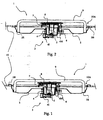
Fig. 1 and Fig. 2 show, in a cross section view with respect to a transversal plane, a cooking element according to the present invention in two of its possible realisations; -
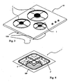
Figure 3 shows an assembled cooking hob according to the present invention; -
Figure 4 shows an escalation view of a possible variant of a cooking element according to this invention. - In the figures listed above a cooking element, and more specifically, a gas burner, referenced 1, while a cooking hob including said elements referenced 10. Said
cooking hob 10 presentshousing holes 10A for saidcooking elements 1. - In particular, a
cooking element 1 or a gas burner made up of acover 2 with a threaded hole in the centre is illustrated inFig. 1 and Fig. 2 . A cup 4 of a burner element is screwed into said hole, and referenced 3. - As known, the cup 4 presents a
mouth 41 apt to be connected to a gas hose that passes below thecooking hob 10, terminating with a threaded outlet onto which anozzle 5 is screwed to distribute a settled quantity of gas. As known, saidnozzle 5 is regulated to supply a certain heat capacity togas burner 1. - The cup 4 shows then a
small shelf 4M on the side drilled with a hole for the insertion of known auxiliary means such as anignition plug 6 to strike the flame in the gas burner and/or a thermocouple to activate a safety protection system against gas leaks, this not being illustrated for simplicity's sake. - A flame separator element 7 closed on top by a
cap 8 is positioned above the cup support 4. As known, the gas to be burnt, coming from an external duct fastened to themouth 41, spreads inside the cup 4 of thegas burner element 3 mixing with the air; finally, the gas bums coming out through the flame separator element 7. -
Cover 2 of thegas burner 1 showsseats 2S near the bottom of saidcover 2, into which the arms of a pot-holder 9 are lodged. The conformation of theexternal edge 2B of thecover 2 is a particularly important component ofcooking element 1. InFig. 1 saidexternal edge 2B is folded over slightly in a downward direction to provide greater stability in supportingcover 2, and consequently thewhole cooking element 1. - Conveniently, the
cooking hob 10 could have a flared form near thehousing hole 10A of thecooking element 1, in order to better employ theexternal edge 2B of thecooking element 1 stably supported. -
Fig. 2 shows theexternal edge 2B in a flat version apt to be attached in a common way to the lower surface ofcooking hob 10. For example, fixing elements such as screws could be used in order to be applied from the bottom to the top, rivets, or even plain pasting with suitable heat resistant glues. Said fixing elements, not illustrated for simplicity's sake, could further constitute stylized and visible elements to contribute to a new and original appearance of thewhole cooking hob 10. -
Fig. 3 shows acooking hob 10 according to the invention that seems to be completely similar to the cooking hobs currently on the market. In particular, saidcooking hob 10 shows threecooking elements 1 made up of gas burners with various capacities inserted into threehousing holes 10A of compatible sizes. The employedcooking elements 1 are of the type shown inFig. 1 as can be seen by theraised edges 2B having light-coloured lines inFig. 3 , that abut on the edge of thehousing holes 10A. - According to this innovative modularity of
cooking elements 1, it is possible to form thecooking hob 10 according to the widest range of geometrical and architectural layouts possible, in a manner that is compatible with design needs of capacity and weight that the openings in thehob 10 must satisfy in order to lodge eachcooking element 1. - In fact, to this aim it is necessary to prepare only a single cooking hob mould, having compatible sizes with those of the furniture opening where it will be inserted. This will satisfy every possible variant and layout, since said hobs are later cut and/or tool machined to drill the holes where the cooking elements will be inserted basically flush with the cooking hob surface.
- Therefore it is obvious that a new cooking hob of the same sizes will only require different tool machining after the moulding stage, and not a new and different mould as requested in the present state of the art. The creativity of designers and technicians is inspired to a greater extent by this new type of cooking hobs that permits the realisation of different variants of the same cooking hob at low cost.
- A different illustration of the cooking element, i.e. the gas burner illustrated in
Fig. 1 , is shown inFig. 4 , and referenced 1'. This burner 1' presents a burner element 3' of the so-called "square" type, widely illustrated and described in the Patent for an Italian utility model N°TO2002U000101 Fig. 4 shows the particular square shape of the cover 2', having aflat edge 2B' preferably apt to be connected to acooking hob 10 on the respective lower surface, aligned withhousing hole 10A. - The features of the cooking hobs including cooking elements of particular constitution, according to this invention, are made apparent by the description and the annexed drawings, just as the advantages to be gained.
- Said cooking hobs can be fitted to the widest range of design requirements and different layouts of the elements in a versatile, economical and efficient manner. Moreover, it is possible to combine gas burners with different applied heat capacities, as well as gas burners with cooking elements of other types such as electric, radiant hot plates, grills etc.
- The most important aspect therefore, is the possibility of realising cooking hobs with different types and variants in a simple and easy manner without having to fit whole production lines or produce new moulds for this purpose with all the relative costs involved.
- One advantage is therefore to be able to obtain considerable productive flexibility of said cooking hobs using a new realization modularity, reduced costs, and wide possibilities of personalized design for cooking hob layout.
- It is obvious that many changes are possible for the man skilled in the art, to cooking hobs including cooking elements of particular constitution described as an example, without departing from the novelty principles of the inventive idea, as it is also obvious that in the practical construction, the forms of the illustrated details can be different and the latter replaced by other elements that are technically equivalent.
- One variant that should be strongly underlined is the use, during the setting up of a cooking hob according to the present invention, of any type of a cooking elements currently known in the state of the art. For example, the gas burners shown in
Fig. 1-4 can be combined with or replaced by electric or radiant hot plates, grill or barbecue type elements, either electrically controlled, or charcoal burners.
Claims (6)
- Built-in type cooking hob, particularly apt to be easily and conveniently mounted in a single unit in suitable openings of kitchen furniture, comprising at least one cooking element (1) of a type apt to be assembled with the cooking hob (10) in housing holes (10A) present in said cooking hob (10), in order to realise functional and stylistic changes to the cooking hob (10) in a simple and economical manner, said cooking element (1) being made for being modular and able to be inserted in a predetermined hole (10A) of said cooking hob (10) and providing first means which comprise a cover (2) fitted to close the external surface of said cooking hob (10), as a support for second means (3) to generate cooking heat and to contain any possible liquids or wastes that commonly drop onto a cooking hob (10), said cover (2) comprising an external edge (2B) that allows the coupling of said cover (2) with the cooking hob (10),
wherein,
in order to realise efficient and complete modularity of said cooking element (1), said cover (2) comprises:- third means for the stable attachment of said second means (3) to said cover (2);- seats (2S) near the bottom of said cover (2) onto which the arms of a pot-holder (9) abutting lodge,wherein said external edge (2B) is flat and suited for the stable attachment, through fixing means, of said cover (2) to the lower surface of said cooking hob (10) aligned with said housing hole (10A), or wherein said external edge (2B) is folded over slightly in a downwards direction and is apt to act as a stable support as said cooking hob (10). - Cooking hob, according to the previous claim, characterized in that said second means (3) comprise a plurality of detachable elements (4, 7, 8) in order to improve the modularity of said cooking element (1).
- Cooking hob, according to the previous claim, characterized in that said cooking element (1) comprises a gas burner, and therefore said second means of said cooking element (1) comprise a burner element (3) of said gas burner (1).
- Cooking hob, according to claim 2, characterized in that said plurality of detachable elements (4, 7, 8) comprise a flame separator element (7) closed on the top by a cap (8) positioned above a cup support (4).
- Cooking hob, according to the previous claim, characterized in that said third means of said cover (2) of said cooking element (1) comprise a threaded hole to internally house said second means (3) through a screwing action.
- Cooking hob, according to one or more of the previous Claims characterized in that said cooking elements connected to said cooking hob (10) are gas burners (1; 1') and/or electric or radiant hot plates, and/or grill or barbecue type grills, either electrically controlled or charcoal burners.
Priority Applications (2)
| Application Number | Priority Date | Filing Date | Title |
|---|---|---|---|
| SI200330830T SI1520136T1 (en) | 2002-07-01 | 2003-06-24 | Cooking hobs including cooking elements of particular constitution |
| DE60312522.0T DE60312522T3 (en) | 2002-07-01 | 2003-06-24 | Hobs with a special shape |
Applications Claiming Priority (3)
| Application Number | Priority Date | Filing Date | Title |
|---|---|---|---|
| ITTO20020128U | 2002-07-01 | ||
| IT2002TO000128U ITTO20020128U1 (en) | 2002-07-01 | 2002-07-01 | COOKING PLATES INCLUDING COOKING ELEMENTS OF PARTICULAR CONSTITUTION. |
| PCT/IB2003/002445 WO2004003435A1 (en) | 2002-07-01 | 2003-06-24 | Cooking hobs including cooking elements of particular constitution |
Publications (3)
| Publication Number | Publication Date |
|---|---|
| EP1520136A1 EP1520136A1 (en) | 2005-04-06 |
| EP1520136B1 EP1520136B1 (en) | 2007-03-14 |
| EP1520136B2 true EP1520136B2 (en) | 2015-07-08 |
Family
ID=27621207
Family Applications (1)
| Application Number | Title | Priority Date | Filing Date |
|---|---|---|---|
| EP03732824.2A Expired - Lifetime EP1520136B2 (en) | 2002-07-01 | 2003-06-24 | Cooking hobs including cooking elements of particular constitution |
Country Status (11)
| Country | Link |
|---|---|
| EP (1) | EP1520136B2 (en) |
| AT (1) | ATE356959T1 (en) |
| AU (1) | AU2003240209A1 (en) |
| DE (1) | DE60312522T3 (en) |
| DK (1) | DK1520136T3 (en) |
| ES (1) | ES2282635T3 (en) |
| IT (1) | ITTO20020128U1 (en) |
| PT (1) | PT1520136E (en) |
| RU (1) | RU2320927C2 (en) |
| SI (1) | SI1520136T1 (en) |
| WO (1) | WO2004003435A1 (en) |
Families Citing this family (2)
| Publication number | Priority date | Publication date | Assignee | Title |
|---|---|---|---|---|
| CA2718563A1 (en) | 2008-04-04 | 2009-10-08 | Aktiebolaget Electrolux (Publ) | A trivet |
| TR201712901A1 (en) * | 2017-08-28 | 2019-03-21 | Arcelik As | A COOKER WITH A BURNER'S HOLE |
Family Cites Families (7)
| Publication number | Priority date | Publication date | Assignee | Title |
|---|---|---|---|---|
| US2232482A (en) * | 1938-04-30 | 1941-02-18 | G & J Teller | Cooking range |
| US3625196A (en) * | 1970-05-05 | 1971-12-07 | W J Schoenberger Co The | Burner cap assembly |
| US3830216A (en) * | 1971-03-15 | 1974-08-20 | Owens Illinois Inc | Countertop heating apparatus |
| US3877865A (en) * | 1972-11-16 | 1975-04-15 | Lincoln Brass Works | Gas burner and aeration pan assembly |
| SU619759A1 (en) * | 1973-06-05 | 1978-08-15 | Головное Специальное Конструкторско-Технологическое Бюро "Газоаппарат" | Gas stove |
| GB2068104A (en) * | 1980-01-21 | 1981-08-05 | Kirby James N Pty Ltd | Cooking tops |
| RU2037744C1 (en) * | 1992-10-08 | 1995-06-19 | Государственное научно-производственное предприятие "Сплав" | Gas single-burner table stove |
-
2002
- 2002-07-01 IT IT2002TO000128U patent/ITTO20020128U1/en unknown
-
2003
- 2003-06-24 DK DK03732824T patent/DK1520136T3/en active
- 2003-06-24 EP EP03732824.2A patent/EP1520136B2/en not_active Expired - Lifetime
- 2003-06-24 AT AT03732824T patent/ATE356959T1/en not_active IP Right Cessation
- 2003-06-24 RU RU2005102403/03A patent/RU2320927C2/en not_active IP Right Cessation
- 2003-06-24 AU AU2003240209A patent/AU2003240209A1/en not_active Abandoned
- 2003-06-24 SI SI200330830T patent/SI1520136T1/en unknown
- 2003-06-24 PT PT03732824T patent/PT1520136E/en unknown
- 2003-06-24 WO PCT/IB2003/002445 patent/WO2004003435A1/en not_active Ceased
- 2003-06-24 ES ES03732824T patent/ES2282635T3/en not_active Expired - Lifetime
- 2003-06-24 DE DE60312522.0T patent/DE60312522T3/en not_active Expired - Lifetime
Also Published As
| Publication number | Publication date |
|---|---|
| DK1520136T3 (en) | 2007-07-02 |
| WO2004003435A1 (en) | 2004-01-08 |
| SI1520136T1 (en) | 2007-08-31 |
| DE60312522T2 (en) | 2007-11-29 |
| RU2320927C2 (en) | 2008-03-27 |
| DE60312522T3 (en) | 2015-10-08 |
| EP1520136A1 (en) | 2005-04-06 |
| ITTO20020128V0 (en) | 2002-07-01 |
| EP1520136B1 (en) | 2007-03-14 |
| RU2005102403A (en) | 2005-07-10 |
| ITTO20020128U1 (en) | 2004-01-02 |
| PT1520136E (en) | 2007-05-31 |
| AU2003240209A1 (en) | 2004-01-19 |
| ES2282635T3 (en) | 2007-10-16 |
| DE60312522D1 (en) | 2007-04-26 |
| ATE356959T1 (en) | 2007-04-15 |
Similar Documents
| Publication | Publication Date | Title |
|---|---|---|
| US10281157B2 (en) | Gas cooktop with integrated wok | |
| US6598598B1 (en) | Charcoal grill with cool base | |
| CN203852233U (en) | Circular combined stove with barbecue grill and electric griddle | |
| US9423138B2 (en) | Gas cooktop with radiant burner arrangement | |
| EP1520136B2 (en) | Cooking hobs including cooking elements of particular constitution | |
| KR102073380B1 (en) | Mult ignition tools for portable gas burner | |
| CN206160222U (en) | Dual -purpose modularization concatenation cooking utensils of gas electricity | |
| CA2691387C (en) | Pedestal for a burner of a household appliance | |
| CA2446847A1 (en) | Gas grate locating assembly for a ceramic-based cooktop | |
| CN218626832U (en) | Atmospheric infrared mixed stove burner | |
| CN107536259B (en) | A kind of integrated intelligent safely hides Multifunction cold-warm table | |
| CN215489871U (en) | Embedded kitchen cabinet and kitchen range combustion system thereof | |
| CN216431713U (en) | Go up air inlet furnace end and combustor that has this furnace end | |
| CN210241654U (en) | Upper air inlet gas stove | |
| CN111720823A (en) | Burner fire cover | |
| CN214468606U (en) | Combustor and gas stove | |
| CN215456503U (en) | Embedded stove cabinet | |
| CN215523411U (en) | Cooking utensils | |
| CN215336563U (en) | Smoke and stove integrated machine | |
| CN210485711U (en) | Full upper air inlet type stove burner | |
| CN213808208U (en) | Air guide assembly and cooking utensil with same | |
| KR200427460Y1 (en) | Portable Gas Stove | |
| JP3151181B2 (en) | pot | |
| CN113654086A (en) | Embedded kitchen cabinet and kitchen range combustion system thereof | |
| HK1236603B (en) | Gas cooktop with integrated wok |
Legal Events
| Date | Code | Title | Description |
|---|---|---|---|
| PUAI | Public reference made under article 153(3) epc to a published international application that has entered the european phase |
Free format text: ORIGINAL CODE: 0009012 |
|
| 17P | Request for examination filed |
Effective date: 20050127 |
|
| AK | Designated contracting states |
Kind code of ref document: A1 Designated state(s): AT BE BG CH CY CZ DE DK EE ES FI FR GB GR HU IE IT LI LU MC NL PT RO SE SI SK TR |
|
| AX | Request for extension of the european patent |
Extension state: AL LT LV MK |
|
| DAX | Request for extension of the european patent (deleted) | ||
| GRAP | Despatch of communication of intention to grant a patent |
Free format text: ORIGINAL CODE: EPIDOSNIGR1 |
|
| GRAS | Grant fee paid |
Free format text: ORIGINAL CODE: EPIDOSNIGR3 |
|
| GRAA | (expected) grant |
Free format text: ORIGINAL CODE: 0009210 |
|
| AK | Designated contracting states |
Kind code of ref document: B1 Designated state(s): AT BE BG CH CY CZ DE DK EE ES FI FR GB GR HU IE IT LI LU MC NL PT RO SE SI SK TR |
|
| PG25 | Lapsed in a contracting state [announced via postgrant information from national office to epo] |
Ref country code: CH Free format text: LAPSE BECAUSE OF FAILURE TO SUBMIT A TRANSLATION OF THE DESCRIPTION OR TO PAY THE FEE WITHIN THE PRESCRIBED TIME-LIMIT Effective date: 20070314 Ref country code: AT Free format text: LAPSE BECAUSE OF FAILURE TO SUBMIT A TRANSLATION OF THE DESCRIPTION OR TO PAY THE FEE WITHIN THE PRESCRIBED TIME-LIMIT Effective date: 20070314 Ref country code: LI Free format text: LAPSE BECAUSE OF FAILURE TO SUBMIT A TRANSLATION OF THE DESCRIPTION OR TO PAY THE FEE WITHIN THE PRESCRIBED TIME-LIMIT Effective date: 20070314 |
|
| REG | Reference to a national code |
Ref country code: GB Ref legal event code: FG4D |
|
| REG | Reference to a national code |
Ref country code: RO Ref legal event code: EPE |
|
| REG | Reference to a national code |
Ref country code: CH Ref legal event code: EP |
|
| REF | Corresponds to: |
Ref document number: 60312522 Country of ref document: DE Date of ref document: 20070426 Kind code of ref document: P |
|
| REG | Reference to a national code |
Ref country code: IE Ref legal event code: FG4D |
|
| REG | Reference to a national code |
Ref country code: SE Ref legal event code: TRGR |
|
| REG | Reference to a national code |
Ref country code: PT Ref legal event code: SC4A Free format text: AVAILABILITY OF NATIONAL TRANSLATION Effective date: 20070511 |
|
| REG | Reference to a national code |
Ref country code: EE Ref legal event code: FG4A Ref document number: E001122 Country of ref document: EE Effective date: 20070423 |
|
| REG | Reference to a national code |
Ref country code: DK Ref legal event code: T3 |
|
| REG | Reference to a national code |
Ref country code: HU Ref legal event code: AG4A Ref document number: E001632 Country of ref document: HU |
|
| ET | Fr: translation filed | ||
| REG | Reference to a national code |
Ref country code: CH Ref legal event code: PL |
|
| REG | Reference to a national code |
Ref country code: ES Ref legal event code: FG2A Ref document number: 2282635 Country of ref document: ES Kind code of ref document: T3 |
|
| PLBI | Opposition filed |
Free format text: ORIGINAL CODE: 0009260 |
|
| 26 | Opposition filed |
Opponent name: AEG HAUSGERAETE GMBH Effective date: 20071203 |
|
| PLAX | Notice of opposition and request to file observation + time limit sent |
Free format text: ORIGINAL CODE: EPIDOSNOBS2 |
|
| PG25 | Lapsed in a contracting state [announced via postgrant information from national office to epo] |
Ref country code: MC Free format text: LAPSE BECAUSE OF NON-PAYMENT OF DUE FEES Effective date: 20070630 |
|
| NLR1 | Nl: opposition has been filed with the epo |
Opponent name: AEG HAUSGERAETE GMBH |
|
| PG25 | Lapsed in a contracting state [announced via postgrant information from national office to epo] |
Ref country code: GR Free format text: LAPSE BECAUSE OF FAILURE TO SUBMIT A TRANSLATION OF THE DESCRIPTION OR TO PAY THE FEE WITHIN THE PRESCRIBED TIME-LIMIT Effective date: 20070615 |
|
| PLBB | Reply of patent proprietor to notice(s) of opposition received |
Free format text: ORIGINAL CODE: EPIDOSNOBS3 |
|
| PGFP | Annual fee paid to national office [announced via postgrant information from national office to epo] |
Ref country code: CZ Payment date: 20080512 Year of fee payment: 8 Ref country code: DK Payment date: 20080627 Year of fee payment: 6 Ref country code: HU Payment date: 20080613 Year of fee payment: 6 |
|
| PGFP | Annual fee paid to national office [announced via postgrant information from national office to epo] |
Ref country code: RO Payment date: 20080602 Year of fee payment: 6 Ref country code: SK Payment date: 20080519 Year of fee payment: 6 |
|
| PGFP | Annual fee paid to national office [announced via postgrant information from national office to epo] |
Ref country code: PT Payment date: 20080521 Year of fee payment: 6 Ref country code: SI Payment date: 20080526 Year of fee payment: 6 Ref country code: FI Payment date: 20080625 Year of fee payment: 6 Ref country code: BG Payment date: 20080626 Year of fee payment: 6 Ref country code: EE Payment date: 20080520 Year of fee payment: 6 |
|
| PGFP | Annual fee paid to national office [announced via postgrant information from national office to epo] |
Ref country code: IE Payment date: 20080622 Year of fee payment: 6 Ref country code: NL Payment date: 20080630 Year of fee payment: 6 Ref country code: SE Payment date: 20080626 Year of fee payment: 6 |
|
| PGFP | Annual fee paid to national office [announced via postgrant information from national office to epo] |
Ref country code: BE Payment date: 20080701 Year of fee payment: 6 |
|
| PG25 | Lapsed in a contracting state [announced via postgrant information from national office to epo] |
Ref country code: CY Free format text: LAPSE BECAUSE OF FAILURE TO SUBMIT A TRANSLATION OF THE DESCRIPTION OR TO PAY THE FEE WITHIN THE PRESCRIBED TIME-LIMIT Effective date: 20070314 |
|
| PGFP | Annual fee paid to national office [announced via postgrant information from national office to epo] |
Ref country code: ES Payment date: 20090622 Year of fee payment: 7 |
|
| PG25 | Lapsed in a contracting state [announced via postgrant information from national office to epo] |
Ref country code: LU Free format text: LAPSE BECAUSE OF NON-PAYMENT OF DUE FEES Effective date: 20070624 |
|
| PG25 | Lapsed in a contracting state [announced via postgrant information from national office to epo] |
Ref country code: TR Free format text: LAPSE BECAUSE OF FAILURE TO SUBMIT A TRANSLATION OF THE DESCRIPTION OR TO PAY THE FEE WITHIN THE PRESCRIBED TIME-LIMIT Effective date: 20070314 |
|
| PLAB | Opposition data, opponent's data or that of the opponent's representative modified |
Free format text: ORIGINAL CODE: 0009299OPPO |
|
| BERE | Be: lapsed |
Owner name: INDESIT COMPANY S.P.A. Effective date: 20090630 |
|
| REG | Reference to a national code |
Ref country code: PT Ref legal event code: MM4A Free format text: LAPSE DUE TO NON-PAYMENT OF FEES Effective date: 20091228 |
|
| PG25 | Lapsed in a contracting state [announced via postgrant information from national office to epo] |
Ref country code: FI Free format text: LAPSE BECAUSE OF NON-PAYMENT OF DUE FEES Effective date: 20090624 |
|
| REG | Reference to a national code |
Ref country code: DK Ref legal event code: EBP |
|
| REG | Reference to a national code |
Ref country code: EE Ref legal event code: MM4A Ref document number: E001122 Country of ref document: EE Effective date: 20090630 |
|
| NLV4 | Nl: lapsed or anulled due to non-payment of the annual fee |
Effective date: 20100101 |
|
| REG | Reference to a national code |
Ref country code: SK Ref legal event code: MM4A Ref document number: E 1988 Country of ref document: SK Effective date: 20090624 |
|
| PG25 | Lapsed in a contracting state [announced via postgrant information from national office to epo] |
Ref country code: PT Free format text: LAPSE BECAUSE OF NON-PAYMENT OF DUE FEES Effective date: 20091228 |
|
| REG | Reference to a national code |
Ref country code: SI Ref legal event code: KO00 Effective date: 20100205 |
|
| PG25 | Lapsed in a contracting state [announced via postgrant information from national office to epo] |
Ref country code: IE Free format text: LAPSE BECAUSE OF NON-PAYMENT OF DUE FEES Effective date: 20090624 Ref country code: EE Free format text: LAPSE BECAUSE OF NON-PAYMENT OF DUE FEES Effective date: 20090630 Ref country code: HU Free format text: LAPSE BECAUSE OF NON-PAYMENT OF DUE FEES Effective date: 20090625 Ref country code: RO Free format text: LAPSE BECAUSE OF NON-PAYMENT OF DUE FEES Effective date: 20090624 |
|
| PG25 | Lapsed in a contracting state [announced via postgrant information from national office to epo] |
Ref country code: SK Free format text: LAPSE BECAUSE OF NON-PAYMENT OF DUE FEES Effective date: 20090624 Ref country code: SI Free format text: LAPSE BECAUSE OF NON-PAYMENT OF DUE FEES Effective date: 20090625 |
|
| PG25 | Lapsed in a contracting state [announced via postgrant information from national office to epo] |
Ref country code: BE Free format text: LAPSE BECAUSE OF NON-PAYMENT OF DUE FEES Effective date: 20090630 |
|
| PG25 | Lapsed in a contracting state [announced via postgrant information from national office to epo] |
Ref country code: NL Free format text: LAPSE BECAUSE OF NON-PAYMENT OF DUE FEES Effective date: 20100101 Ref country code: DK Free format text: LAPSE BECAUSE OF NON-PAYMENT OF DUE FEES Effective date: 20090630 |
|
| PG25 | Lapsed in a contracting state [announced via postgrant information from national office to epo] |
Ref country code: BG Free format text: LAPSE BECAUSE OF FAILURE TO SUBMIT A TRANSLATION OF THE DESCRIPTION OR TO PAY THE FEE WITHIN THE PRESCRIBED TIME-LIMIT Effective date: 20090630 |
|
| PG25 | Lapsed in a contracting state [announced via postgrant information from national office to epo] |
Ref country code: SE Free format text: LAPSE BECAUSE OF NON-PAYMENT OF DUE FEES Effective date: 20090625 |
|
| REG | Reference to a national code |
Ref country code: ES Ref legal event code: FD2A Effective date: 20110715 |
|
| PG25 | Lapsed in a contracting state [announced via postgrant information from national office to epo] |
Ref country code: ES Free format text: LAPSE BECAUSE OF NON-PAYMENT OF DUE FEES Effective date: 20110705 |
|
| PG25 | Lapsed in a contracting state [announced via postgrant information from national office to epo] |
Ref country code: ES Free format text: LAPSE BECAUSE OF NON-PAYMENT OF DUE FEES Effective date: 20100625 |
|
| PG25 | Lapsed in a contracting state [announced via postgrant information from national office to epo] |
Ref country code: CZ Free format text: LAPSE BECAUSE OF NON-PAYMENT OF DUE FEES Effective date: 20110624 |
|
| PLAB | Opposition data, opponent's data or that of the opponent's representative modified |
Free format text: ORIGINAL CODE: 0009299OPPO |
|
| R26 | Opposition filed (corrected) |
Opponent name: ELECTROLUX ROTHENBURG GMBH FACTORY AND DEVELOPMENT Effective date: 20071203 |
|
| APAH | Appeal reference modified |
Free format text: ORIGINAL CODE: EPIDOSCREFNO |
|
| APBM | Appeal reference recorded |
Free format text: ORIGINAL CODE: EPIDOSNREFNO |
|
| APBP | Date of receipt of notice of appeal recorded |
Free format text: ORIGINAL CODE: EPIDOSNNOA2O |
|
| APBQ | Date of receipt of statement of grounds of appeal recorded |
Free format text: ORIGINAL CODE: EPIDOSNNOA3O |
|
| APBU | Appeal procedure closed |
Free format text: ORIGINAL CODE: EPIDOSNNOA9O |
|
| PUAH | Patent maintained in amended form |
Free format text: ORIGINAL CODE: 0009272 |
|
| STAA | Information on the status of an ep patent application or granted ep patent |
Free format text: STATUS: PATENT MAINTAINED AS AMENDED |
|
| 27A | Patent maintained in amended form |
Effective date: 20150708 |
|
| AK | Designated contracting states |
Kind code of ref document: B2 Designated state(s): AT BE BG CH CY CZ DE DK EE ES FI FR GB GR HU IE IT LI LU MC NL PT RO SE SI SK TR |
|
| REG | Reference to a national code |
Ref country code: DE Ref legal event code: R102 Ref document number: 60312522 Country of ref document: DE |
|
| REG | Reference to a national code |
Ref country code: FR Ref legal event code: PLFP Year of fee payment: 14 |
|
| REG | Reference to a national code |
Ref country code: FR Ref legal event code: PLFP Year of fee payment: 15 |
|
| PGFP | Annual fee paid to national office [announced via postgrant information from national office to epo] |
Ref country code: FR Payment date: 20170511 Year of fee payment: 15 Ref country code: GB Payment date: 20170621 Year of fee payment: 15 |
|
| PGFP | Annual fee paid to national office [announced via postgrant information from national office to epo] |
Ref country code: IT Payment date: 20170619 Year of fee payment: 15 |
|
| PGFP | Annual fee paid to national office [announced via postgrant information from national office to epo] |
Ref country code: DE Payment date: 20170621 Year of fee payment: 15 |
|
| REG | Reference to a national code |
Ref country code: DE Ref legal event code: R119 Ref document number: 60312522 Country of ref document: DE |
|
| PG25 | Lapsed in a contracting state [announced via postgrant information from national office to epo] |
Ref country code: BG Free format text: LAPSE BECAUSE OF FAILURE TO SUBMIT A TRANSLATION OF THE DESCRIPTION OR TO PAY THE FEE WITHIN THE PRESCRIBED TIME-LIMIT Effective date: 20170808 |
|
| GBPC | Gb: european patent ceased through non-payment of renewal fee |
Effective date: 20180624 |
|
| PG25 | Lapsed in a contracting state [announced via postgrant information from national office to epo] |
Ref country code: FR Free format text: LAPSE BECAUSE OF NON-PAYMENT OF DUE FEES Effective date: 20180630 Ref country code: IT Free format text: LAPSE BECAUSE OF NON-PAYMENT OF DUE FEES Effective date: 20180624 Ref country code: GB Free format text: LAPSE BECAUSE OF NON-PAYMENT OF DUE FEES Effective date: 20180624 Ref country code: DE Free format text: LAPSE BECAUSE OF NON-PAYMENT OF DUE FEES Effective date: 20190101 |