EP1519486A2 - Hörhilfegerät mit magnetfeldgesteuertem Schalter und entsprechendes Verfahren zum Betreiben eines Hörhilfegeräts - Google Patents
Hörhilfegerät mit magnetfeldgesteuertem Schalter und entsprechendes Verfahren zum Betreiben eines Hörhilfegeräts Download PDFInfo
- Publication number
- EP1519486A2 EP1519486A2 EP04021820A EP04021820A EP1519486A2 EP 1519486 A2 EP1519486 A2 EP 1519486A2 EP 04021820 A EP04021820 A EP 04021820A EP 04021820 A EP04021820 A EP 04021820A EP 1519486 A2 EP1519486 A2 EP 1519486A2
- Authority
- EP
- European Patent Office
- Prior art keywords
- hearing aid
- magnetic field
- ferrite
- switching device
- function
- Prior art date
- Legal status (The legal status is an assumption and is not a legal conclusion. Google has not performed a legal analysis and makes no representation as to the accuracy of the status listed.)
- Withdrawn
Links
Images
Classifications
-
- H—ELECTRICITY
- H04—ELECTRIC COMMUNICATION TECHNIQUE
- H04R—LOUDSPEAKERS, MICROPHONES, GRAMOPHONE PICK-UPS OR LIKE ACOUSTIC ELECTROMECHANICAL TRANSDUCERS; ELECTRIC HEARING AIDS; PUBLIC ADDRESS SYSTEMS
- H04R25/00—Electric hearing aids
- H04R25/55—Electric hearing aids using an external connection, either wireless or wired
- H04R25/554—Electric hearing aids using an external connection, either wireless or wired using a wireless connection, e.g. between microphone and amplifier or using Tcoils
-
- H—ELECTRICITY
- H04—ELECTRIC COMMUNICATION TECHNIQUE
- H04R—LOUDSPEAKERS, MICROPHONES, GRAMOPHONE PICK-UPS OR LIKE ACOUSTIC ELECTROMECHANICAL TRANSDUCERS; ELECTRIC HEARING AIDS; PUBLIC ADDRESS SYSTEMS
- H04R25/00—Electric hearing aids
- H04R25/43—Electronic input selection or mixing based on input signal analysis, e.g. mixing or selection between microphone and telecoil or between microphones with different directivity characteristics
-
- H—ELECTRICITY
- H04—ELECTRIC COMMUNICATION TECHNIQUE
- H04R—LOUDSPEAKERS, MICROPHONES, GRAMOPHONE PICK-UPS OR LIKE ACOUSTIC ELECTROMECHANICAL TRANSDUCERS; ELECTRIC HEARING AIDS; PUBLIC ADDRESS SYSTEMS
- H04R2225/00—Details of deaf aids covered by H04R25/00, not provided for in any of its subgroups
- H04R2225/61—Aspects relating to mechanical or electronic switches or control elements, e.g. functioning
-
- H—ELECTRICITY
- H04—ELECTRIC COMMUNICATION TECHNIQUE
- H04R—LOUDSPEAKERS, MICROPHONES, GRAMOPHONE PICK-UPS OR LIKE ACOUSTIC ELECTROMECHANICAL TRANSDUCERS; ELECTRIC HEARING AIDS; PUBLIC ADDRESS SYSTEMS
- H04R25/00—Electric hearing aids
- H04R25/60—Mounting or interconnection of hearing aid parts, e.g. inside tips, housings or to ossicles
- H04R25/603—Mounting or interconnection of hearing aid parts, e.g. inside tips, housings or to ossicles of mechanical or electronic switches or control elements
Definitions
- the present invention relates to a hearing aid with a first hearing aid function, a second hearing aid function and a switching device for automatically switching the first hearing aid function in the second hearing aid function. Moreover, the present invention relates to a corresponding Method for operating a hearing aid.
- Another application for magnetic-field-controlled, automatic Turning on a hearing aid is its automatic Shut down when the device is in the storage box or Charging station is placed.
- Magnet in the storage box or charging station and switches through its magnetic DC field the reed contact in the hearing aid, so that this without pressing a control component is turned off.
- a disadvantage of the reed contacts are their volume and their movable contact elements, the on the one hand require a high production cost and the others have a correspondingly low life.
- the object of the present invention is therefore to To provide a hearing aid, with reduced manufacturing costs and increased compactness and durability is automatically switchable.
- this object is achieved by a hearing aid with a first hearing aid function, a second hearing aid function and a switching device for automatic Switching from the first hearing aid function to the second hearing aid function, wherein the switching device at least one magnetic field-controlled ferrite component, whose impedance change as a basis for automatic switching is usable.
- the invention is based on the idea that for the automatic Turn a hearing aid the change of permeability a ferrite component depending on an applied Magnetic field can be exploited.
- the continuous Permeability change as a function of the strength of the applied magnetic field causes an impedance or inductance change a suitable ferrite component and can be used to trigger a switching operation.
- the first hearing aid function comprises a microphone operation and the second hearing aid function a telecoil operation.
- This can automatically when calling from the microphone mode be switched into the telecoil mode, if a telephone handset with permanent magnet applied to the ear becomes.
- the first hearing aid function can also be switched on and the second hearing aid function the off state correspond to the hearing aid.
- the hearing aid as mentioned above, for example by Insert into the storage box or charging station on and turned off.
- the magnetic field controlled ferrite component can by a SMD ferrite can be realized. Thus, this is usually in the High frequency range used device in the present Case used as a magnetic field sensor.
- the magnetic field controlled ferrite component can also be realized by a coil with ferrite core.
- the switching device preferably has an LC oscillator circuit, whose inductance is formed by the coil is to detect an inductance change of Coil with ferrite core.
- the switching device has via a bridge circuit for detecting the impedance change.
- the bridge circuit can be both frequency-dependent as well as frequency independent.
- a frequency-dependent bridge circuit for example two SMD ferrites can be used as bridge elements to to increase the sensitivity.
- the switching device is provided with a peak detector equipped with the maximum values of a AC signal, the impedance or inductance change is detectable. This can easily the Near a permanent magnet to the magnetic field controlled Component be determined in the hearing aid.
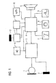
- the hearing aid shown in FIG 1 as a block diagram has two input components, namely a microphone 1 and a telecoil 2.
- the signals of both components are in a preamplifier 3 with A / D converter preamplified and digitized.
- the digital signal is in a signal processing 4 processed for a handset or speaker 5.
- a Battery 6 provides the necessary supply voltage for the Preamplifier 3 and the digital signal processing unit 4th
- the digital signal processing unit 4 is by means of a MTO switch in the microphone mode, the telecoil operation and the off state switchable.
- a programming jack 8 allows suitable programming of the digital signal processing unit 4.
- the digital signal processing circuit 4 may be correspondingly the environmental situation, for example, from the telecoil operation switched to a mixed operation with microphone become.
- the situation key 9 allows, for example the connection and disconnection of individual ones of several Microphones.
- a volume control 10 can finally in the usual way the volume of the hearing aid be set.
- a measuring bridge with evaluation circuit 11, to which an SMD ferrite sensor 12 is connected, is used to control the digital Signal processing device 4.
- the measuring bridge 11 and the digital signal processing device 4 are from a System clock unit 13, which essentially by an oscillator is formed, with a system clock or with a AC voltage supplied.
- a small SMD ferrite which is usually used in the high-frequency range, be used as a sensor for a static magnetic field.
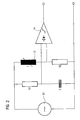
- FIG 2 The construction of the measuring bridge with evaluation circuit 11 is shown in FIG 2 shown in more detail.
- a Wheatstone bridge circuit is in a branch with the SMD ferrite 12 occupied. This one has under other inductive behavior with the letter "L" is marked.
- the remaining branches of the Wheatstone bridge circuit are in the usual way with ohmic elements R1 and R2 and occupied by a capacitive element C.
- the Wheatstone bridge circuit is powered by the system clock unit or the oscillator 13, which has a corresponding AC voltage is applied to the bridge. Because the circuit a represents frequency-independent AC bridge and thus independent of the oscillator frequency and harmonic content works, can be arbitrary and also frequency unstable Clock signals are used for bridge supply.
- the SMD ferrite is a static magnetic field flooded, changes through the existing magnetization the inductance of the component. As a result, the AC bridge becomes detuned and there is a correspondingly higher Voltage drop in the difference branch.
- the tapped in the differential branch of the measuring amplifier 14 AC voltage can with a in the measuring amplifier 14 integrated peak detector are evaluated. After subsequent Rectification and threshold analysis in the amplifier 14, one obtains a control signal for controlling the desired one Functions in the hearing aid or in the implant.
- a formed with a ferrite jacket surrounded electrical conductor can also be wound with a coil wire ferrite core be used as a magnetic field sensor. These too Ferrite coil can be evaluated by the AC bridge become.
- the AC bridge uses a LC oscillator circuit.
- the ferrite component acts as a frequency-determining element Component, i. it becomes the one associated with the impedance change Inductance change depending on the static Magnetic field used. In this case causes a magnetic Gleichfeld the detuning of the oscillator circuit.
- the frequency change is a measure of the strength of the existing magnetic field.
- a frequency-dependent bridge circuit can be used. This would have the advantage that two SMD ferrites or ferrite coils, which react to the magnetic field, are used can significantly increase the sensitivity. However, this requires a stable oscillator frequency.
- the magnetic field controlled Impedance represents.
- the Hall sensor has the Disadvantage of a relatively high electrical power consumption.
Landscapes
- Engineering & Computer Science (AREA)
- Physics & Mathematics (AREA)
- Health & Medical Sciences (AREA)
- General Health & Medical Sciences (AREA)
- Neurosurgery (AREA)
- Otolaryngology (AREA)
- Computer Networks & Wireless Communication (AREA)
- Acoustics & Sound (AREA)
- Signal Processing (AREA)
- Measuring Magnetic Variables (AREA)
- Coils Or Transformers For Communication (AREA)
- Telephone Function (AREA)
- Electronic Switches (AREA)
Abstract
Description
- der Magnetfeldsensor kann im Vergleich zu einem Miniatur-Reedkontakt (6mm x 1,5mm) sehr klein ausgestaltet sein, nämlich beispielsweise (2mm x 1mm)
- der Ferrit arbeitet verschleißfrei, denn er besitzt keine beweglichen Kontakte
- der Sensor kann verhältnismäßig günstig hergestellt werden
- ein Ferrit-Sensor arbeitet praktisch verzögerungsfrei
- die mit einer Ferrit-Sensorik notwendigen Zusatzbauteile können leicht mit in den Signalverarbeitungs-IC eines Hörhilfegeräts implementiert werden.
Claims (7)
- Hörhilfegerät miteiner ersten Hörhilfefunktion,einer zweiten Hörhilfefunktion undeiner Schalteinrichtung zum automatischen Schalten von der ersten Hörhilfefunktion in die zweite Hörhilfefunktion,
dadurch gekennzeichnet, dassdie Schalteinrichtung mindestens ein magnetfeldgesteuertes Ferrit-Bauelement(12) aufweist, dessen Impedanzänderung als Grundlage für das automatische Schalten verwendbar ist. - Hörhilfegerät nach Anspruch 1, wobei die erste Hörhilfefunktion einen Mikrofonbetrieb und die zweite Hörhilfefunktion einen Telefonspulenbetrieb umfasst.
- Hörhilfegerät nach Anspruch 1 oder 2, wobei das magnetfeldgesteuerte Ferrit-Bauelement (12) durch einen SMD-Ferrit realisiert ist.
- Hörhilfegerät nach Anspruch 1 oder 2, wobei das magnetfeldgesteuerte Ferrit-Bauelement (12) durch eine Spule mit Ferritkern realisiert ist.
- Hörhilfegerät nach einem der vorhergehenden Ansprüche, wobei die Schalteinrichtung über eine Brückenschaltung (11) zum Detektieren der Impedanzänderung verfügt.
- Hörhilfegerät nach Anspruch 4, wobei die Schalteinrichtung über eine LC-Oszillatorschaltung, deren Induktivität durch die Spule gebildet ist, zum Detektieren einer Induktivitätsänderung der Spule mit Ferritkern verfügt.
- Hörhilfegerät nach einem der vorhergehenden Ansprüche, wobei die Schalteinrichtung über einen Peakdetektor verfügt, so dass anhand der Höchstwerte eines Wechselspannungssignals die Impedanz- oder Induktivitätsänderung feststellb
Applications Claiming Priority (2)
| Application Number | Priority Date | Filing Date | Title |
|---|---|---|---|
| DE10344367 | 2003-09-24 | ||
| DE10344367A DE10344367B4 (de) | 2003-09-24 | 2003-09-24 | Hörhilfegerät mit magnetfeldgesteuertem Schalter und entsprechendes Verfahren zum Betreiben eines Hörhilfegeräts |
Publications (2)
| Publication Number | Publication Date |
|---|---|
| EP1519486A2 true EP1519486A2 (de) | 2005-03-30 |
| EP1519486A3 EP1519486A3 (de) | 2010-01-13 |
Family
ID=34177931
Family Applications (1)
| Application Number | Title | Priority Date | Filing Date |
|---|---|---|---|
| EP04021820A Withdrawn EP1519486A3 (de) | 2003-09-24 | 2004-09-14 | Hörhilfegerät mit magnetfeldgesteuertem Schalter und entsprechendes Verfahren zum Betreiben eines Hörhilfegeräts |
Country Status (4)
| Country | Link |
|---|---|
| US (1) | US7496206B2 (de) |
| EP (1) | EP1519486A3 (de) |
| AU (1) | AU2004214555B2 (de) |
| DE (1) | DE10344367B4 (de) |
Families Citing this family (11)
| Publication number | Priority date | Publication date | Assignee | Title |
|---|---|---|---|---|
| US20060210104A1 (en) * | 1998-10-28 | 2006-09-21 | Insound Medical, Inc. | Remote magnetic activation of hearing devices |
| US7016511B1 (en) * | 1998-10-28 | 2006-03-21 | Insound Medical, Inc. | Remote magnetic activation of hearing devices |
| AU2006303651B2 (en) * | 2005-10-17 | 2010-04-01 | Widex A/S | Hearing aid having selectable programmes, and method for changing the programme in a hearing aid |
| DE102006024713B3 (de) * | 2006-05-26 | 2007-08-30 | Siemens Audiologische Technik Gmbh | Hörvorrichtung mit einer Schwingkreisschaltung und entsprechendes Verfahren |
| DE102007039455A1 (de) * | 2007-08-21 | 2009-02-26 | Siemens Audiologische Technik Gmbh | Hörhilfegerätesystem mit Magnetfeldsensoren |
| DE102007039447A1 (de) * | 2007-08-21 | 2009-02-26 | Siemens Medical Instruments Pte. Ltd. | Verfahren zur Seitendefinition bei der Anpassung von Hörhilfen |
| DE102007054603B4 (de) * | 2007-11-15 | 2018-10-18 | Sivantos Pte. Ltd. | Hörvorrichtung mit gesteuerter Programmierbuchse |
| DK2071873T3 (en) * | 2007-12-11 | 2017-08-28 | Bernafon Ag | A hearing aid system comprising a custom filter and a measurement method |
| DE102012215976A1 (de) * | 2012-09-10 | 2014-03-13 | Siemens Medical Instruments Pte. Ltd. | Hörinstrument mit temperatursensitivem Bedienelement |
| SE537218C2 (sv) | 2013-08-07 | 2015-03-03 | Osseofon Ab | Elektrisk kopplingsanordning för implanterbar hörapparat |
| KR102506694B1 (ko) * | 2019-08-21 | 2023-03-07 | 주식회사 토닥 | 외장 마이크를 위한 인공 와우 외부기 |
Citations (5)
| Publication number | Priority date | Publication date | Assignee | Title |
|---|---|---|---|---|
| DE3109049C2 (de) | 1981-03-10 | 1989-06-08 | Siemens Ag, 1000 Berlin Und 8000 Muenchen, De | |
| DE3734946C2 (de) | 1987-10-15 | 1992-11-19 | Siemens Ag, 1000 Berlin Und 8000 Muenchen, De | |
| DE19633321A1 (de) | 1996-05-02 | 1997-11-06 | E A Olaf Greiner | Hörgerät und Betätigungselement für ein Hörgerät |
| DE29923019U1 (de) | 1999-12-30 | 2000-04-20 | auric Hörsysteme GmbH & Co. KG, 48429 Rheine | Anordnung zum Schalten eines Hörgerätes |
| EP1398995A2 (de) | 2002-09-16 | 2004-03-17 | Starkey Labs, Inc. | Schaltstruktur für Hörgerät |
Family Cites Families (1)
| Publication number | Priority date | Publication date | Assignee | Title |
|---|---|---|---|---|
| JPH0743442A (ja) * | 1993-07-30 | 1995-02-14 | Sony Corp | 地磁気方位センサー |
-
2003
- 2003-09-24 DE DE10344367A patent/DE10344367B4/de not_active Expired - Fee Related
-
2004
- 2004-09-14 EP EP04021820A patent/EP1519486A3/de not_active Withdrawn
- 2004-09-24 AU AU2004214555A patent/AU2004214555B2/en not_active Ceased
- 2004-09-24 US US10/949,893 patent/US7496206B2/en not_active Expired - Fee Related
Patent Citations (5)
| Publication number | Priority date | Publication date | Assignee | Title |
|---|---|---|---|---|
| DE3109049C2 (de) | 1981-03-10 | 1989-06-08 | Siemens Ag, 1000 Berlin Und 8000 Muenchen, De | |
| DE3734946C2 (de) | 1987-10-15 | 1992-11-19 | Siemens Ag, 1000 Berlin Und 8000 Muenchen, De | |
| DE19633321A1 (de) | 1996-05-02 | 1997-11-06 | E A Olaf Greiner | Hörgerät und Betätigungselement für ein Hörgerät |
| DE29923019U1 (de) | 1999-12-30 | 2000-04-20 | auric Hörsysteme GmbH & Co. KG, 48429 Rheine | Anordnung zum Schalten eines Hörgerätes |
| EP1398995A2 (de) | 2002-09-16 | 2004-03-17 | Starkey Labs, Inc. | Schaltstruktur für Hörgerät |
Also Published As
| Publication number | Publication date |
|---|---|
| EP1519486A3 (de) | 2010-01-13 |
| AU2004214555B2 (en) | 2008-10-23 |
| US7496206B2 (en) | 2009-02-24 |
| DE10344367A1 (de) | 2005-05-04 |
| AU2004214555A1 (en) | 2005-04-07 |
| DE10344367B4 (de) | 2010-01-14 |
| US20050105752A1 (en) | 2005-05-19 |
Similar Documents
| Publication | Publication Date | Title |
|---|---|---|
| EP0527719B1 (de) | Fernbedienungseinrichtung | |
| EP1519622B1 (de) | Hörhilfegerät mit automatischer Umschaltung der Spannungsversorgung für externe Komponenten und entsprechendes Verfahren | |
| DE102004019353B3 (de) | Hörhilfegerät mit einer Bedieneinrichtung | |
| DE3109049C2 (de) | ||
| DE102004023049B4 (de) | Hörgerätevorrichtung mit einer Schalteinrichtung zum An- und Abschalten sowie entsprechendes Verfahren | |
| DE4244968C2 (de) | Tragbares Funktelefon mit einem Antennenelement | |
| DE102007046437B4 (de) | Vollautomatisches Ein-/Ausschalten bei Hörhilfegeräten | |
| DE10344367B4 (de) | Hörhilfegerät mit magnetfeldgesteuertem Schalter und entsprechendes Verfahren zum Betreiben eines Hörhilfegeräts | |
| DE102007039455A1 (de) | Hörhilfegerätesystem mit Magnetfeldsensoren | |
| EP1623599B1 (de) | Mikrofonvorrichtung, XLR-Steckervorrichtung und drathlose Mikrofonempfangsvorrichtung | |
| EP2334102A2 (de) | Hörgerät mit einer platzsparenden Anordnung von Mikrofonen und Schallöffnungen | |
| EP1883274A1 (de) | Hörhilfe mit einem Radiofrequenzidentifikations-Empfänger zum Schalten einer Übertragungseigenschaft | |
| DE10145994A1 (de) | Steuerung eines Hörgeräts durch Klopfen | |
| DE10347212B3 (de) | Hörhilfevorrichtung zum automatischen Schalten in einen Telefonbetrieb und entsprechendes Verfahren | |
| EP1871140B1 (de) | Hörvorrichtung mit einer Schwingkreisschaltung und entsprechendes Verfahren | |
| DE102008054087A1 (de) | Hörhilfegerät mit mindestens einem kapazitiven Näherungssensor | |
| DE102007004814A1 (de) | Güteanpassung eines Empfangsschaltkreises | |
| EP3582512B1 (de) | Verfahren zur identifikation eines hörers, hörsystem und hörerset | |
| EP3836565A1 (de) | Leiterplatte eines hörgeräts | |
| DE102007054603B4 (de) | Hörvorrichtung mit gesteuerter Programmierbuchse | |
| DE102016200831A1 (de) | Hörgerät | |
| DE102023200779B3 (de) | Hörgerät | |
| EP1909535B1 (de) | Hörvorrichtung mit gesteuerten Eingangskanälen und entsprechendes Verfahren | |
| DE19809567C2 (de) | Hörgerät sowie Verfahren zur Unterdrückung magnetischer Störfelder | |
| EP3863304B1 (de) | Hörgerät mit induktiv gekoppelter antenneneinheit |
Legal Events
| Date | Code | Title | Description |
|---|---|---|---|
| PUAI | Public reference made under article 153(3) epc to a published international application that has entered the european phase |
Free format text: ORIGINAL CODE: 0009012 |
|
| AK | Designated contracting states |
Kind code of ref document: A2 Designated state(s): AT BE BG CH CY CZ DE DK EE ES FI FR GB GR HU IE IT LI LU MC NL PL PT RO SE SI SK TR |
|
| AX | Request for extension of the european patent |
Extension state: AL HR LT LV MK |
|
| PUAL | Search report despatched |
Free format text: ORIGINAL CODE: 0009013 |
|
| AK | Designated contracting states |
Kind code of ref document: A3 Designated state(s): AT BE BG CH CY CZ DE DK EE ES FI FR GB GR HU IE IT LI LU MC NL PL PT RO SE SI SK TR |
|
| AX | Request for extension of the european patent |
Extension state: AL HR LT LV MK |
|
| 17P | Request for examination filed |
Effective date: 20100607 |
|
| AKX | Designation fees paid |
Designated state(s): AT BE BG CH CY CZ DE DK EE ES FI FR GB GR HU IE IT LI LU MC NL PL PT RO SE SI SK TR |
|
| 17Q | First examination report despatched |
Effective date: 20110518 |
|
| STAA | Information on the status of an ep patent application or granted ep patent |
Free format text: STATUS: THE APPLICATION IS DEEMED TO BE WITHDRAWN |
|
| 18D | Application deemed to be withdrawn |
Effective date: 20130403 |