EP1519216A1 - Spectacles hinge - Google Patents
Spectacles hinge Download PDFInfo
- Publication number
- EP1519216A1 EP1519216A1 EP02741376A EP02741376A EP1519216A1 EP 1519216 A1 EP1519216 A1 EP 1519216A1 EP 02741376 A EP02741376 A EP 02741376A EP 02741376 A EP02741376 A EP 02741376A EP 1519216 A1 EP1519216 A1 EP 1519216A1
- Authority
- EP
- European Patent Office
- Prior art keywords
- temple
- lug
- open
- holding portion
- spectacles
- Prior art date
- Legal status (The legal status is an assumption and is not a legal conclusion. Google has not performed a legal analysis and makes no representation as to the accuracy of the status listed.)
- Granted
Links
Images

Classifications
-
- G—PHYSICS
- G02—OPTICS
- G02C—SPECTACLES; SUNGLASSES OR GOGGLES INSOFAR AS THEY HAVE THE SAME FEATURES AS SPECTACLES; CONTACT LENSES
- G02C5/00—Constructions of non-optical parts
- G02C5/008—Spectacles frames characterized by their material, material structure and material properties
-
- G—PHYSICS
- G02—OPTICS
- G02C—SPECTACLES; SUNGLASSES OR GOGGLES INSOFAR AS THEY HAVE THE SAME FEATURES AS SPECTACLES; CONTACT LENSES
- G02C5/00—Constructions of non-optical parts
- G02C5/22—Hinges
- G02C5/2209—Pivot bearings and hinge bolts other than screws
-
- G—PHYSICS
- G02—OPTICS
- G02C—SPECTACLES; SUNGLASSES OR GOGGLES INSOFAR AS THEY HAVE THE SAME FEATURES AS SPECTACLES; CONTACT LENSES
- G02C2200/00—Generic mechanical aspects applicable to one or more of the groups G02C1/00 - G02C5/00 and G02C9/00 - G02C13/00 and their subgroups
- G02C2200/10—Frame or frame portions made from wire
-
- G—PHYSICS
- G02—OPTICS
- G02C—SPECTACLES; SUNGLASSES OR GOGGLES INSOFAR AS THEY HAVE THE SAME FEATURES AS SPECTACLES; CONTACT LENSES
- G02C2200/00—Generic mechanical aspects applicable to one or more of the groups G02C1/00 - G02C5/00 and G02C9/00 - G02C13/00 and their subgroups
- G02C2200/20—Friction elements
Definitions
- the present invention relates to a screw-less hinge for spectacles using a single metal material for the entire set of spectacles excluding some spectacles parts, such as lenses, engagement rods (temple ends), and nose pads, the hinge having a mechanism for allowing each temple to turn with respect to a corresponding lug and preventing play of the temple, in both an opened state and a closed state.
- a pair of spectacles consists of left and right lenses; a rim which supports the paired lenses at their peripheral edges and serves as a main body of a spectacle frame; and other parts such as nose pads, temples, and engagement rods (temple ends) which engage the nose, ears, etc., of a person who wears the spectacles.
- lugs are brazed to opposite outer sides of the rim, and temples are connected to the corresponding lugs by means of hinges to thereby enable the temples to be folded when the spectacles are not used.
- turning motion of the temples with respect to the lugs preferably involves resistance of a proper degree rather than no resistance.
- the degree of resistance for turning motion of the temples with respect to the lugs is called resisting characteristic.
- rim-less-type spectacles In order to attain a wider field of view and a lighter weight as compared to those attained with rim-type spectacles, there have been provided rim-less-type spectacles in which the spectacle frame is formed without use of the rim.
- frames In such rim-less-type spectacles, in order to cope with demand for weight reduction to the greatest possible extent, frames have been formed of a thin wire of metal or the like, lugs have been attached directly to lenses, or lugs have been improved so as to enable turning motion of temples without use of hinges.
- 08-50264 entitled “Turning Method in Spectaculars and Turning Mechanism therefore” proposes a structure similar to that disclosed in Japanese Utility Model Registration No. 3015058, except that resistance is imparted to turning motions of temples with respect to lugs. Specifically, a shaft portion at each temple end (an end of a temple adjacent to a corresponding bracket (lug)) is brought into press contact with the bracket, to thereby impart resistance to turning motion of the shaft portion.
- a hinge mechanism described in Japanese Patent Application Laid-Open ( kokai ) No. 2000-221452, entitled "Spectacle Frame,” has the same temple turning structure as that disclosed in Japanese Patent Application Laid-Open No. 08-50264.
- the hinge mechanism is structured in such a manner that, with mediation of a connection piece formed of synthetic resin, a connection-piece attachment portion of each lug is fitted into a pivot hole of a corresponding temple. The degree of tightness of the pivot hole is finely adjusted so as to generate a proper frictional resistance to turning motion of the temple.
- Gold frames are popular spectacle frames.
- a spectacle frame is fabricated from parts formed of a single metal (gold)
- weight increases. Therefore, weight reduction is demanded.
- the above-mentioned inventions; i.e., techniques have enabled such weight reduction and structure simplification.
- the above-described techniques have a drawback in that temples cannot be stably maintained at their open positions or closed positions.
- the "Turning Method in Spectaculars and Turning Mechanism therefor” proposes a structure in which a concave portion is provided on one end of each bracket (lug), and the shaft of a corresponding temple is pressed against the concave portion.
- this arrangement is intended only to prevent application of excessive mechanical force to the turning mechanism, not to stably maintain the temple.
- friction resistance produced by means of tightening the turning portion is utilized so as to enable stable opening and closing operation while providing proper resistance.
- synthetic resin is used at connection portions.
- An object of the present invention is to provide a screw-less hinge mechanism for spectacles, the frame of which is formed from a single material, the screw-less hinge mechanism being configured based on the above-mentioned conventional technique but eliminating play of temples to thereby stably maintain the temples in an open state or a closed state.
- the term "hinge mechanism” used herein refers to a portion of a spectacle frame having a structure for rotatable connection, and does not refer to a hinge, which is an independent part of spectacles.
- the term “screw-less hinge” refers to a connection portion which is provided between a temple and a lug, which does not use a conventional hinge (screw hinge), and which provides a turning function (hinge function).
- a hinge is a portion for connecting a temple to a front rib and enabling the temple to be opened and closed.
- An ordinary hinge fixes a temple to a rim by use of a screw and via a lug provided between the rim and the temple, to thereby enable opening and closing of the temple.
- the resisting characteristic can be finely adjusted through adjustment of the degree of tightness of the screw, whereby play of temples can be eliminated at their open state or closed state.
- the present invention employs a simple structure which does not use synthetic resin. Therefore, the stability of each temple in an open state and a closed state must be attained by a different method. In order to attain this, the present invention employs a hinge mechanism in which each temple is held by a portion of a corresponding lug when the temple is in an open or closed state.
- the present invention provides a hinge mechanism for spectacles in which a temple formed of metal is turned with respect to a corresponding lug formed of a metal, wherein each of the temple and the lug is formed of a wire-like metal material; a tip end of the temple is formed into an annular shape so as to define a pivot hole; a pivot portion of the lug is inserted into the pivot hole whereby turning motion of the temple is enabled; and a temple-side end portion of the lug controls opening of the temple and prevents the temple from turning inward from an open position.
- the above-mentioned wire-like metal material is preferably hollow, from the viewpoint of strength.
- the wire-like metal material has a generally cylindrical shape, manufacture of the wire-like metal material is easy.
- the shape of the wire-like metal material is not limited hereto.
- the wire-like metal material may have an oval cross section.
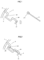
- FIG. 1 is an explanatory view of a hinge mechanism according an embodiment of the present invention, the hinge mechanism having an open-state holding portion.
- FIG. 1 shows a state in which a lug is attached to a rim.
- the lug 1 is brazed to the rim 3.
- the lug is fabricated by bending a wire-like member so as to have a connection attachment portion (pivot) 110 and a hook-shaped open-state holding portion 120 for holding a temple when the temple is opened. Meanwhile, an annular portion or pivot hole portion 210 is formed at an end of the temple 2.
- the lug 1 is passed, from the distal end of the open-state holding portion 120, through the pivot hole portion 210 in such a manner that the pivot hole portion 210 is held on the pivot 110.
- FIG. 2 shows a state in which the temple is opened.
- the open-state holding portion 120 is slightly bent toward the inner side of the temple so as to hold the shaft portion of the temple 2.
- the temple is fixed.
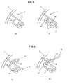
- a concave portion stopper
- the end portion of the lug is bent to form a hook-shaped holding portion, and the temple is engaged with the hook-shaped holding portion.
- the end portion of the lug may be concavely curved so as to form a concavely curved, open-state holding portion 120.
- the concavely curved, open-state holding portion 120 pinches the shaft portion of the temple 2 to thereby fix the temple.
- the temple 2 is connected to the lug by pasting the lug, from the distal end 121 of the open-state holding portion, through the pivot hole portion 210 in such a manner that the pivot hole portion 210 is held on the pivot 110 (see section (b) of FIG. 3).
- the reason why the distal end 121 of the open-state holding portion is bent outward is to provide a divergent insertion opening 122, to thereby facilitate insertion of the temple.
- the width of the insertion opening 122 is rendered slightly smaller than the shaft transverse dimension of the temple (diameter when the temple has a cylindrical shape).
- FIG. 4 shows two cross sections of the open-state holding portion and the shaft of the temple.
- the insertion opening 122 is formed to have a width slightly smaller than the size of the temple. Therefore, when the temple is inserted into the open-state holding portion 120, the temple is pressed into the open-state holding portion 120 (see section (a)). Since the insertion opening 122 of the lug is widened because of elasticity of the material thereof, the temple can be easily inserted (see section (b)). Since the temple is completely inserted into the open-state holding portion, play is eliminated. When the temple is closed, the template can be easily removed from the holding portion by virtue of elasticity of the lug.
- the lug having a concavely curved, open-state holding portion may be formed in the shape shown in FIG. 5.
- the above-mentioned lug can hold the temple (in an open state) when it is opened, the temple has a play when it is in a closed state (when closed).
- a distal end of the lug having the shape shown in FIG. 5 is extended so as to form a holding portion for holding the temple when closed.
- FIG. 6 shows an example in which the distal end of the lug is extend to form a hook-shaped holding portion.
- the lug has an open-state holding portion 120 and a closed-state holding portion 130.
- Section (b) of FIG. 6 shows a state in which the shaft portion of the closed temple 2 is engaged with the closed-state holding portion 130.
- the closed-state holding portion 130 may have a concavely curved shape as shown in FIG. 4.
- the closed-state holding portion 130 is formed by merely extending the pivot 110 above and across the shaft portion of the lug.
- the extended portion may be wound around the shaft portion of the lug so as to stabilize the closed-state holding portion 130.
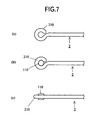
- FIG. 7 is a set of explanatory views of a turning portion of the hinge mechanism according to the embodiment of the present invention, wherein section (a) shows a temple of the present invention; section (b) is a top view showing a state in which the pivot 110 of the lug is inserted into the pivot hole of the temple; and section (c) is a side view of the temple and the pivot.
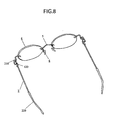
- FIG. 8 is a perspective view of rim-less spectacles having a hinge mechanism according to the present invention having an open-state holding portion.
- the wire material used in the present invention is preferably formed of a metal, such as gold alloy (e.g., heat-treated 14K), which can stably maintain a shape and has elasticity. By virtue of elasticity of metal wire material, the temple can be held stably.
- each hinge portion can be formed from a metal wire material.
- the entirety of a spectacle frame can be formed of a single metal wire material, whereby the weight of the frame can be reduced.
- gold that is preferred by clients but is heavy is used, not only the weight but also the number of metal parts other than gold parts can be reduced, whereby production cost can be lowered.
- the hinge mechanism of the present invention cannot have the same resisting characteristic as ordinary hinges. However, since a high level of stability is attained in the opened state, no practical problem arises. Moreover, the entire frame is formed of a thin wire, imparting a streamlined structure, which is preferably from the viewpoint of appearance. Furthermore, since each temple is held between two points; i.e., between the pivot and the open-state holding portion, the frame has no location where stresses concentrate, and is therefore hardly broken.
- the present invention provides the following advantageous effects.
Abstract
Description
- Screw-less hinge mechanisms formed of a single metal material can be realized.
- A light and simple design is possible.
- Temples can be stably held in an open or closed state without provision of special measures, such as resin, for high mechanisms.
- The structure of lugs is simple, and replacement of temples is easy.
Claims (3)
- A hinge mechanism for spectacles in which a temple and a lug are both formed of a wire-like metal material; an end of the temple is formed into an annular shape so as to define a pivot hole; a pivot portion of the lug formed through bending the wire-like material of the lug is inserted into the pivot hole whereby turning motion of the temple is enabled; and the lug is extended from the pivot portion along the temple and is bent so that a distal end portion of the lug is located on the inner side of the opened temple, to thereby form a temple-open-state holding portion for preventing the opened temple from turning inward.
- A hinge mechanism for spectacles according to claim 1, wherein a concave portion for receiving the temple is formed on the temple-open-state holding portion.
- A hinge mechanism for spectacles according to claim 1, wherein a curved portion for receiving the temple is formed on the temple-open-state holding portion.
Applications Claiming Priority (1)
| Application Number | Priority Date | Filing Date | Title |
|---|---|---|---|
| PCT/JP2002/006634 WO2004003635A1 (en) | 2002-07-01 | 2002-07-01 | Spectacles hinge |
Publications (3)
| Publication Number | Publication Date |
|---|---|
| EP1519216A1 true EP1519216A1 (en) | 2005-03-30 |
| EP1519216A4 EP1519216A4 (en) | 2006-04-12 |
| EP1519216B1 EP1519216B1 (en) | 2010-10-06 |
Family
ID=29808181
Family Applications (1)
| Application Number | Title | Priority Date | Filing Date |
|---|---|---|---|
| EP02741376A Expired - Lifetime EP1519216B1 (en) | 2002-07-01 | 2002-07-01 | Spectacles hinge |
Country Status (6)
| Country | Link |
|---|---|
| US (1) | US20050251960A1 (en) |
| EP (1) | EP1519216B1 (en) |
| JP (1) | JP4202318B2 (en) |
| AU (1) | AU2002315747A1 (en) |
| DE (1) | DE60237924D1 (en) |
| WO (1) | WO2004003635A1 (en) |
Families Citing this family (6)
| Publication number | Priority date | Publication date | Assignee | Title |
|---|---|---|---|---|
| US8894200B2 (en) | 2010-06-30 | 2014-11-25 | Addo Industries, Llc | Innovative and aesthetic alternative to traditional spectacle correction |
| MY179649A (en) * | 2010-09-06 | 2020-11-11 | Ic! Berlin Brillenproduktions Gmbh | Eyeglass frame and temple |
| US8757798B2 (en) | 2012-08-31 | 2014-06-24 | Cody Air LLC | Eyewear frame |
| US10261338B2 (en) | 2015-01-15 | 2019-04-16 | Addo Industries, Llc | Eyewear comprising suspension system for nose and ears |
| USD783706S1 (en) * | 2015-04-07 | 2017-04-11 | Sener Besim | Eyeglasses |
| USD816152S1 (en) * | 2015-06-24 | 2018-04-24 | Wen-Tse HUANG | Eyeglass frame |
Citations (4)
| Publication number | Priority date | Publication date | Assignee | Title |
|---|---|---|---|---|
| WO1997023803A1 (en) * | 1995-12-22 | 1997-07-03 | Ticoline A/S | Hinge structure for eyeglasses or eyeglass frames and eyeglasses and eyeglass frames, and a method of fitting a lens into an eyeglass frame |
| WO1997043683A1 (en) * | 1996-05-16 | 1997-11-20 | Bottega D'arte In Firenze S.R.L. | Wire frame for spectacles |
| US5880807A (en) * | 1995-03-31 | 1999-03-09 | Devercelli; Pietro | Spectacle mount |
| US20020054272A1 (en) * | 1999-09-01 | 2002-05-09 | Nikon Eyewear Co., Ltd. | Eyeglasses having screwless hinges |
Family Cites Families (12)
| Publication number | Priority date | Publication date | Assignee | Title |
|---|---|---|---|---|
| JP2841164B2 (en) * | 1994-08-06 | 1998-12-24 | 株式会社ホリカワ | Rotation method and rotation mechanism for glasses |
| JP2838491B2 (en) * | 1995-03-01 | 1998-12-16 | 株式会社オナガメガネ | Eyeglass frame with oblique hinge |
| EP0762178A1 (en) * | 1995-09-06 | 1997-03-12 | Sinthesys S.r.l. | A structure for rimless spectacles of the type fashioned from wire |
| US5684559A (en) * | 1996-01-31 | 1997-11-04 | Lin; Haan-Yeou | Lens positioning device for spectacles |
| IT1286108B1 (en) * | 1996-06-18 | 1998-07-07 | Pietro Devercelli | PERFECTED HINGE FOR A GLASSES FRAME. |
| IT242021Y1 (en) * | 1996-08-05 | 2001-05-24 | Gb Srl | SHAFT FOR GLASSES WITH ELASTICIZATION CAM TO BE APPLIED SHAPE OF SHAPED WIRE. |
| US5844655A (en) * | 1997-07-14 | 1998-12-01 | Chang; Antony | Glasses with automatically extended temples |
| JP3058787U (en) * | 1998-01-29 | 1999-06-22 | 株式会社ケイテオプチカ | Glasses frame |
| US6050685A (en) * | 1999-08-05 | 2000-04-18 | Lin; Haan-Yeou | Eyeglasses without a frame |
| US6203155B1 (en) * | 2000-06-12 | 2001-03-20 | Haan-Yeou Lin | Eyeglasses |
| FR2811773B1 (en) * | 2000-07-17 | 2002-10-11 | Timon | GLASSES WITH WIRED BRANCHES |
| US6412944B1 (en) * | 2001-08-21 | 2002-07-02 | Hung-Ming Huang | Eyeglasses with coupling units for coupling temples and lenses thereof |
-
2002
- 2002-07-01 DE DE60237924T patent/DE60237924D1/en not_active Expired - Lifetime
- 2002-07-01 US US10/515,827 patent/US20050251960A1/en not_active Abandoned
- 2002-07-01 EP EP02741376A patent/EP1519216B1/en not_active Expired - Lifetime
- 2002-07-01 AU AU2002315747A patent/AU2002315747A1/en not_active Abandoned
- 2002-07-01 JP JP2004517230A patent/JP4202318B2/en not_active Expired - Lifetime
- 2002-07-01 WO PCT/JP2002/006634 patent/WO2004003635A1/en active Application Filing
Patent Citations (4)
| Publication number | Priority date | Publication date | Assignee | Title |
|---|---|---|---|---|
| US5880807A (en) * | 1995-03-31 | 1999-03-09 | Devercelli; Pietro | Spectacle mount |
| WO1997023803A1 (en) * | 1995-12-22 | 1997-07-03 | Ticoline A/S | Hinge structure for eyeglasses or eyeglass frames and eyeglasses and eyeglass frames, and a method of fitting a lens into an eyeglass frame |
| WO1997043683A1 (en) * | 1996-05-16 | 1997-11-20 | Bottega D'arte In Firenze S.R.L. | Wire frame for spectacles |
| US20020054272A1 (en) * | 1999-09-01 | 2002-05-09 | Nikon Eyewear Co., Ltd. | Eyeglasses having screwless hinges |
Non-Patent Citations (1)
| Title |
|---|
| See also references of WO2004003635A1 * |
Also Published As
| Publication number | Publication date |
|---|---|
| JP4202318B2 (en) | 2008-12-24 |
| DE60237924D1 (en) | 2010-11-18 |
| WO2004003635A1 (en) | 2004-01-08 |
| AU2002315747A1 (en) | 2004-01-19 |
| JPWO2004003635A1 (en) | 2005-10-27 |
| US20050251960A1 (en) | 2005-11-17 |
| AU2002315747A8 (en) | 2004-01-19 |
| EP1519216B1 (en) | 2010-10-06 |
| EP1519216A4 (en) | 2006-04-12 |
Similar Documents
| Publication | Publication Date | Title |
|---|---|---|
| JP4004191B2 (en) | Glasses with a screwless hinge | |
| KR100931791B1 (en) | Hinge structure used in glasses | |
| JP3058787U (en) | Glasses frame | |
| JP6749712B2 (en) | glasses | |
| EP1519216B1 (en) | Spectacles hinge | |
| WO2020116333A1 (en) | Eyeglasses | |
| EP1662295A2 (en) | Screw-less hinge for eyeglasses | |
| CN106990552B (en) | Assembled glasses and its assembly method | |
| JP4084130B2 (en) | Glasses frame | |
| US6869181B2 (en) | Lens mounting mechanism of spectacles, lens mounting member, auxiliary spectacles, and spectacles | |
| EP1217418B1 (en) | A spectacle frame and a hinge assembly for use therein | |
| JP2001324699A (en) | Structure of hinge for spectacles | |
| JP2005283620A (en) | Variable rim lock of spectacle frame and spectacle frame | |
| JP3583768B2 (en) | Glasses with screwless hinges | |
| JP3050814U (en) | Glasses frame | |
| JP2012053102A (en) | Temple connection structure for spectacle and spectacle frame | |
| JP3682036B2 (en) | Screwless hinge and glasses with it | |
| JP3007469U (en) | Coil spring type eyeglass end piece | |
| JPH11326844A (en) | Curvilineaer joint structure for spectacle frame | |
| JP2002131701A (en) | Hinge structure of spectacles | |
| JPH0616932U (en) | Hinge structure of eyeglasses | |
| JP2017122863A (en) | Hingeless spectacle frame | |
| JPH0843774A (en) | Ear bend structure of spectacles | |
| JPH0713108A (en) | Spectacles having spring type temple | |
| JP2002328342A (en) | Spectacle of preventing temple from biting into side of face skin and method used for the same |
Legal Events
| Date | Code | Title | Description |
|---|---|---|---|
| PUAI | Public reference made under article 153(3) epc to a published international application that has entered the european phase |
Free format text: ORIGINAL CODE: 0009012 |
|
| 17P | Request for examination filed |
Effective date: 20041123 |
|
| AK | Designated contracting states |
Kind code of ref document: A1 Designated state(s): CH DE FR GB LI |
|
| A4 | Supplementary search report drawn up and despatched |
Effective date: 20060301 |
|
| RIN1 | Information on inventor provided before grant (corrected) |
Inventor name: NOJI, HIROMI,FUKUI MEGANE INDUSTRY CO., LTD. Inventor name: KANOU, SEIJIC/O PARIS MIKI INC. |
|
| 17Q | First examination report despatched |
Effective date: 20070223 |
|
| GRAP | Despatch of communication of intention to grant a patent |
Free format text: ORIGINAL CODE: EPIDOSNIGR1 |
|
| GRAS | Grant fee paid |
Free format text: ORIGINAL CODE: EPIDOSNIGR3 |
|
| GRAA | (expected) grant |
Free format text: ORIGINAL CODE: 0009210 |
|
| AK | Designated contracting states |
Kind code of ref document: B1 Designated state(s): CH DE FR GB LI |
|
| REG | Reference to a national code |
Ref country code: GB Ref legal event code: FG4D |
|
| REG | Reference to a national code |
Ref country code: CH Ref legal event code: EP |
|
| REF | Corresponds to: |
Ref document number: 60237924 Country of ref document: DE Date of ref document: 20101118 Kind code of ref document: P |
|
| REG | Reference to a national code |
Ref country code: CH Ref legal event code: NV Representative=s name: RENTSCH & PARTNER |
|
| REG | Reference to a national code |
Ref country code: CH Ref legal event code: PFA Owner name: PARIS MIKI INC. Free format text: PARIS MIKI INC.#4-2, NIHONBASHI MUROMACHI 2-CHOME#CHUO-KU, TOKYO 103-0022 (JP) $ FUKUI MEGANE INDUSTRY CO., LTD.#2-11, KITANOCHO 2-CHOME#SABAE-SHI, FUKUI 916-8508 (JP) -TRANSFER TO- PARIS MIKI INC.#4-2, NIHONBASHI MUROMACHI 2-CHOME#CHUO-KU, TOKYO 103-0022 (JP) $ FUKUI MEGANE INDUSTRY CO., LTD.#2-11, KITANOCHO 2-CHOME#SABAE-SHI, FUKUI 916-8508 (JP) |
|
| PLBE | No opposition filed within time limit |
Free format text: ORIGINAL CODE: 0009261 |
|
| STAA | Information on the status of an ep patent application or granted ep patent |
Free format text: STATUS: NO OPPOSITION FILED WITHIN TIME LIMIT |
|
| 26N | No opposition filed |
Effective date: 20110707 |
|
| REG | Reference to a national code |
Ref country code: DE Ref legal event code: R097 Ref document number: 60237924 Country of ref document: DE Effective date: 20110707 |
|
| REG | Reference to a national code |
Ref country code: FR Ref legal event code: PLFP Year of fee payment: 14 |
|
| REG | Reference to a national code |
Ref country code: FR Ref legal event code: PLFP Year of fee payment: 15 |
|
| REG | Reference to a national code |
Ref country code: FR Ref legal event code: PLFP Year of fee payment: 16 |
|
| REG | Reference to a national code |
Ref country code: CH Ref legal event code: PCAR Free format text: NEW ADDRESS: BELLERIVESTRASSE 203 POSTFACH, 8034 ZUERICH (CH) |
|
| REG | Reference to a national code |
Ref country code: FR Ref legal event code: PLFP Year of fee payment: 17 |
|
| PGFP | Annual fee paid to national office [announced via postgrant information from national office to epo] |
Ref country code: DE Payment date: 20200721 Year of fee payment: 19 Ref country code: GB Payment date: 20200727 Year of fee payment: 19 Ref country code: FR Payment date: 20200721 Year of fee payment: 19 |
|
| PGFP | Annual fee paid to national office [announced via postgrant information from national office to epo] |
Ref country code: CH Payment date: 20200721 Year of fee payment: 19 |
|
| REG | Reference to a national code |
Ref country code: DE Ref legal event code: R119 Ref document number: 60237924 Country of ref document: DE |
|
| REG | Reference to a national code |
Ref country code: CH Ref legal event code: PL |
|
| GBPC | Gb: european patent ceased through non-payment of renewal fee |
Effective date: 20210701 |
|
| PG25 | Lapsed in a contracting state [announced via postgrant information from national office to epo] |
Ref country code: LI Free format text: LAPSE BECAUSE OF NON-PAYMENT OF DUE FEES Effective date: 20210731 Ref country code: GB Free format text: LAPSE BECAUSE OF NON-PAYMENT OF DUE FEES Effective date: 20210701 Ref country code: DE Free format text: LAPSE BECAUSE OF NON-PAYMENT OF DUE FEES Effective date: 20220201 Ref country code: CH Free format text: LAPSE BECAUSE OF NON-PAYMENT OF DUE FEES Effective date: 20210731 |
|
| PG25 | Lapsed in a contracting state [announced via postgrant information from national office to epo] |
Ref country code: FR Free format text: LAPSE BECAUSE OF NON-PAYMENT OF DUE FEES Effective date: 20210731 |