EP1518984A1 - Mechanische Betätigungseinheit für ein Kraftfahrzeugstürschloss, und ein Schloss mit einer solchen Betätigungseinheit - Google Patents
Mechanische Betätigungseinheit für ein Kraftfahrzeugstürschloss, und ein Schloss mit einer solchen Betätigungseinheit Download PDFInfo
- Publication number
- EP1518984A1 EP1518984A1 EP04104505A EP04104505A EP1518984A1 EP 1518984 A1 EP1518984 A1 EP 1518984A1 EP 04104505 A EP04104505 A EP 04104505A EP 04104505 A EP04104505 A EP 04104505A EP 1518984 A1 EP1518984 A1 EP 1518984A1
- Authority
- EP
- European Patent Office
- Prior art keywords
- door
- unit
- lock
- principal
- inhibiting device
- Prior art date
- Legal status (The legal status is an assumption and is not a legal conclusion. Google has not performed a legal analysis and makes no representation as to the accuracy of the status listed.)
- Granted
Links
- 230000002401 inhibitory effect Effects 0.000 claims abstract description 27
- 230000007246 mechanism Effects 0.000 claims abstract description 25
- 230000009471 action Effects 0.000 claims abstract description 15
- 230000004913 activation Effects 0.000 claims abstract description 11
- 230000009849 deactivation Effects 0.000 claims description 9
- 230000000284 resting effect Effects 0.000 claims 1
- 239000000463 material Substances 0.000 description 3
- 230000008878 coupling Effects 0.000 description 2
- 238000010168 coupling process Methods 0.000 description 2
- 238000005859 coupling reaction Methods 0.000 description 2
- 230000002093 peripheral effect Effects 0.000 description 2
- 230000003213 activating effect Effects 0.000 description 1
- 238000005452 bending Methods 0.000 description 1
- 230000005540 biological transmission Effects 0.000 description 1
- 230000000903 blocking effect Effects 0.000 description 1
- 230000000295 complement effect Effects 0.000 description 1
- 239000007769 metal material Substances 0.000 description 1
- 238000012986 modification Methods 0.000 description 1
- 230000004048 modification Effects 0.000 description 1
Images



Classifications
-
- E—FIXED CONSTRUCTIONS
- E05—LOCKS; KEYS; WINDOW OR DOOR FITTINGS; SAFES
- E05B—LOCKS; ACCESSORIES THEREFOR; HANDCUFFS
- E05B81/00—Power-actuated vehicle locks
- E05B81/02—Power-actuated vehicle locks characterised by the type of actuators used
- E05B81/04—Electrical
- E05B81/06—Electrical using rotary motors
-
- E—FIXED CONSTRUCTIONS
- E05—LOCKS; KEYS; WINDOW OR DOOR FITTINGS; SAFES
- E05B—LOCKS; ACCESSORIES THEREFOR; HANDCUFFS
- E05B81/00—Power-actuated vehicle locks
- E05B81/24—Power-actuated vehicle locks characterised by constructional features of the actuator or the power transmission
- E05B81/32—Details of the actuator transmission
- E05B81/34—Details of the actuator transmission of geared transmissions
- E05B81/36—Geared sectors, e.g. fan-shaped gears
-
- E—FIXED CONSTRUCTIONS
- E05—LOCKS; KEYS; WINDOW OR DOOR FITTINGS; SAFES
- E05B—LOCKS; ACCESSORIES THEREFOR; HANDCUFFS
- E05B83/00—Vehicle locks specially adapted for particular types of wing or vehicle
- E05B83/36—Locks for passenger or like doors
-
- E—FIXED CONSTRUCTIONS
- E05—LOCKS; KEYS; WINDOW OR DOOR FITTINGS; SAFES
- E05B—LOCKS; ACCESSORIES THEREFOR; HANDCUFFS
- E05B77/00—Vehicle locks characterised by special functions or purposes
- E05B77/14—Specially controlled locking actions in case of open doors or in case of doors moved from an open to a closed position, e.g. lock-out prevention or self-cancelling
- E05B77/16—Preventing locking with the bolt in the unlatched position, i.e. when the door is open
-
- E—FIXED CONSTRUCTIONS
- E05—LOCKS; KEYS; WINDOW OR DOOR FITTINGS; SAFES
- E05B—LOCKS; ACCESSORIES THEREFOR; HANDCUFFS
- E05B77/00—Vehicle locks characterised by special functions or purposes
- E05B77/22—Functions related to actuation of locks from the passenger compartment of the vehicle
- E05B77/24—Functions related to actuation of locks from the passenger compartment of the vehicle preventing use of an inner door handle, sill button, lock knob or the like
-
- E—FIXED CONSTRUCTIONS
- E05—LOCKS; KEYS; WINDOW OR DOOR FITTINGS; SAFES
- E05B—LOCKS; ACCESSORIES THEREFOR; HANDCUFFS
- E05B77/00—Vehicle locks characterised by special functions or purposes
- E05B77/22—Functions related to actuation of locks from the passenger compartment of the vehicle
- E05B77/30—Functions related to actuation of locks from the passenger compartment of the vehicle allowing opening by means of an inner door handle, even if the door is locked
Definitions
- the present invention relates to a mechanical actuation unit of a lock for a door of a motor vehicle.
- locks are mounted, generally, inside a relative door in a position suitable to interact with a lock striker, which is integral with a fixed upright delimiting the door compartment to be closed with said door.
- the locks comprise a closing mechanism designed to couple in a releasable way with the lock striker to determine closing of the door, and a mechanical actuation unit actuated by an inside handle and by an outside handle of the door to cause release of the closing mechanism from the lock striker respectively from inside the passenger compartment and from outside the vehicle.
- the mechanical actuation unit comprises a principal inhibiting device, which can be selectively activated from outside the motor vehicle by a key or remote control, or from inside the passenger compartment by means of a knob or by means of the inside handle, to make actuation ineffective on the outside handle to inhibit opening of the door from the outside, thereby producing an external safety function.
- the mechanical actuation unit has an internal control lever, which is shaped in such as way as to interact with a relay element of the principal inhibiting device to activate and deactivate said principal inhibiting device by rotating respectively in opposite directions.
- the mechanical actuation unit also comprises an auxiliary inhibiting device, which can be activated selectively to make actuation of the inside handle ineffective and thus inhibit opening of the door from the inside.
- Actuation of the auxiliary inhibiting device also prevents deactivation of the principal inhibiting device, thus producing an internal safety function (commonly indicated with the name "dead lock") in addition to the external safety function, for the purpose of preventing fraudulent opening of the lock by tools inserted into the passenger compartment from the outside, for example between the window and the body of the door, when the vehicle is left unattended.
- the elements of the inhibiting devices are subject to unavoidable breakages if the internal control lever is forced to deactivate the principal inhibiting device when the latter is blocked by the auxiliary inhibiting device.
- the object of the present invention is to produce a mechanical actuation unit of a lock for a door of a motor vehicle, which enables the aforesaid problems to be solved in a simple and inexpensive way and, preferably, enables activation of the principal inhibiting device to be prevented when the door is open.
- a mechanical actuation unit of a lock for a door of a motor vehicle comprising a closing mechanism designed to couple in a releasable way with a lock striker to determine closing of said door; said mechanical actuation unit comprising:
- a lock is produced for a door of a motor vehicle, defined in claim 13.
- number 1 indicates as a whole a mechanical actuation unit of a lock 2 (shown partially) for a door (not shown) of a motor vehicle (not shown).
- the lock 2 is part of a centralized locking system of the doors of a motor vehicle, the operation of which is managed in a known way, not shown, by the electrical system of said motor vehicle, and is designed to interact in a known way with a lock striker 3 (the trace of which is shown with a dashed line in Figure 3) integral with an upright (not shown) of the door compartment to be closed with the door.
- the lock 2 comprises a supporting body 4 (partially shown) designed to be fixed rigidly to the door of the motor vehicle and defining two compartments 5, 6, which are separated from each other by a wall 7 of the body 4 and are closed by respective metallic plates (not shown) essentially parallel with the wall 7.
- the compartment 5 houses a closing mechanism 8 of a per se known type, which constitutes part of the lock 2 and is designed to couple in a releasable way with the lock striker 3 to determine closing of the door.
- the body 4 defines an internal sliding groove 11 to guide the lock striker 3 along an essentially rectilinear direction 12 inside the compartment 5 towards the mechanism 8 starting from an opening 13 produced on a side wall 14 of said body 4.
- the opening 13 defines the extension of a slot (not shown) produced on the metallic closing plate of the compartment 5 along the direction 12 at the level of the groove 11, and is disposed, in use, at the level of an angular opening (not shown) produced in the body of the door to allow entry of the lock striker 3 in the compartment 5.
- the mechanism 8 comprises a fork 15 and a dog 16 hinged about respective cylindrical pins 17 and 18, which extend in fixed positions through the wall 7 along respective axes A, B parallel to each other and orthogonal to the direction 12.
- the fork 15 is constituted by a shaped metallic plate coated in plastic material, is hinged at the level of an intermediate portion thereof about the pin 17 and has a peripheral C-shaped seat 20 designed to receive the lock striker 3 and delimited laterally by a pair of teeth 21, 22.
- the fork 15 is subject in a known way to the return action of a helical spring 23 ( Figures 4 and 5) wound around the pin 17 and constrained, at the ends thereof, to an appendage 24 of said fork 15 and to a stop carried by the body 4 (not shown); in particular, the fork 15 is thrust by the spring 23 towards an opening position ( Figure 4), wherein it is disposed laterally with its tooth 21 against a stop 25 carried by the wall 14 at the side of the opening 13 and enables engagement and disengagement of the lock striker 3 in/from its seat 20.
- a helical spring 23 Figures 4 and 5
- the dog 16 is constituted by a shaped metallic plate coated with plastic material extending on the same plane as the fork 15 and on one side thereof.
- the dog 16 has a terminal projection 26, which is designed to couple against the tooth 21 of the fork 15, to block it in a releasable way in the closing position, and is thrust by a helical spring 27 to rotate about the axis B towards the fork 15.
- the dog 16 is fixed to an actuating arm 28, preferably produced in plastic material and defined by an elongated plate, which extends radially with respect to the pin 18, is housed in the compartment 6 and rotates together with the dog 16 about the pin 18 on a plane orthogonal to the axis B.
- the arm 28 has a face 29 extending from the axial part opposite the dog 16 and carrying a projection 30, which protrudes parallel to the axis B and comprises two opposed terminal portions 31, 32 positioned side by side along the face 29.
- the portion 31 assumes a position wherein it can receive from the unit 1 thrust forces designed to cause release of the mechanism 8 from the lock striker 3 and thus open the door.
- the unit 1 is housed in the compartment 6 and is controllable by means of manually controlled movable elements associated with the door of the motor vehicle, such as the inside and outside handles (not shown), by means of a key unit (not shown) carried by the door on the outside of the motor vehicle, and/or by means of an electrical actuator unit (not shown) constituting part of the lock 2.
- the unit 1 comprises an opening mechanism 33 constituted by two opening devices 34, 35, which are disposed parallel to each other, are controlled to cause release of the mechanism 8 from the lock striker 3 following manual action by a user respectively on the outside handle and on the inside handle of the door and comprises respective connecting thrust rods 36, 37 designed to interact with the projection 30, to disengage the dog 16 from the fork 15.
- the connecting rods 36, 37 are defined by plates lying on planes orthogonal to the axes A and B and superimposed on each other and have an elongated shape in a transverse direction to the arm 28.
- the connecting rods 36, 37 comprise respective ends 38, 39 facing the projection 30 and shaped in a manner complementary to the shape of the portion 31, and respective ends 40, 41, opposite the ends 38, 39 and rotating about respective hinge axes C and D movable and parallel to the axes A and B.
- the connecting rods 36, 37 are movable separately from each other in the respective planes thereof starting from a reversed position, wherein the ends 40, 41 are disposed against a stop wall (not shown) laterally delimiting the compartment 6 of the body 4, towards an advanced position towards the projection 30, against the elastic action of respective helical springs 42, 43 (partially shown in Figure 4) wound around a cylindrical pin 44, which extends in a cantilever fashion from the wall 7 parallel to the pins 17, 18 and is disposed on the side of the connecting rods 36, 37 in a position spaced from said connecting rods 36, 37.
- the connecting rods 36, 37 delimit respective slots 45, 46, which are elongated along respective directions E and F orthogonal to the axes C and D and transverse to the arm 28 and house respective disks 47, 48, each disposed on the same plane as the relative connecting rod 36, 37.
- the disks 47, 48 engage the slots 45, 46 in a sliding manner to guide the relative connecting rods 36, 37 along the directions E and F between the aforesaid reversed and advanced positions and are coupled to the body 4 so as to rotate eccentric, separately from each other, about the same fixed axis G parallel to the axis B.
- the lateral surfaces of the disks 47, 48 define respective cams, as they exert a transverse thrust on the surfaces delimiting the relative slots 45, 46, during rotation about the axis G, to direct the advance trajectories of the connecting rods 36, 37, defined by the directions E and F, respectively about the axes C and D with respect to the position of the projection 30, as shall be better described hereunder.
- an external control lever 51 which is defined by a plate essentially shaped with a circular sector, lying on a plane parallel to the plane of the connecting rod 36 and disposed in an intermediate position between said connecting rod 36 and the metallic plate closing the compartment 6.
- the lever 51 comprises a terminal coupling portion, hinged about the end of the pin 44 about an axis H parallel to the axes A, B and C, and two appendages 54, 55 spaced angularly from each other about said axis H.
- the appendage 54 is hinged at the end 40 of the connecting rod 36 about the axis C, while the appendage 55 is connected, in use, to the outside handle of the door, in a way not shown (for example by interposing a Bowden cable transmission) and so that the lever 51, following operation of said outside handle, rotates about the axis H in a direction L of rotation against the elastic action exerted by the spring 42 on the connecting rod 36, to thrust the connecting rod 36 towards its advanced position.
- the opening device 35 comprises, moreover, a relay lever 57 facing the wall 7, produced in metallic material, L-shaped and comprising an intermediate portion 58 which is hinged to the pin 44 to enable the lever 57 to rotate about the axis H.
- the lever 57 comprises, moreover, a pair of arms 59, 60, which extend in a cantilever fashion from the portion 58 and radially with respect to the axis H.
- the arm 59 is interposed axially between the connecting rod 37 and the wall 7 and is hinged, at its free end, to the end 41 of the connecting rod 37 about the axis D, while the arm 60 extends in a position side by side with the connecting rods 36, 37 towards the pin 18 and carries in a cantilever fashion, at the free end thereof, a tooth 61, which projects in a direction parallel to the axis H in the opposite direction to the wall 7.
- the device 35 is controlled by an internal control lever 62 comprising an intermediate portion 64, which is hinged by means of a pin 63 ( Figure 1) to a metallic supporting bracket fixed to the body 4 (not shown), to allow the lever 62 to rotate about an axis M orthogonal to the axis H.
- the lever 62 also comprises two arms 65, 66, which extend in a cantilever fashion from the portion 64 in positions diametrically opposite each other, which together make the lever 62 essentially C-shaped and terminate with respective thrust teeth 67, 68 spaced apart from each other in a direction parallel to the axis M.
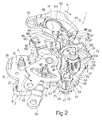
- the lever 62 also comprises a radial appendage 70 extending in a cantilever fashion from the arm 66 and connected, in use, to the inside handle of the door, in a way not shown, and is rotatable, following activation of said inside handle, about the axis M in a direction N of rotation along an opening travel path starting from a position at rest (figure 2), wherein the teeth 61, 67 are facing each other and adjacent in a tangential direction with respect to the axes H and M.
- the unit 1 also comprises a principal inhibiting device 73, which can be activated selectively to make operation of the outside handle of the door ineffective and to inhibit opening of the door from the outside, producing an external safety function of the lock 2.
- the device 73 comprises a disk 47 and a superimposed actuation element 74, coaxial and angularly integral with said disk 47.
- the disk 47 rotates about the axis G between a first end of travel position (not shown) wherein the connecting rod 36 is directed with the end 38 aligned with the portion 31 of the projection 30 along the direction E, and a second end of travel position (figure 1), wherein the trajectory of advance of the connecting rod 36, defined by the direction E, extends to the side of the projection 30.
- the actuation element 74 comprises two externally toothed sectors 75, 76 ( Figure 2), which extend on a plane orthogonal to the axis G, are diametrically opposite each other and can be actuated to cause rotation of the element 74 about the axis G.
- the sector 75 meshes with a pinion actuated by an electrical actuator of the lock 2 (not shown), has a diameter greater than the diameter of the sector 76 and defines a circumferential groove 77 ( Figure 1) produced on a face axially opposite with respect to the disk 47 and to the connecting rod 36.
- the sector 76 receives movement from a relay lever 79 ( Figures 2 and 4) constituting part of the device 73 and defined by a shaped plate extending on the same plane as the sectors 75,76.
- the lever 79 comprises an intermediate portion 80, which is hinged to the pin 44, to allow rotation of the lever 79 about the axis H, is axially facing the lever 51, carries in a cantilever fashion a toothed sector 81 meshing with the sector 76 and has a peripheral seat 82 engaged with circumferential clearance by a projection 83.
- the projection 83 constitutes part of a control lever 84, which is hinged to the pin 44 about the axis H in an intermediate axial position between the levers 57 and 79 and is actuated in a known way, not describe in detail, by the key unit of the door, to rotate the lever 79 and engage/disengage the external safety function.
- the lever 79 also comprises an arm, 85, which is C-shaped and is coupled to the body 4 by means of a helical spring 86 defining a dead positioning point, beyond which the lever 79 rotates selectively in two stable reference positions defined by respective end of travel stops (not shown) and corresponding to the first and second end of travel position of the disk 47.
- the arm 85 comprises a portion 87 extending radially from the portion 80 and a subsequent circumferential portion 88, which terminates with an end 89 coupling with the internal control lever 62.
- the end 89 has a U-shaped seat 90 defined by a radial shoulder 91 with respect to the axis H and by two circumferential protrusions 92 with respect to said axis H, and carries in a cantilever fashion a tooth 94 on a face thereof orthogonal to the axis H and facing the lever 62.
- the tooth 94 is disposed in contact with the tooth 68 in a direction tangential to the axes H and M to receive thrust from the lever 62 aimed at engaging the external safety function following a control from inside the passenger compartment, for example on the inside handle of the door.
- the lever rotates starting from its position at rest in the direction opposite the direction N towards an actuation position of the principal inhibiting device 73, that is in the opposite direction to the opening travel path described above, and causes rotation of the lever 79 in a direction P of rotation, to take the disk 47 to its aforesaid second end of travel position, simultaneously moving the tooth 67 away from the tooth 61.
- the tooth 94 is forced against the tooth 68 by the spring 71, which comprises an intermediate cylindrical helical stretch (not visible in the attached figures) wound around the pin 63, and two opposed terminal branches 96, 97.
- the branch 96 is constrained to the arm 66, while the branch 97 comprises an intermediate rectilinear stop portion 98, which is disposed against the shoulder 91 in a direction tangential to the axes H and M, is held engaged in the seat 90 by the protrusions 92 and is designed to transfer, from the lever 62 to the lever 79, thrusts aimed at disengaging the external safety function following a control from inside the passenger compartment, for example on the inside handle of the door.
- the branch 97 also comprises a terminal rectilinear stop portion 100, which is parallel to the portion 98, is connected to said portion 98 by means of a transverse portion 101, and is designed to cooperate positioned against the portion 32 of the projection 30 when the fork 15 is disposed in its opening position.
- the projection 26 of the dog 16 is side by side with the tooth 22 of the fork 16 (in a way not shown), while the arm 28 is reversed with respect to the connecting rods 36, 37, in a position wherein the portion 32 intercepts the trajectory of the portion 100 during any rotation of the lever 79 in the direction P to prevent the external safety function from being engaged.
- the unit 1 also comprises an auxiliary inhibiting device 103, which can be activated selectively to make actuation of the inside handle of the door ineffective and inhibit opening of the door from the inside, producing an internal safety function of the lock 2, normally indicated with the term "dead lock".
- auxiliary inhibiting device 103 which can be activated selectively to make actuation of the inside handle of the door ineffective and inhibit opening of the door from the inside, producing an internal safety function of the lock 2, normally indicated with the term "dead lock".
- the device 103 comprises the disk 48 and an actuation element 104, which is superimposed on and coaxial to the element 74 and is designed to rotate the disk 48 about the axis G analogously to the action performed by the element 74 on the disk 47.
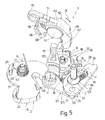
- the end 39 of the connecting rod 37 in a first end of travel position of the disk 48, is aligned with the portion 31 along the direction F and is able to thrust the projection 30 to rotate the dog 16 and disengage said dog 16 from the fork 15, so that the internal safety function is disengaged (figure 1), while in a second end of travel position of the disk 48, the end 39 translates towards its advanced position without encountering the projection 30 and, therefore, without being able to cooperate with the dog 16, so that the internal safety function is engaged (figure 5).
- the actuation element 104 is coupled in an angularly fixed way to the disk 48 by means of a cylindrical pin 105, which extends through the element 74 and is hinged at the wall 7 to the body 6 about the axis G.
- the element 54 carries in a cantilever fashion a stop tooth 107 extending parallel to the axis G towards the sector 75 and comprises a sector 108 with external toothing (figure 2), which can be actuated by an electrical actuator (not shown) to cause rotation of the element 104 about the axis G between a first configuration ( Figure 1), wherein the disk 48 is disposed in its first end of travel position and the tooth 107 engages the groove 77 with clearance, and a second configuration (not shown), wherein the disk 48 is disposed in its second end of travel position and the tooth 107 is disposed radially against the portion 80 of the lever 79.
- the tooth 107 engages a stop seat 109 (figure 2) defined circumferentially by the portion 87 and by the sector 81, to block rotation of the lever 79 in the opposite direction to the direction P when the external safety function is engaged, in order to prevent this external safety function from being disengaged by means of tools inserted into the passenger compartment from the outside, for example between the window and the body of the door, when the motor vehicle is left unattended.
- a stop seat 109 (figure 2) defined circumferentially by the portion 87 and by the sector 81, to block rotation of the lever 79 in the opposite direction to the direction P when the external safety function is engaged, in order to prevent this external safety function from being disengaged by means of tools inserted into the passenger compartment from the outside, for example between the window and the body of the door, when the motor vehicle is left unattended.
- the fork 15 rotates towards the closing position thereof, wherein it is stopped by the dog 16 ( Figure 3).
- the projection 30 is disposed in a position adjacent to the connecting rods 36, 37 and aligned with the ends 38, 39 along the directions E and F, so that it is possible to control release of the mechanism 8 from the lock striker 3 by operating the levers 62 or 51 respectively by means of the inside or the outside handles of the door.
- activation of the device 103 from outside the motor vehicle by rotation of the sector 108 causes rotation of the connecting rod 37 about the axis D to divert the trajectory of advance defined by the direction F, so that the opening travel path of the internal control lever 62 and translation of the connecting rod 37 are made ineffective, producing the internal safety function.
- activation of the device 103 causes blocking of the device 73 by means of engagement of the tooth 107 in the seat 109 and thereby prevents deactivation of the internal safety function from inside the passenger compartment.
- lever 62 and the end 89 of the lever 79 have a relatively simple shape, are hence relatively simple to produce and to mount and, in particular, are not subject to risks of interference or of disengagement during their movement during activation/deactivation of the device 73.
- any forcing on the lever 62 merely causes the spring 71 to bend, without the risk of breakages of the components of the unit 1.
- the configuration of the spring 71 and of the levers 62, 79 enables relatively low overall dimensions and a relatively low number of pieces to be obtained.
- the presence of the portion 100 designed to cooperate with the projection 30 enables activation of the device 73 to be prevented when the door is open.
- the lock 2 may be modular, or the unit 1 and the mechanism 8 may be mounted on separate supporting bodies.
- the lock 2 may be fixed to the upright of the door compartment and interact with a lock striker carried by the door.
- the unit 1 may be produced without the device 103, or the device 103 may be produced without the tooth 107 and perform a "child safety" function, instead of the "dead lock” function.
- the movable manual control elements of the levers 62 and 51 may be defined by push-buttons of the door, rather than by handles.
- the spring 71 may vary in type to and, in particular, the branch 97 may differ in shape from those shown purely by way of example.
Landscapes
- Lock And Its Accessories (AREA)
Applications Claiming Priority (2)
| Application Number | Priority Date | Filing Date | Title |
|---|---|---|---|
| ITTO20030723 ITTO20030723A1 (it) | 2003-09-19 | 2003-09-19 | Gruppo di azionamento meccanico di una serratura per una portiera di un autoveicolo e serratura provvista di tale |
| ITTO20030723 | 2003-09-19 |
Publications (2)
| Publication Number | Publication Date |
|---|---|
| EP1518984A1 true EP1518984A1 (de) | 2005-03-30 |
| EP1518984B1 EP1518984B1 (de) | 2016-12-07 |
Family
ID=34179357
Family Applications (1)
| Application Number | Title | Priority Date | Filing Date |
|---|---|---|---|
| EP04104505.5A Expired - Lifetime EP1518984B1 (de) | 2003-09-19 | 2004-09-17 | Mechanische Betätigungseinheit für ein Kraftfahrzeugtürschloss, und ein Schloss mit einer solchen Betätigungseinheit |
Country Status (3)
| Country | Link |
|---|---|
| EP (1) | EP1518984B1 (de) |
| BR (1) | BRPI0403977B1 (de) |
| IT (1) | ITTO20030723A1 (de) |
Cited By (3)
| Publication number | Priority date | Publication date | Assignee | Title |
|---|---|---|---|---|
| US11220850B2 (en) * | 2015-09-29 | 2022-01-11 | Magna Closures S.P.A. | Automotive latch with pulley for flexible cable routing |
| US20230243193A1 (en) * | 2020-04-16 | 2023-08-03 | Kiekert Aktiengesellschaft | Motor vehicle lock, in particular motor vehicle door lock |
| CN117605361A (zh) * | 2023-12-29 | 2024-02-27 | 武汉佳特汽车科技有限公司 | 汽车用前门锁 |
Citations (4)
| Publication number | Priority date | Publication date | Assignee | Title |
|---|---|---|---|---|
| GB2259734A (en) * | 1991-09-17 | 1993-03-24 | Bocklenberg & Motte Bomoro | Vehicle door latch systems |
| EP0632178A1 (de) * | 1993-05-21 | 1995-01-04 | ROLTRA MORSE S.p.A. | Kraftfahrzeugtürschloss |
| US5921595A (en) * | 1995-05-24 | 1999-07-13 | Kiekert Ag | Motor-vehicle door latch with single-handle inside actuation |
| EP1213422A2 (de) * | 2000-11-29 | 2002-06-12 | Meritor Light Vehicle Systems (UK) Ltd | Schlossvorrichtung |
-
2003
- 2003-09-19 IT ITTO20030723 patent/ITTO20030723A1/it unknown
-
2004
- 2004-09-17 EP EP04104505.5A patent/EP1518984B1/de not_active Expired - Lifetime
- 2004-09-17 BR BRPI0403977-7A patent/BRPI0403977B1/pt not_active IP Right Cessation
Patent Citations (4)
| Publication number | Priority date | Publication date | Assignee | Title |
|---|---|---|---|---|
| GB2259734A (en) * | 1991-09-17 | 1993-03-24 | Bocklenberg & Motte Bomoro | Vehicle door latch systems |
| EP0632178A1 (de) * | 1993-05-21 | 1995-01-04 | ROLTRA MORSE S.p.A. | Kraftfahrzeugtürschloss |
| US5921595A (en) * | 1995-05-24 | 1999-07-13 | Kiekert Ag | Motor-vehicle door latch with single-handle inside actuation |
| EP1213422A2 (de) * | 2000-11-29 | 2002-06-12 | Meritor Light Vehicle Systems (UK) Ltd | Schlossvorrichtung |
Cited By (4)
| Publication number | Priority date | Publication date | Assignee | Title |
|---|---|---|---|---|
| US11220850B2 (en) * | 2015-09-29 | 2022-01-11 | Magna Closures S.P.A. | Automotive latch with pulley for flexible cable routing |
| US20230243193A1 (en) * | 2020-04-16 | 2023-08-03 | Kiekert Aktiengesellschaft | Motor vehicle lock, in particular motor vehicle door lock |
| US12385293B2 (en) * | 2020-04-16 | 2025-08-12 | Kiekert Ag | Motor vehicle lock, in particular motor vehicle door lock |
| CN117605361A (zh) * | 2023-12-29 | 2024-02-27 | 武汉佳特汽车科技有限公司 | 汽车用前门锁 |
Also Published As
| Publication number | Publication date |
|---|---|
| BRPI0403977A (pt) | 2005-06-14 |
| BRPI0403977B1 (pt) | 2015-07-07 |
| EP1518984B1 (de) | 2016-12-07 |
| ITTO20030723A1 (it) | 2005-03-20 |
Similar Documents
| Publication | Publication Date | Title |
|---|---|---|
| EP2090468B1 (de) | Handschuhfachanordnung für das Armaturenbrett eines Kraftfahrzeugs | |
| CA2376040C (en) | Vehicle door latch assembly | |
| US5423582A (en) | Power-assist motor-vehicle door latch | |
| US6045168A (en) | Door latch with improved double lock | |
| EP3421702B1 (de) | Fahrzeugtürgriffanordnung | |
| GB2458567A (en) | Door latch in a motor vehicle | |
| US11377882B2 (en) | Motor vehicle lock | |
| US4468941A (en) | Electric locking device, particularly for an automobile hood | |
| US12196002B2 (en) | Latch apparatus | |
| EP0710755B2 (de) | Elektrisch betätigtes Autotürschloss | |
| US9376843B2 (en) | Position holding device for rotating lever and vehicle door lock device provided with said position holding device for rotating lever | |
| US11566454B2 (en) | Motor vehicle lock | |
| EP1518984B1 (de) | Mechanische Betätigungseinheit für ein Kraftfahrzeugtürschloss, und ein Schloss mit einer solchen Betätigungseinheit | |
| AU2022445508B2 (en) | Latch apparatus | |
| US20220186525A1 (en) | Latch apparatus | |
| EP3771790B1 (de) | Schloss | |
| EP0492288B1 (de) | Einrichtung für die Bedienung eines Fahrzeugschlosses | |
| EP1512815B1 (de) | Schloss für eine Kraftfahrzeugtür | |
| EP0712985B1 (de) | Kraftfahrzeug-Türschloss | |
| EP3061894B1 (de) | Automatisches sicherheitsschloss | |
| CN105026668A (zh) | 汽车门锁 | |
| EP1290301B1 (de) | Verriegelungsvorrichtung und -verfahren | |
| CZ296205B6 (cs) | Zarízení k ovládání zámku dverí, zejména dverí vozidel | |
| HK40111110A (zh) | 闩锁设备 | |
| CN120251012A (zh) | 一种车门锁 |
Legal Events
| Date | Code | Title | Description |
|---|---|---|---|
| PUAI | Public reference made under article 153(3) epc to a published international application that has entered the european phase |
Free format text: ORIGINAL CODE: 0009012 |
|
| AK | Designated contracting states |
Kind code of ref document: A1 Designated state(s): AT BE BG CH CY CZ DE DK EE ES FI FR GB GR HU IE IT LI LU MC NL PL PT RO SE SI SK TR |
|
| AX | Request for extension of the european patent |
Extension state: AL HR LT LV MK |
|
| 17P | Request for examination filed |
Effective date: 20050929 |
|
| AKX | Designation fees paid |
Designated state(s): DE FR IT |
|
| 17Q | First examination report despatched |
Effective date: 20120410 |
|
| REG | Reference to a national code |
Ref country code: DE Ref legal event code: R079 Ref document number: 602004050434 Country of ref document: DE Free format text: PREVIOUS MAIN CLASS: E05B0065200000 Ipc: E05B0083360000 |
|
| GRAP | Despatch of communication of intention to grant a patent |
Free format text: ORIGINAL CODE: EPIDOSNIGR1 |
|
| RIC1 | Information provided on ipc code assigned before grant |
Ipc: E05B 15/04 20060101ALI20160527BHEP Ipc: E05B 77/30 20140101ALI20160527BHEP Ipc: E05B 83/36 20140101AFI20160527BHEP |
|
| INTG | Intention to grant announced |
Effective date: 20160624 |
|
| GRAS | Grant fee paid |
Free format text: ORIGINAL CODE: EPIDOSNIGR3 |
|
| GRAA | (expected) grant |
Free format text: ORIGINAL CODE: 0009210 |
|
| RAP1 | Party data changed (applicant data changed or rights of an application transferred) |
Owner name: MAGNA CLOSURES S.P.A. |
|
| AK | Designated contracting states |
Kind code of ref document: B1 Designated state(s): DE FR IT |
|
| REG | Reference to a national code |
Ref country code: DE Ref legal event code: R096 Ref document number: 602004050434 Country of ref document: DE |
|
| PG25 | Lapsed in a contracting state [announced via postgrant information from national office to epo] |
Ref country code: IT Free format text: LAPSE BECAUSE OF FAILURE TO SUBMIT A TRANSLATION OF THE DESCRIPTION OR TO PAY THE FEE WITHIN THE PRESCRIBED TIME-LIMIT Effective date: 20161207 |
|
| REG | Reference to a national code |
Ref country code: DE Ref legal event code: R097 Ref document number: 602004050434 Country of ref document: DE |
|
| PLBE | No opposition filed within time limit |
Free format text: ORIGINAL CODE: 0009261 |
|
| STAA | Information on the status of an ep patent application or granted ep patent |
Free format text: STATUS: NO OPPOSITION FILED WITHIN TIME LIMIT |
|
| 26N | No opposition filed |
Effective date: 20170908 |
|
| REG | Reference to a national code |
Ref country code: FR Ref legal event code: ST Effective date: 20180531 |
|
| PG25 | Lapsed in a contracting state [announced via postgrant information from national office to epo] |
Ref country code: FR Free format text: LAPSE BECAUSE OF NON-PAYMENT OF DUE FEES Effective date: 20171002 |
|
| PGFP | Annual fee paid to national office [announced via postgrant information from national office to epo] |
Ref country code: DE Payment date: 20190903 Year of fee payment: 16 |
|
| REG | Reference to a national code |
Ref country code: DE Ref legal event code: R119 Ref document number: 602004050434 Country of ref document: DE |
|
| PG25 | Lapsed in a contracting state [announced via postgrant information from national office to epo] |
Ref country code: DE Free format text: LAPSE BECAUSE OF NON-PAYMENT OF DUE FEES Effective date: 20210401 |