EP1518720A1 - Radachse für ein Kraftfahrzeug - Google Patents
Radachse für ein Kraftfahrzeug Download PDFInfo
- Publication number
- EP1518720A1 EP1518720A1 EP03103549A EP03103549A EP1518720A1 EP 1518720 A1 EP1518720 A1 EP 1518720A1 EP 03103549 A EP03103549 A EP 03103549A EP 03103549 A EP03103549 A EP 03103549A EP 1518720 A1 EP1518720 A1 EP 1518720A1
- Authority
- EP
- European Patent Office
- Prior art keywords
- wheel
- intermediate frame
- wheel axle
- bearing bushes
- bearing
- Prior art date
- Legal status (The legal status is an assumption and is not a legal conclusion. Google has not performed a legal analysis and makes no representation as to the accuracy of the status listed.)
- Granted
Links
- 230000033001 locomotion Effects 0.000 claims description 13
- 239000000725 suspension Substances 0.000 claims description 12
- 238000005096 rolling process Methods 0.000 claims description 8
- 239000000463 material Substances 0.000 claims 1
- 230000006835 compression Effects 0.000 description 3
- 238000007906 compression Methods 0.000 description 3
- 230000000694 effects Effects 0.000 description 3
- 230000002411 adverse Effects 0.000 description 2
- 238000010521 absorption reaction Methods 0.000 description 1
- 230000005540 biological transmission Effects 0.000 description 1
- 150000001875 compounds Chemical class 0.000 description 1
- 238000010276 construction Methods 0.000 description 1
- 230000008094 contradictory effect Effects 0.000 description 1
- 230000008878 coupling Effects 0.000 description 1
- 238000010168 coupling process Methods 0.000 description 1
- 238000005859 coupling reaction Methods 0.000 description 1
- 230000001419 dependent effect Effects 0.000 description 1
- 239000007787 solid Substances 0.000 description 1
- 230000000087 stabilizing effect Effects 0.000 description 1
Images
Classifications
-
- B—PERFORMING OPERATIONS; TRANSPORTING
- B60—VEHICLES IN GENERAL
- B60G—VEHICLE SUSPENSION ARRANGEMENTS
- B60G9/00—Resilient suspensions of a rigid axle or axle housing for two or more wheels
- B60G9/02—Resilient suspensions of a rigid axle or axle housing for two or more wheels the axle or housing being pivotally mounted on the vehicle, e.g. the pivotal axis being parallel to the longitudinal axis of the vehicle
- B60G9/022—Resilient suspensions of a rigid axle or axle housing for two or more wheels the axle or housing being pivotally mounted on the vehicle, e.g. the pivotal axis being parallel to the longitudinal axis of the vehicle the axle having an imaginary pivotal point
-
- B—PERFORMING OPERATIONS; TRANSPORTING
- B60—VEHICLES IN GENERAL
- B60G—VEHICLE SUSPENSION ARRANGEMENTS
- B60G21/00—Interconnection systems for two or more resiliently-suspended wheels, e.g. for stabilising a vehicle body with respect to acceleration, deceleration or centrifugal forces
- B60G21/007—Interconnection systems for two or more resiliently-suspended wheels, e.g. for stabilising a vehicle body with respect to acceleration, deceleration or centrifugal forces means for adjusting the wheel inclination
-
- B—PERFORMING OPERATIONS; TRANSPORTING
- B60—VEHICLES IN GENERAL
- B60G—VEHICLE SUSPENSION ARRANGEMENTS
- B60G3/00—Resilient suspensions for a single wheel
- B60G3/18—Resilient suspensions for a single wheel with two or more pivoted arms, e.g. parallelogram
- B60G3/20—Resilient suspensions for a single wheel with two or more pivoted arms, e.g. parallelogram all arms being rigid
-
- B—PERFORMING OPERATIONS; TRANSPORTING
- B60—VEHICLES IN GENERAL
- B60G—VEHICLE SUSPENSION ARRANGEMENTS
- B60G2200/00—Indexing codes relating to suspension types
- B60G2200/30—Rigid axle suspensions
- B60G2200/32—Rigid axle suspensions pivoted
-
- B—PERFORMING OPERATIONS; TRANSPORTING
- B60—VEHICLES IN GENERAL
- B60G—VEHICLE SUSPENSION ARRANGEMENTS
- B60G2204/00—Indexing codes related to suspensions per se or to auxiliary parts
- B60G2204/10—Mounting of suspension elements
- B60G2204/15—Mounting of subframes
-
- B—PERFORMING OPERATIONS; TRANSPORTING
- B60—VEHICLES IN GENERAL
- B60G—VEHICLE SUSPENSION ARRANGEMENTS
- B60G2204/00—Indexing codes related to suspensions per se or to auxiliary parts
- B60G2204/40—Auxiliary suspension parts; Adjustment of suspensions
- B60G2204/41—Elastic mounts, e.g. bushings
- B60G2204/4104—Bushings having modified rigidity in particular directions
Definitions
- the invention relates bearing bushes for such a wheel axle.
- camber that is the angle, the plane of a Rades relative to the vertical at the contact point of the wheel assumes. Is the The wheel plane inclined away from the vehicle at the top, this is called a “positive fall”, otherwise from a “negative fall”.
- the wheel axle according to the invention for a motor vehicle comprises an intermediate frame or subframe, which bushings for buffered connection with having the body of a vehicle.
- the intermediate frame has while at least two mirror-symmetrically arranged to the vehicle longitudinal plane Bushings.
- the intermediate frame serves as a coupling element between the bodywork and two independent wheel suspensions for the two wheels of the wheel axle.
- the mentioned independent wheel suspensions each consist of one upper control arm and a lower control arm, said control arm each at its two ends articulated on the one hand with a wheel (steering knuckle etc.) and on the other hand connected to said intermediate frame are.
- an SLA or similar suspension possibly additional transverse or trailing arm exhibit.
- Such handlebars are used to z.
- the control arms are in Such a case preferably hinged to the intermediate frame.
- the trailing arm can e-steer either on the intermediate frame or directly on the body become.
- the wheel axle is characterized in that the bearing bushes at a non-zero inclination angle to the vehicle transverse axis lower rigidity than in all other directions when the wheel axle is mounted on a body. If therefore forces between the intermediate frame and the bodywork occur, the bushings give a compression towards the mentioned angle of inclination more than in Richtu n-gen perpendicular thereto, resulting in a dependent on the direction of force geometric Change in position between the body and the intermediate frame leads.
- the lower arm is formed longer than the upper arm, so that the independent wheel suspensions have a trapezoidal shape (English SLA: Short-long arm suspension).
- SLA Short-long arm suspension
- Such a SLA configuration has a stabilizing Enlargement of the negative camber during compression of a wheel Episode.
- the kinematics the wheel axle can be set specifically to a desired behavior.
- the conventional built-up part of the wheel axle with the upper and lower wishbones supports lateral forces and the wheel movement in the usual way. there cornering forces are primarily taken over by the lower wishbone, while the upper wishbone mainly determines the camber.
- the proposed wheel axle behaves substantially like a conventional wheel axle of the SLA type.
- the side forces are from the intermediate frame on the bushings transferred to the body. Due to their directional stiffness form the bearing bush doing a guide which the intermediate frame under influence by lateral forces to change its inclination, which in turn forces the wheels has a camber compensating effect.
- Driving dynamics can be the angle of inclination, under which the rigidity of the bearing bushes is minimal, and the ratio between minimum stiffness and the Stiffness can be adjusted in directions perpendicular to the angle of inclination.
- Inclination angle lies between 0 ° and 90 °, preferably between 5 ° and 45 °.
- the directional stiffness of the bushings can be specified in particular so be that a change in the camber in consequence rolling the bodywork is compensated during a counter-rotating wheel movement.
- a conventional wheel axle of the SLA type becomes a compensation achieved the camber, which in turn improves the road liability.
- the kinematics of the SLA axis can be designed so that when parallel Wheel movement no camber change occurs.
- axle described bearing bushes can be used, which in an "axial" direction of the primary load a smaller stiffness than in others Have directions, the bearing bushes then with the axis of minimum Stiffness under a corresponding angle of inclination between body and intermediate frames are to be arranged.
- the invention also includes special bushes for a wheel axle of described above, which are characterized in that they cavities and / or embedded foreign compounds to provide directional stiffness to achieve.
- Such bushings can then quasi arbitrary place be arranged between the body and an intermediate frame, there by its internal structure an inclined position of the axis of minimal rigidity is reached.
- bearing bushes instead of at a conventional bushings used bearing bushes are used where the force axis or connecting line between the contact surfaces Body on the one hand and intermediate frame on the other hand typically about parallel runs to the vehicle vertical axis.
- the internal structure of the invention Bushings causes despite this arrangement then a relative to the vertical oblique position of the axis of minimal rigidity.
- bearing bush of the above typically consists essentially of rubber.
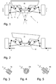
- FIG. 1 and 2 is a wheel axle according to the invention for a motor vehicle schematically reproduced in a view from behind.
- the basic structure The wheel axle corresponds to a suspension of the SLA type (Short-Long Arm suspension).
- SLA Short-Long Arm suspension
- the left in the figure wheel carrier 6 of a wheel which may be, for example, a steering knuckle, in a joint 7 connected to an upper short wishbone 8, wherein the wishbone in another joint 9 is hinged to an intermediate frame 2.
- the wheel carrier 6 is connected via a hinge 5 to a longer lower transverse link 4, the other end of the lower arm 4 in a hinge 3 at the intermediate frame 2 is articulated.
- the suspension of the right in the figure Rades takes place in the same way mirror-symmetrical to the suspension described.
- the intermediate frame 2 is via two bushings 10, 10 'at the schematically indicated body 11 of the motor vehicle supported.
- this support is carried out so that the rigidity of the bearing bushes 10, 10 'at an inclination angle ⁇ relative to the horizontal (or more precisely to the transverse axis of the vehicle or the Wheel axle) is minimal; in directions perpendicular to this angle of inclination is the Stiffness correspondingly larger.
- the ratio is between minimum and maximum stiffness of the bushes 10, 10 'about 1: 1.5 to 1:10, the stiffness being e.g. by the ratio of acting force (Newton) to resulting length change (mm) can be expressed.
- the bearing bushes 10, 10 ' When driving straight ahead of the motor vehicle, the bearing bushes 10, 10 ' essentially always symmetrically loaded, i. the two wheels or wheel carrier move up in parallel (block arrows in Figure 1) or below, or it only one wheel moves alone.
- the intermediate frame 2 thereby remains horizontal Aligns and affects the camber, i. the inclination of the wheels relative to Vertical, not.
- FIG. 3 shows a cross section through a first embodiment of a bearing bush 10a shown with directional stiffness behavior.
- the bearing bush 10a consists of a rubber cylinder with a cavity along the Cylinder axis.
- the stiffness in two mutually perpendicular directions is here and in the following figures each symbolized by arrows of different lengths.
- an externally cylindrical Bearing bush 10b are inside cavities for producing an anisotropic Stiffness provided.
- the bearing bush 10c shown in Figure 5 consists of a solid, cuboid Rubber body, which on two opposite outer surfaces through dimensionally stable plates is taken.
Landscapes
- Engineering & Computer Science (AREA)
- Mechanical Engineering (AREA)
- Vehicle Body Suspensions (AREA)
Abstract
Description
Es zeigen:
- Fig. 1
- eine schematische Ansicht einer erfindungsgemäßen Radachse im Zustand einer Geradeausfahrt;
- Fig. 2
- die Radachse von Figur 1 im Zustand einer Kurvenfahrt, und
- Fig. 3-5
- verschiedene Arten von Lagerbuchsen mit richtungsabhängiger Steifigkeit.
Claims (8)
- Radachse für ein Kraftfahrzeug, enthaltenddadurch gekennzeichnet, daßa) einen Zwischenrahmen (2), welcher Lagerbuchsen (10, 10') zur Verbindung mit der Karosserie (11) des Kraftfahrzeuges aufweist;b) für jedes Rad eine Einzelradaufhängung bestehend aus einem unteren Querlenker (8) und einem oberen Querlenker (4), wobei die Querlenker (4, 8) jeweils gelenkig mit einem Radträger (6) und dem Zwischenrahmen (2) gekoppelt sind;
die Lagerbuchsen (10, 10') im montierten Zustand unter einem Neigungswinkel (β) zur Fahrzeugquerachse eine geringere Steifigkeit aufweisen als in allen anderen Richtungen. - Radachse nach Anspruch 1,
dadurch gekennzeichnet, daß
der Neigungswinkel (β) 0° bis 90°, vorzugsweise 5° bis 45° beträgt. - Radachse nach Anspruch 1 oder 2,
dadurch gekennzeichnet, daß
der untere Querlenker (4) länger ist als der obere Querlenker (8). - Radachse nach mindestens einem der Ansprüche 1 bis 3,
dadurch gekennzeichnet, daß
die Steifigkeit der Lagerbuchsen (10, 10') derart eingestellt wird, daß eine Veränderung des Radsturzes während einer parallelen Radbewegung minimiert und ein Rollen der Karosserie während einer gegenläufigen Radbewegung kompensiert wird. - Radachse nach mindestens einem der Ansprüche 1 bis 4,
dadurch gekennzeichnet, daß
der Zwischenrahmen (2) mindestens zwei spiegelsymmetrisch zur Fahrzeuglängsebene angeordnete Lagerbuchsen (10, 10') aufweist. - Radachse nach mindestens einem der Ansprüche 1 bis 5,
dadurch gekennzeichnet, daß
die Achse weitere Querlenker, die jeweils gelenkig mit einem Radträger (6) und dem Zwischenrahmen (2) gekoppelt sind oder Längslenker, die jeweils gelenkig mit einem Radträger (6) und dem Zwischenrahmen (2) oder der Karosserie (11) gekoppelt sind, besitzt. - Lagerbuchse (10a, 10b, 10c) für eine Radachse (1) nach mindestens einem der Ansprüche 1 bis 6,
dadurch gekennzeichnet, daß
diese Hohlräume und/oder eingebettete Fremdmassen enthält, um eine richtungsabhängige Steifigkeit zu erzielen. - Lagerbuchse nach Anspruch 7,
dadurch gekennzeichnet, daß
ihr Grundmaterial Gummi ist.
Priority Applications (1)
| Application Number | Priority Date | Filing Date | Title |
|---|---|---|---|
| EP20030103549 EP1518720B1 (de) | 2003-09-25 | 2003-09-25 | Radachse für ein Kraftfahrzeug |
Applications Claiming Priority (1)
| Application Number | Priority Date | Filing Date | Title |
|---|---|---|---|
| EP20030103549 EP1518720B1 (de) | 2003-09-25 | 2003-09-25 | Radachse für ein Kraftfahrzeug |
Publications (2)
| Publication Number | Publication Date |
|---|---|
| EP1518720A1 true EP1518720A1 (de) | 2005-03-30 |
| EP1518720B1 EP1518720B1 (de) | 2013-11-13 |
Family
ID=34178596
Family Applications (1)
| Application Number | Title | Priority Date | Filing Date |
|---|---|---|---|
| EP20030103549 Expired - Lifetime EP1518720B1 (de) | 2003-09-25 | 2003-09-25 | Radachse für ein Kraftfahrzeug |
Country Status (1)
| Country | Link |
|---|---|
| EP (1) | EP1518720B1 (de) |
Cited By (3)
| Publication number | Priority date | Publication date | Assignee | Title |
|---|---|---|---|---|
| EP1738928A1 (de) * | 2005-06-29 | 2007-01-03 | Swiss Prototech AG | Radachse für einen Mähdrescher |
| GB2475310A (en) * | 2009-11-16 | 2011-05-18 | Agco Sa | Vehicle axle mounting arrangement |
| GB2475309A (en) * | 2009-11-16 | 2011-05-18 | Agco Sa | Vehicle axle mounting arrangement |
Citations (4)
| Publication number | Priority date | Publication date | Assignee | Title |
|---|---|---|---|---|
| EP0034531A1 (de) | 1980-02-13 | 1981-08-26 | Automobiles Citroen | Träger für Kraftfahrzeugachse |
| GB2270508A (en) * | 1992-09-14 | 1994-03-16 | Mclaren Cars Nv | Suspension systems |
| WO2002058949A1 (fr) | 2001-01-23 | 2002-08-01 | Societe De Technologie Michelin | Dispositif de suspension d'une roue de vehicule |
| US20020125674A1 (en) | 2000-01-25 | 2002-09-12 | Walker Peter John | Vehicle suspension system |
-
2003
- 2003-09-25 EP EP20030103549 patent/EP1518720B1/de not_active Expired - Lifetime
Patent Citations (4)
| Publication number | Priority date | Publication date | Assignee | Title |
|---|---|---|---|---|
| EP0034531A1 (de) | 1980-02-13 | 1981-08-26 | Automobiles Citroen | Träger für Kraftfahrzeugachse |
| GB2270508A (en) * | 1992-09-14 | 1994-03-16 | Mclaren Cars Nv | Suspension systems |
| US20020125674A1 (en) | 2000-01-25 | 2002-09-12 | Walker Peter John | Vehicle suspension system |
| WO2002058949A1 (fr) | 2001-01-23 | 2002-08-01 | Societe De Technologie Michelin | Dispositif de suspension d'une roue de vehicule |
Cited By (5)
| Publication number | Priority date | Publication date | Assignee | Title |
|---|---|---|---|---|
| EP1738928A1 (de) * | 2005-06-29 | 2007-01-03 | Swiss Prototech AG | Radachse für einen Mähdrescher |
| GB2475310A (en) * | 2009-11-16 | 2011-05-18 | Agco Sa | Vehicle axle mounting arrangement |
| GB2475309A (en) * | 2009-11-16 | 2011-05-18 | Agco Sa | Vehicle axle mounting arrangement |
| US8801012B2 (en) | 2009-11-16 | 2014-08-12 | Agco Sa | Vehicle axle mounting arrangement |
| US8864156B2 (en) | 2009-11-16 | 2014-10-21 | Agco Corporation | Vehicle axle mounting arrangement |
Also Published As
| Publication number | Publication date |
|---|---|
| EP1518720B1 (de) | 2013-11-13 |
Similar Documents
| Publication | Publication Date | Title |
|---|---|---|
| EP1666282B1 (de) | Radaufhänger mit Federverstellung für Kraftfahrzeuge | |
| DE19637159B4 (de) | Radaufhängung mit selbsttätiger Sturzanpassung | |
| DE19743736B4 (de) | Vorderradaufhängung | |
| DE102010061008B4 (de) | Aktive-Geometrie-Steuerung-Aufhängungssystem und Betätigungsvorrichtung zum Antreiben derselben | |
| EP3297891B1 (de) | Kraftfahrzeug mit einem achsträger | |
| DE69615476T2 (de) | Schräglenker-Hinterachse für ein Fahrzeug | |
| DE3623847C2 (de) | ||
| EP1985474B1 (de) | Sattelauflieger | |
| DE3331282A1 (de) | Radaufhaengung fuer lenkbare vorderraeder von kraftfahrzeugen | |
| DE9090175U1 (de) | Einzelradaufhängung | |
| DE2137757A1 (de) | Radaufhaengung fuer fahrzeuge | |
| DE102007054823A1 (de) | Verstellvorrichtung für Radaufhängungen | |
| WO2007087797A1 (de) | Radaufhängung für ein kraftfahrzeug | |
| DE102019202910A1 (de) | Hinterradaufhängung | |
| EP1346854B1 (de) | Radaufhängung für ein Kraftfahrzeug | |
| DE60100184T2 (de) | Radaufhängung für ein fahrzeug | |
| WO2019037947A1 (de) | Radaufhängung für ein kraftfahrzeug | |
| EP1565370B1 (de) | Schwenklager sowie mit einem solchen ausgestattete lenkachse | |
| EP0806310A2 (de) | Einzelradaufhängung für ein luftgefedertes, lenkbares Rad eines Omnibusses oder Lastkraftwagens | |
| DE102018206417A1 (de) | Radaufhängung für ein Kraftfahrzeug | |
| DE102009059029A1 (de) | Einzelradaufhängung eines insbesondere nicht lenkbaren Rades eines zweispurigen Fahrzeugs | |
| DE102019117991A1 (de) | Mehrlenker-Einzelradaufhängung und Fahrzeug | |
| EP1518720B1 (de) | Radachse für ein Kraftfahrzeug | |
| DE102017211277A1 (de) | Radaufhängung für ein Kraftfahrzeug | |
| DE2332387A1 (de) | Radaufhaengung fuer gelenkte raeder von kraftfahrzeugen |
Legal Events
| Date | Code | Title | Description |
|---|---|---|---|
| PUAI | Public reference made under article 153(3) epc to a published international application that has entered the european phase |
Free format text: ORIGINAL CODE: 0009012 |
|
| AK | Designated contracting states |
Kind code of ref document: A1 Designated state(s): AT BE BG CH CY CZ DE DK EE ES FI FR GB GR HU IE IT LI LU MC NL PT RO SE SI SK TR |
|
| AX | Request for extension of the european patent |
Extension state: AL LT LV MK |
|
| 17P | Request for examination filed |
Effective date: 20050930 |
|
| AKX | Designation fees paid |
Designated state(s): DE FR GB |
|
| 17Q | First examination report despatched |
Effective date: 20080627 |
|
| GRAP | Despatch of communication of intention to grant a patent |
Free format text: ORIGINAL CODE: EPIDOSNIGR1 |
|
| RIC1 | Information provided on ipc code assigned before grant |
Ipc: B60G 3/20 20060101AFI20130308BHEP Ipc: B60G 9/02 20060101ALI20130308BHEP Ipc: B60G 21/00 20060101ALI20130308BHEP |
|
| INTG | Intention to grant announced |
Effective date: 20130412 |
|
| GRAS | Grant fee paid |
Free format text: ORIGINAL CODE: EPIDOSNIGR3 |
|
| RAP1 | Party data changed (applicant data changed or rights of an application transferred) |
Owner name: FORD GLOBAL TECHNOLOGIES, LLC, A SUBSIDARY OF FORD |
|
| GRAA | (expected) grant |
Free format text: ORIGINAL CODE: 0009210 |
|
| AK | Designated contracting states |
Kind code of ref document: B1 Designated state(s): DE FR GB |
|
| REG | Reference to a national code |
Ref country code: GB Ref legal event code: FG4D Free format text: NOT ENGLISH |
|
| REG | Reference to a national code |
Ref country code: DE Ref legal event code: R096 Ref document number: 50314940 Country of ref document: DE Effective date: 20140109 |
|
| REG | Reference to a national code |
Ref country code: DE Ref legal event code: R097 Ref document number: 50314940 Country of ref document: DE |
|
| PLBE | No opposition filed within time limit |
Free format text: ORIGINAL CODE: 0009261 |
|
| STAA | Information on the status of an ep patent application or granted ep patent |
Free format text: STATUS: NO OPPOSITION FILED WITHIN TIME LIMIT |
|
| 26N | No opposition filed |
Effective date: 20140814 |
|
| REG | Reference to a national code |
Ref country code: DE Ref legal event code: R097 Ref document number: 50314940 Country of ref document: DE Effective date: 20140814 |
|
| REG | Reference to a national code |
Ref country code: FR Ref legal event code: PLFP Year of fee payment: 13 |
|
| PGFP | Annual fee paid to national office [announced via postgrant information from national office to epo] |
Ref country code: FR Payment date: 20150624 Year of fee payment: 13 |
|
| PGFP | Annual fee paid to national office [announced via postgrant information from national office to epo] |
Ref country code: GB Payment date: 20150825 Year of fee payment: 13 |
|
| PGFP | Annual fee paid to national office [announced via postgrant information from national office to epo] |
Ref country code: DE Payment date: 20150930 Year of fee payment: 13 |
|
| REG | Reference to a national code |
Ref country code: DE Ref legal event code: R119 Ref document number: 50314940 Country of ref document: DE |
|
| GBPC | Gb: european patent ceased through non-payment of renewal fee |
Effective date: 20160925 |
|
| REG | Reference to a national code |
Ref country code: FR Ref legal event code: ST Effective date: 20170531 |
|
| PG25 | Lapsed in a contracting state [announced via postgrant information from national office to epo] |
Ref country code: FR Free format text: LAPSE BECAUSE OF NON-PAYMENT OF DUE FEES Effective date: 20160930 Ref country code: GB Free format text: LAPSE BECAUSE OF NON-PAYMENT OF DUE FEES Effective date: 20160925 Ref country code: DE Free format text: LAPSE BECAUSE OF NON-PAYMENT OF DUE FEES Effective date: 20170401 |