EP1518521B1 - Four compartment knee - Google Patents
Four compartment knee Download PDFInfo
- Publication number
- EP1518521B1 EP1518521B1 EP04030369A EP04030369A EP1518521B1 EP 1518521 B1 EP1518521 B1 EP 1518521B1 EP 04030369 A EP04030369 A EP 04030369A EP 04030369 A EP04030369 A EP 04030369A EP 1518521 B1 EP1518521 B1 EP 1518521B1
- Authority
- EP
- European Patent Office
- Prior art keywords
- posterior
- condyles
- box
- spine
- implant
- Prior art date
- Legal status (The legal status is an assumption and is not a legal conclusion. Google has not performed a legal analysis and makes no representation as to the accuracy of the status listed.)
- Expired - Lifetime
Links
- 210000003127 knee Anatomy 0.000 title claims description 35
- 239000007943 implant Substances 0.000 claims description 45
- 238000002156 mixing Methods 0.000 claims 2
- 206010023204 Joint dislocation Diseases 0.000 description 5
- 238000005452 bending Methods 0.000 description 3
- 210000000629 knee joint Anatomy 0.000 description 3
- 210000002303 tibia Anatomy 0.000 description 3
- 210000000689 upper leg Anatomy 0.000 description 3
- 230000000694 effects Effects 0.000 description 2
- 239000000463 material Substances 0.000 description 2
- 239000000203 mixture Substances 0.000 description 2
- 229920010741 Ultra High Molecular Weight Polyethylene (UHMWPE) Polymers 0.000 description 1
- 210000000988 bone and bone Anatomy 0.000 description 1
- 239000004568 cement Substances 0.000 description 1
- 238000010276 construction Methods 0.000 description 1
- 230000006378 damage Effects 0.000 description 1
- 201000010099 disease Diseases 0.000 description 1
- 208000037265 diseases, disorders, signs and symptoms Diseases 0.000 description 1
- 208000014674 injury Diseases 0.000 description 1
- 230000003993 interaction Effects 0.000 description 1
- 238000013150 knee replacement Methods 0.000 description 1
- 210000002414 leg Anatomy 0.000 description 1
- 210000004285 patellofemoral joint Anatomy 0.000 description 1
- 238000004904 shortening Methods 0.000 description 1
- 210000003906 tibiofibular joint Anatomy 0.000 description 1
- 230000007704 transition Effects 0.000 description 1
- 230000008733 trauma Effects 0.000 description 1
Images
Classifications
-
- A—HUMAN NECESSITIES
- A61—MEDICAL OR VETERINARY SCIENCE; HYGIENE
- A61F—FILTERS IMPLANTABLE INTO BLOOD VESSELS; PROSTHESES; DEVICES PROVIDING PATENCY TO, OR PREVENTING COLLAPSING OF, TUBULAR STRUCTURES OF THE BODY, e.g. STENTS; ORTHOPAEDIC, NURSING OR CONTRACEPTIVE DEVICES; FOMENTATION; TREATMENT OR PROTECTION OF EYES OR EARS; BANDAGES, DRESSINGS OR ABSORBENT PADS; FIRST-AID KITS
- A61F2/00—Filters implantable into blood vessels; Prostheses, i.e. artificial substitutes or replacements for parts of the body; Appliances for connecting them with the body; Devices providing patency to, or preventing collapsing of, tubular structures of the body, e.g. stents
- A61F2/02—Prostheses implantable into the body
- A61F2/30—Joints
- A61F2/38—Joints for elbows or knees
- A61F2/3859—Femoral components
-
- A—HUMAN NECESSITIES
- A61—MEDICAL OR VETERINARY SCIENCE; HYGIENE
- A61F—FILTERS IMPLANTABLE INTO BLOOD VESSELS; PROSTHESES; DEVICES PROVIDING PATENCY TO, OR PREVENTING COLLAPSING OF, TUBULAR STRUCTURES OF THE BODY, e.g. STENTS; ORTHOPAEDIC, NURSING OR CONTRACEPTIVE DEVICES; FOMENTATION; TREATMENT OR PROTECTION OF EYES OR EARS; BANDAGES, DRESSINGS OR ABSORBENT PADS; FIRST-AID KITS
- A61F2/00—Filters implantable into blood vessels; Prostheses, i.e. artificial substitutes or replacements for parts of the body; Appliances for connecting them with the body; Devices providing patency to, or preventing collapsing of, tubular structures of the body, e.g. stents
- A61F2/02—Prostheses implantable into the body
- A61F2/30—Joints
- A61F2/38—Joints for elbows or knees
- A61F2/3886—Joints for elbows or knees for stabilising knees against anterior or lateral dislocations
-
- A—HUMAN NECESSITIES
- A61—MEDICAL OR VETERINARY SCIENCE; HYGIENE
- A61F—FILTERS IMPLANTABLE INTO BLOOD VESSELS; PROSTHESES; DEVICES PROVIDING PATENCY TO, OR PREVENTING COLLAPSING OF, TUBULAR STRUCTURES OF THE BODY, e.g. STENTS; ORTHOPAEDIC, NURSING OR CONTRACEPTIVE DEVICES; FOMENTATION; TREATMENT OR PROTECTION OF EYES OR EARS; BANDAGES, DRESSINGS OR ABSORBENT PADS; FIRST-AID KITS
- A61F2/00—Filters implantable into blood vessels; Prostheses, i.e. artificial substitutes or replacements for parts of the body; Appliances for connecting them with the body; Devices providing patency to, or preventing collapsing of, tubular structures of the body, e.g. stents
- A61F2/02—Prostheses implantable into the body
- A61F2/30—Joints
- A61F2/30721—Accessories
- A61F2/30734—Modular inserts, sleeves or augments, e.g. placed on proximal part of stem for fixation purposes or wedges for bridging a bone defect
- A61F2002/30736—Augments or augmentation pieces, e.g. wedges or blocks for bridging a bone defect
Definitions
- TKR range of motion
- the present invention provides a fourth articulating compartment, namely the superior posterior femoral condyles.
- All prior TKR designs ignore the superior posterior condyles.
- the articulating surface of the posterior condyles of prior TKR's continue their natural curves until the posterior condylar surface meets the interior posterior wall of the TKR fixation surface. Where the two surfaces meet, an edge is formed.
- the posterior superior edge of standard TKR's may have a small fillet. If such a TKR is able to articulate beyond 130 degrees at all, then the edge directly articulates against the tibial articulating surface which is usually made of ultra high molecular weight polyethylene (UHMWPE).
- UHMWPE ultra high molecular weight polyethylene
- the superior posterior articulating surface is achieved by first increasing the thickness of the superior posterior condylar portion of the TKR femoral component to widen the superior posterior edge of the posterior condyle. Second, the newly created surface at the superior posterior condyle is smoothly rounded to provide an articular surface with no sharp changes in the surface contours.
- the fourth articular compartment of this invention is provided in a one piece femoral design. In another embodiment, it is provided as a modular addition to an existing prior art femoral component. In another embodiment, the fourth compartment is combined with a posterior stabilized (PS) TKR design that includes a tibial post and cooperating femoral cam characterized by low engagement of the cam on the spine.
- PS posterior stabilized
- FIGS. 1,2,3 , 7 and 15 show embodiments of the femoral knee component of the present invention oriented at zero degrees of flexion. Unless otherwise noted, the geometric relationships of this invention are descriptive of a femoral knee implant in this orientation.
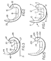
- FIG. 1 depicts an exemplary one-piece femoral knee implant 1 according to the present invention.
- the implant 1 includes arcuate medial 2 and lateral (not shown) condyles joined together at their anterior aspects to form a patellar flange 4.
- Each of the medial 2 and lateral condyles includes a distal condyle 5, a posterior condyle 6, and a superior condyle 7.
- the patellar flange 4, the distal condyles 5, the posterior condyles 6, and the superior condyles 7 define a smooth articular surface extending around the exterior of the implant 1.
- the interior of the implant 1 is defined by a box 9.
- the box 9 includes an anterior box surface 10, a distal box surface 11 and a posterior box surface 12.
- the anterior 10 and the distal 11 box surfaces are blended by an anterior chamfer surface 13.
- the distal 11 and posterior 12 box surfaces are blended by a posterior chamfer surface 14.
- the four compartment knee of the present invention accommodates flexion
- the superior aspect of the posterior condyles 6 is extended toward the anterior flange 4 to allow the articular surface to extend further around and back anteriorly than with prior femoral implants. Extending the superior aspect of the posterior condyle can be done in several ways. As shown in FIG. 1 , the entire posterior condyle is thickened such that the posterior box surface 12 is further from the posterior condyle 6 exterior surface and nearer the anterior box surface 10. This widens the superior aspect of the posterior condyle so that the articular surface can be extended to form the superior condyle 7.
- posterior condyle 6 can be shortened by removing material from the superior aspect where the condyle begins to taper which will have the effect of leaving a thicker superior aspect that can be shaped into a superior condyle.
- Yet another alternative is to change the angle that the posterior box surface 12 makes with the distal box surface 11. By making the included angle between these two surface smaller, the superior aspect of the posterior condyle is made wider to provide for a superior condyle 7.
- the angle between the posterior box surface 16 and the distal box surface 18 has been made less than 90 degrees to provide ample width for a superior condyle 20.
- the dashed line 22 depicts the angle of the posterior box surface of a typical prior art femoral component.
- posterior box surfaces 16 and the anterior box surface 24 must be parallel or slightly diverging toward the box opening. Therefore it may be necessary, as shown in FIG. 2 , where the posterior box surface has been angled inwardly, to angle the anterior box surface 24 outwardly.
- the dashed line 26 depicts the angle of the anterior box surface of a typical prior art femoral component.
- FIG. 3 illustrates another alternative embodiment for moving the superior aspect of the posterior condyle 28 anteriorly.
- the entire box including the posterior surface 30, distal surface 32, anterior surface 34 and chamfers 36 and 38; is rotated about a medial-lateral axis thus shortening the anterior condyle 40 and extending the posterior condyle 28 anteriorly and slightly superiorly.
- a superior condyle 42 can then be formed at the superior aspect of the posterior condyle 28.
- the dashed lines 44 depict the box and articular surfaces of a typical prior art femoral component before the box is rotated.
- the distal box surface 27 (dashed) is parallel to the tangent 31 of the distal condyles at their most prominent point. This helps a surgeon orient the femoral component at full extension.
- the box is rotated so that the distal surface 32 is angled relative to the tangent 31.
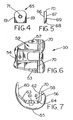
- FIGS. 4-7 depict an alternative modular embodiment of the invention.
- the use of a modular add-on allows a conventional implant to be adapted for four compartment articulation.
- the implant 50 includes arcuate medial 52 and lateral 53 condyles joined together at their anterior aspects to form a patellar flange 54.
- Each of the medial 52 and lateral 53 condyles is made up of a distal condyle 55 and a posterior condyle 56.
- the patellar flange 54, the distal condyles 55 and the posterior condyles 56 define a smooth articular surface extending around the exterior of the implant 50.
- the articular surface terminates at the apexes 58 of the posterior condyles 56.
- the terminal portion of the articular surface is defined by the radius R.
- the interior of the implant 1 is defined by a box 59.
- the box 59 includes an anterior box surface 60, a distal box surface 61 and a posterior box surface 62.
- the anterior 60 and distal 61 box surfaces are blended by an anterior chamfer surface 63.
- the distal 61 and posterior 62 box surfaces are blended by a posterior chamfer surface 64.
- FIGS. 4 and 5 depict an articular surface module 65.
- the module 65 includes a front surface 66, a back surface 67, a bottom surface 68, side surfaces 69, and a top surface 70.
- the back 67 and bottom 68 of the module 65 are shaped to seat against the posterior box surface 62 and posterior chamfer surface 64 respectively.
- the top surface 70 has an articular shape matching the articular surface of the implant 50 near the apexes 58.
- the top 70 of the module forms an extension of the articular surface, or a superior fourth compartment, as shown in FIGS. 6 and 7 .
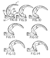
- This spine/cam interaction creates a center for rotation of the femoral component relative to the tibial component and prevents anterior subluxation of the femoral component relative to the tibial component.
- the distance from the spine/cam contact to the top of the spine is called the "jump height" and is a measure of the subluxation resistance of a particular spine/cam combination because the cam would have to jump over the spine for subluxation to occur.
- jump height is of increased concern.
- bending of the spine is a concern due to increased loads during activities such as squatting.
- the cam is located relatively low compared to the top of the distal condyles.
- the cam begins to ride up the spine and the jump height can be significantly shortened leading to an increased possibility of subluxation and an increased possibility of bending the spine because of the greater bending moment.
- a high cam placement is used similar to the design of the NexGen ® Complete Knee Solution manufactured and sold by Zimmer, Inc.
- the extreme flexion potential of the knee is enhanced. Extreme flexion is facilitated while maintaining a safe level of subluxation resistance.
- the jump height increases from 90 degrees, FIG. 8 , to approximately 130 degrees, FIG. 12 . Beyond 130 degrees, the cam rises only slightly, thus maintaining a large jump height even in deep flexion.
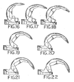
- FIG. 15 further enhances the jump height of the spine cam articulation.
- the exemplary cam in FIGS. 1 and 8-14 is cylindrical at its functional articulating surface. It is placed far superiorly between the superior posterior condyles to increase jump height in flexion.
- the cam in FIGS. 15-22 is made non-cylindrical, being made up of blended circles or other geometries.
- An exemplary non-cylindrical cam is shown in FIG. 15 .
- the cam 100 includes a relatively flat portion 101, a first spine contact portion 102 having a first radius defining a circle, and a second spine contact portion 104 having a second radius defining a circle.
- the first spine contact portion 102 is an arc of the circle defined by the first radius.
- the cam 100 alternatively includes a third spine contact portion 106, also shown in FIG. 15 , having a third radius defining a circle.
- the alternative third spine contact portion projects beyond the condyles in order to maintain the proper femoral position relative to the tibia in deep flexion.
- the radius of the third portion 106 when present, forms the posterior most cam surface and the end of the cam articular surface.
- One way to achieve the described relationships between the spine contacting portions is to increase the radius of the cam 100 posteriorly from the first spine contact portion 102 to the second spine contact portion 104.
- the third spine contacting portion 106 would be made smaller than the second spine contacting portion 104 and would articulate as shown in FIGS. 21 and 22 .
- Another way to achieve the inventive relationships is to offset the centers of the first and second radii in the anterior/posterior direction. Depending on the particular radius values and offset chosen, additional radii may be necessary to smoothly blend the first and second spine contacting surfaces.
Landscapes
- Health & Medical Sciences (AREA)
- Orthopedic Medicine & Surgery (AREA)
- Physical Education & Sports Medicine (AREA)
- Cardiology (AREA)
- Oral & Maxillofacial Surgery (AREA)
- Transplantation (AREA)
- Engineering & Computer Science (AREA)
- Biomedical Technology (AREA)
- Heart & Thoracic Surgery (AREA)
- Vascular Medicine (AREA)
- Life Sciences & Earth Sciences (AREA)
- Animal Behavior & Ethology (AREA)
- General Health & Medical Sciences (AREA)
- Public Health (AREA)
- Veterinary Medicine (AREA)
- Prostheses (AREA)
Description
- The present invention relates to knee prostheses for replacing the articular surfaces of a diseased or injured human knee. More particularly, the present invention relates to a knee prosthesis having an extended range of flexion.
- Disease and trauma affecting the articular surfaces of the knee joint are commonly effectively treated by surgically replacing the articulating ends of the femur and tibia with prosthetic femoral and tibial implants, referred to as total knee replacements (TKR). These implants are made of materials that exhibit a low coefficient of friction as they articulate against one another so as to restore normal, pain free, knee function. Modem TKR's are tricompartmental designs. That is, they replace three separate articulating surfaces within the knee joint; namely the patello-femoral joint and the lateral and medial inferior tibio-femoral joints. These implants are designed to articulate from a position of slight hyperextension to approximately 115 to 130 degrees of flexion. Such a tricompartmental design can meet the needs of most TKR patients even though the healthy human knee is capable of a range of motion (ROM) approaching 170 degrees. However, there are some TKR patients who have particular need to obtain very high flexion in their knee joint, usually as a result of cultural considerations. For many in the orient, and for some in the west, a TKR which permits a patient to achieve a ROM in excess of 150 degrees is desirable to allow deep kneeling, squatting, and sitting on the floor with the legs tucked underneath.
- In order to meet such a high flexion requirement, the present invention provides a fourth articulating compartment, namely the superior posterior femoral condyles. All prior TKR designs ignore the superior posterior condyles. The articulating surface of the posterior condyles of prior TKR's continue their natural curves until the posterior condylar surface meets the interior posterior wall of the TKR fixation surface. Where the two surfaces meet, an edge is formed. For simply aesthetic reasons, the posterior superior edge of standard TKR's may have a small fillet. If such a TKR is able to articulate beyond 130 degrees at all, then the edge directly articulates against the tibial articulating surface which is usually made of ultra high molecular weight polyethylene (UHMWPE). Such a condition is contraindicated as it will lead to extremely small contact areas between the articulating components and could lead to exceptionally high wear rates. Such a condition could ultimately lead to the destruction and failure of the TKR.
US Patent no. 5,609,645 (vinciguerva ) shows such a prior art prosthesis in which an edge is formed between the superior posterior femoral condyles and the shims fitted into the internal box of the prosthesis. In the present invention, provision is made to add an additional articulating surface to each of the superior posterior femoral condyles so that at very high flexion angles, a proper articulation is maintained. Articulation along the superior posterior condylar surface of the present invention is intended. Thus, the superior posterior condyles represent a fourth compartment of articulation. - The superior posterior articulating surface is achieved by first increasing the thickness of the superior posterior condylar portion of the TKR femoral component to widen the superior posterior edge of the posterior condyle. Second, the newly created surface at the superior posterior condyle is smoothly rounded to provide an articular surface with no sharp changes in the surface contours. In one embodiment, the fourth articular compartment of this invention is provided in a one piece femoral design. In another embodiment, it is provided as a modular addition to an existing prior art femoral component. In another embodiment, the fourth compartment is combined with a posterior stabilized (PS) TKR design that includes a tibial post and cooperating femoral cam characterized by low engagement of the cam on the spine.
-
-
FIG. 1 is a side plan view of a femoral knee implant according to the present invention. -
FIG. 2 is a side plan view of an alternative embodiment of the femoral knee implant according to the present invention. -
FIG. 3 is a side plan view of an alternative embodiment of the femoral knee implant according to the present invention. -
FIG. 4 is a front plan view of an articular surface module according to the present invention. -
FIG. 5 is a side plan view of the articular module ofFIG. 4 . -
FIG. 6 is a top plan view of the articular surface module ofFIG. 4 shown mounted on a femoral knee implant. -
FIG. 7 is a side plan view of the articular surface module ofFIG. 4 shown mounted on a femoral knee implant. -
FIGS. 8-14 are side plan views of the femoral knee implant ofFIG. 1 articulating with a tibial component of the present invention between 90 degrees and 160 degrees of flexion. -
FIG. 15 is a side view of an alternative embodiment of the femoral knee implant according to the present invention. -
FIGS. 16-22 are side plan views of the femoral knee implant ofFIG. 15 articulating with a tibial component of the present invention between 90 degrees and 160 degrees of flexion. -
FIGS. 1,2,3 ,7 and15 show embodiments of the femoral knee component of the present invention oriented at zero degrees of flexion. Unless otherwise noted, the geometric relationships of this invention are descriptive of a femoral knee implant in this orientation. -
FIG. 1 depicts an exemplary one-piece femoral knee implant 1 according to the present invention. The implant 1 includes arcuate medial 2 and lateral (not shown) condyles joined together at their anterior aspects to form apatellar flange 4. Each of the medial 2 and lateral condyles includes a distal condyle 5, a posterior condyle 6, and a superior condyle 7. Thepatellar flange 4, the distal condyles 5, the posterior condyles 6, and the superior condyles 7 define a smooth articular surface extending around the exterior of the implant 1. The interior of the implant 1 is defined by a box 9. The box 9 includes an anterior box surface 10, a distal box surface 11 and a posterior box surface 12. The anterior 10 and the distal 11 box surfaces are blended by ananterior chamfer surface 13. The distal 11 and posterior 12 box surfaces are blended by aposterior chamfer surface 14. The four compartment knee of the present invention accommodates flexion in the range of 165 degrees. - In order to provide the superior condyles 7 of the present invention, the superior aspect of the posterior condyles 6 is extended toward the
anterior flange 4 to allow the articular surface to extend further around and back anteriorly than with prior femoral implants. Extending the superior aspect of the posterior condyle can be done in several ways. As shown inFIG. 1 , the entire posterior condyle is thickened such that the posterior box surface 12 is further from the posterior condyle 6 exterior surface and nearer the anterior box surface 10. This widens the superior aspect of the posterior condyle so that the articular surface can be extended to form the superior condyle 7. Alternatively, posterior condyle 6 can be shortened by removing material from the superior aspect where the condyle begins to taper which will have the effect of leaving a thicker superior aspect that can be shaped into a superior condyle. Yet another alternative is to change the angle that the posterior box surface 12 makes with the distal box surface 11. By making the included angle between these two surface smaller, the superior aspect of the posterior condyle is made wider to provide for a superior condyle 7. - Taking this angle change further leads to the embodiment of
FIG. 2 . Here, the angle between theposterior box surface 16 and thedistal box surface 18 has been made less than 90 degrees to provide ample width for asuperior condyle 20. Thedashed line 22 depicts the angle of the posterior box surface of a typical prior art femoral component. In order for the femoral component to be easily implantable,posterior box surfaces 16 and theanterior box surface 24 must be parallel or slightly diverging toward the box opening. Therefore it may be necessary, as shown inFIG. 2 , where the posterior box surface has been angled inwardly, to angle theanterior box surface 24 outwardly. Thedashed line 26 depicts the angle of the anterior box surface of a typical prior art femoral component. -
FIG. 3 illustrates another alternative embodiment for moving the superior aspect of theposterior condyle 28 anteriorly. In this embodiment, the entire box; including theposterior surface 30,distal surface 32,anterior surface 34 andchamfers posterior condyle 28 anteriorly and slightly superiorly. Asuperior condyle 42 can then be formed at the superior aspect of theposterior condyle 28. The dashedlines 44 depict the box and articular surfaces of a typical prior art femoral component before the box is rotated. - In prior art implants the distal box surface 27 (dashed) is parallel to the tangent 31 of the distal condyles at their most prominent point. This helps a surgeon orient the femoral component at full extension. In the embodiment of
FIG. 3 , the box is rotated so that thedistal surface 32 is angled relative to the tangent 31. -
FIGS. 4-7 depict an alternative modular embodiment of the invention. The use of a modular add-on allows a conventional implant to be adapted for four compartment articulation. Theimplant 50 includesarcuate medial 52 and lateral 53 condyles joined together at their anterior aspects to form apatellar flange 54. Each of the medial 52 and lateral 53 condyles is made up of adistal condyle 55 and aposterior condyle 56. Thepatellar flange 54, thedistal condyles 55 and theposterior condyles 56 define a smooth articular surface extending around the exterior of theimplant 50. The articular surface terminates at theapexes 58 of theposterior condyles 56. The terminal portion of the articular surface is defined by the radius R. The interior of the implant 1 is defined by abox 59. Thebox 59 includes ananterior box surface 60, adistal box surface 61 and aposterior box surface 62. The anterior 60 and distal 61 box surfaces are blended by ananterior chamfer surface 63. The distal 61 andposterior 62 box surfaces are blended by aposterior chamfer surface 64. -
FIGS. 4 and 5 depict anarticular surface module 65. Themodule 65 includes afront surface 66, aback surface 67, abottom surface 68, side surfaces 69, and atop surface 70. The back 67 and bottom 68 of themodule 65 are shaped to seat against theposterior box surface 62 andposterior chamfer surface 64 respectively. Thetop surface 70 has an articular shape matching the articular surface of theimplant 50 near theapexes 58. When the back 67 and bottom 68 of themodule 65 are seated in theimplant box 59, the top 70 of the module forms an extension of the articular surface, or a superior fourth compartment, as shown inFIGS. 6 and 7 . The extended articular surface blends functionally with the articular surface to allow additional articulation of the femur relative to the tibia. Thus, a smooth transition is provided from articulation on the implant to articulation on the module. In the embodiment shown inFIG. 7 , themodule 65 extends the radius R. A module is used similarly on both the medial and lateral posterior condyles. A throughhole 71 in themodule 65 and corresponding threaded holes in the posterior condyles allow themodule 65 to be securely attached to theimplant 50. Other well known means of attachment may also be used such as cement or clips. - The femoral component of the present invention accommodates deep flexion through the use of a fourth articular region. Other femoral features help to maximize the potential of this improved articular surface design.
FIGS. 8-14 illustrate the femoral component 1 ofFIG. 1 articulating with atibial component 80. Thetibial component 80 includes aspine 82 having anarticular surface 84. The femoral component 1 includes acam 90 having anarticular surface 92. In flexion, the camarticular surface 92 bears on the spinearticular surface 84. This spine/cam interaction creates a center for rotation of the femoral component relative to the tibial component and prevents anterior subluxation of the femoral component relative to the tibial component. The distance from the spine/cam contact to the top of the spine is called the "jump height" and is a measure of the subluxation resistance of a particular spine/cam combination because the cam would have to jump over the spine for subluxation to occur. In extreme flexion, such as that for which the present invention is designed, jump height is of increased concern. Likewise, bending of the spine is a concern due to increased loads during activities such as squatting. In many prior art implant designs, the cam is located relatively low compared to the top of the distal condyles. If these prior art knees are flexed deeply, the cam begins to ride up the spine and the jump height can be significantly shortened leading to an increased possibility of subluxation and an increased possibility of bending the spine because of the greater bending moment. In the present invention a high cam placement is used similar to the design of the NexGen® Complete Knee Solution manufactured and sold by Zimmer, Inc. By combining high cam placement with a fourth articular compartment, the extreme flexion potential of the knee is enhanced. Extreme flexion is facilitated while maintaining a safe level of subluxation resistance. As shown inFIGS. 8-14 , the jump height increases from 90 degrees,FIG. 8 , to approximately 130 degrees,FIG. 12 . Beyond 130 degrees, the cam rises only slightly, thus maintaining a large jump height even in deep flexion. - The embodiment of
FIG. 15 further enhances the jump height of the spine cam articulation. The exemplary cam inFIGS. 1 and8-14 is cylindrical at its functional articulating surface. It is placed far superiorly between the superior posterior condyles to increase jump height in flexion. To further enhance jump height, the cam inFIGS. 15-22 is made non-cylindrical, being made up of blended circles or other geometries. An exemplary non-cylindrical cam is shown inFIG. 15 . Thecam 100 includes a relatively flat portion 101, a firstspine contact portion 102 having a first radius defining a circle, and a secondspine contact portion 104 having a second radius defining a circle. The firstspine contact portion 102 is an arc of the circle defined by the first radius. The secondspine contact portion 104 is an arc of the circle defined by the second radius. The second spine contact portion extends further posteriorly than the perimeter of the circle defined by the first radius. In the embodiment shown inFIG. 15 , the first and second spine contact portions form an ovoidarticular surface cam 100 causes it to reach downwardly and contact the spine lower at higher angles of flexion as shown inFIGS. 16-20 . Thesecond contact portion 104 causes the femur to roll back in deep flexion to prevent the femoral bone, where it exits the posterior box, from impinging on the tibial articular surface. The top 108 of thecam 100 completes the cam profile. - The
cam 100 alternatively includes a thirdspine contact portion 106, also shown inFIG. 15 , having a third radius defining a circle. The alternative third spine contact portion projects beyond the condyles in order to maintain the proper femoral position relative to the tibia in deep flexion. The radius of thethird portion 106, when present, forms the posterior most cam surface and the end of the cam articular surface. - One way to achieve the described relationships between the spine contacting portions is to increase the radius of the
cam 100 posteriorly from the firstspine contact portion 102 to the secondspine contact portion 104. The thirdspine contacting portion 106 would be made smaller than the secondspine contacting portion 104 and would articulate as shown inFIGS. 21 and 22 . Another way to achieve the inventive relationships is to offset the centers of the first and second radii in the anterior/posterior direction. Depending on the particular radius values and offset chosen, additional radii may be necessary to smoothly blend the first and second spine contacting surfaces. - It will be understood by those skilled in the art that the foregoing has described a preferred embodiment of the present invention and that variations in design and construction may be made to the preferred embodiment without departing from the spirit and scope of the invention defined by the appended claims.
- The invention will be further described by the following paragraphs in Annex A.
- 1. A prosthetic knee implant including:
- a tibial component comprising a tibial articular surface; and
- a femoral component (1) comprising arcuate medial (2) and lateral condyles joined together to form a patellar flange (4), each of the medial (2) and lateral condyles including a distal condyle (5), a posterior condyle (6), and a superior condyle (7), characterised in that the superior aspects (7) of the posterior condyles (6) are extended toward the anterior flange (4) and the superior condyles (7) are formed on the superior aspect such that the patellar flange (4), the distal condyles (5), the posterior condyles (6), and the superior condyles (7) define a smooth articular surface extending around the exterior of the implant (1) for articulation with the tibial articular surface, the superior condyles (7) extending the articular surface back toward the patellar flange (4) to accommodate flexion of the femoral component (1) relative to the tibial component of at least 160 degrees.
- 2. The knee implant of paragraph 1 characterised in that the femoral component (1) further includes a hollow interior bordered by an anterior box surface opposite the patellar flange (4), distal box surfaces (18) opposite the distal condyles (5), and posterior box surfaces (16) opposite the posterior condyles (6), the anterior (24) and distal (18) box surfaces being joined by an anterior chamfer box surface, the distal (18) and posterior (16) box surfaces being joined by a posterior chamfer box surface, the included angle between the distal (18) and posterior (16) box surfaces being less than 90 degrees.
- 3. The knee implant of paragraph 1 characterised in that the femoral component (1) further includes a hollow interior bordered by an anterior box surface (34) opposite the patellar flange, distal box surfaces (32) opposite the distal condyles, and posterior box surfaces (30) opposite the posterior condyles (28), the anterior (34) and distal (32) box surfaces being joined by an anterior chamfer box surface (36), the distal (32) and posterior (30) box surfaces being joined by a posterior chamfer box surface (38), the distal condyles (27) having a tangent (31) at their most prominent distal point, the distal box surface (32) diverging posteriorly away from the tangent (31).
- 4. The knee implant of paragraph 1 characterised in that the tibial component (80) includes a spine (82) extending from the tibial articular surface, the spine (82) having a top surface furthest from the tibial articular surface and an articular surface (84), and the femoral component (1) includes a cam (90) between the superior posterior condyles (7), the cam (90) having an articular surface (92), the cam articular surface (92) contacting the spine articular surface (84) at varying vertical locations as the femoral (1) and tibial (80) components are flexed relative to one another beyond 90 degrees, the distance from the contact between the cam (90) and spine (84) articular surfaces to the spine top surface being greater at 130 degrees than at 90 degrees.
- 5. The knee implant of
paragraph 4 characterised in that the distance from the contact between the cam (92) and spine (84) articular surfaces to the spine top surface is approximately the same for angles of flexion from 130 to 160 degrees of flexion. - 6. The knee implant of paragraph 1 characterised in that the tibial component (80) includes a spine (82) extending from the tibial articular surface, the spine (82) having a top surface furthest from the tibial articular surface (84), the femoral component (1) includes a cam (100) between the superior posterior condyles, the cam (100) has a non-cylindrical articular surface with a first spine contacting portion (102) and a second spine contacting portion (104) located further posteriorly than the first spine contacting portion (102).
- 7. The knee implant of paragraph 5 characterised in that the first spine contacting portion (102) has a first radius defining a first circle and the second spine contacting portion (104) has a second radius defining a second circle, the first spine contacting portion (102) being an arc of the first circle and the second spine contacting portion (104) being an arc of the second circle, the second spine contact portion (104) extending further posteriorly than the perimeter of the first circle.
- 8. The knee implant of paragraph 6 characterised in that the cam articular surface has a curved surface whose radius increases from the first contact portion (102) to the second contact portion (104).
- 9. The knee implant of paragraph 6 characterised in that the first spine contact portion (102) has a radius and the second spine contact portion (104) has a radius, the radius of the second spine contact portion (104) being larger than the radius of the first spine contact portion (102).
- 10. The knee implant of paragraph 9 characterised in that the cam (100) has a third spine contacting portion (106) located further posteriorly than the second spine contacting portion (104) and having a third radius, the third radius being smaller than the second radius.
- 11. The knee implant of paragraph 10 characterised in that the third spine contacting portion (106) extends posteriorly further than the posterior condyles.
Claims (2)
- A femoral knee implant (50) for articulation with a tibial surface, the femoral knee implant (50) comprising:an articular surface for articulation with the tibial surface;a box (59) defining the interior surfaces of the implant (50); anda module (65) comprising a back surface (67) and a top surface (70), the back surface (67) being shaped to seat against a portion of the box (59), the top surface (70) being shaped to form an extension of the articular surface, the top surface (70) blending functionally with the articular surface to allow further articulation of the femoral implant (50) on the tibial surface when the back surface (67) is seated on a portion of the box (59).
- The femoral knee implant (50) of claim 1 further comprising arcuate medial (52) and lateral (53) condyles joined together to form a patellar flange (54), each of the medial (52) and lateral (53) condyles including a distal condyle (55) and a posterior condyle (56), the patellar flange(54), the distal condyles (55) and the posterior condyles (56) defining the articular surface extending around the exterior of the implant (50), each posterior condyle (56) including an apex (58) at its highest point, the articular surface terminating at the apexes (58) of the posterior condyles (56), the articular surface being defined by a radius R near the apexes (58), the top surface (70) blending with the radius R to form a functionally smooth continuation of the articular surface.
Applications Claiming Priority (3)
| Application Number | Priority Date | Filing Date | Title |
|---|---|---|---|
| US09/037,417 US6123729A (en) | 1998-03-10 | 1998-03-10 | Four compartment knee |
| US37417 | 1998-03-10 | ||
| EP99200699A EP0941719B1 (en) | 1998-03-10 | 1999-03-09 | Four compartment knee |
Related Parent Applications (2)
| Application Number | Title | Priority Date | Filing Date |
|---|---|---|---|
| EP99200699.9 Division | 1999-03-09 | ||
| EP99200699A Division EP0941719B1 (en) | 1998-03-10 | 1999-03-09 | Four compartment knee |
Publications (3)
| Publication Number | Publication Date |
|---|---|
| EP1518521A2 EP1518521A2 (en) | 2005-03-30 |
| EP1518521A3 EP1518521A3 (en) | 2005-10-12 |
| EP1518521B1 true EP1518521B1 (en) | 2010-06-30 |
Family
ID=21894222
Family Applications (2)
| Application Number | Title | Priority Date | Filing Date |
|---|---|---|---|
| EP99200699A Expired - Lifetime EP0941719B1 (en) | 1998-03-10 | 1999-03-09 | Four compartment knee |
| EP04030369A Expired - Lifetime EP1518521B1 (en) | 1998-03-10 | 1999-03-09 | Four compartment knee |
Family Applications Before (1)
| Application Number | Title | Priority Date | Filing Date |
|---|---|---|---|
| EP99200699A Expired - Lifetime EP0941719B1 (en) | 1998-03-10 | 1999-03-09 | Four compartment knee |
Country Status (7)
| Country | Link |
|---|---|
| US (2) | US6123729A (en) |
| EP (2) | EP0941719B1 (en) |
| JP (1) | JP4290803B2 (en) |
| AU (1) | AU737463B2 (en) |
| CA (2) | CA2263086C (en) |
| DE (2) | DE69922723T2 (en) |
| ES (2) | ES2234202T3 (en) |
Families Citing this family (123)
| Publication number | Priority date | Publication date | Assignee | Title |
|---|---|---|---|---|
| US8603095B2 (en) | 1994-09-02 | 2013-12-10 | Puget Bio Ventures LLC | Apparatuses for femoral and tibial resection |
| US6695848B2 (en) | 1994-09-02 | 2004-02-24 | Hudson Surgical Design, Inc. | Methods for femoral and tibial resection |
| US8617242B2 (en) | 2001-05-25 | 2013-12-31 | Conformis, Inc. | Implant device and method for manufacture |
| US8882847B2 (en) | 2001-05-25 | 2014-11-11 | Conformis, Inc. | Patient selectable knee joint arthroplasty devices |
| US8545569B2 (en) | 2001-05-25 | 2013-10-01 | Conformis, Inc. | Patient selectable knee arthroplasty devices |
| US8556983B2 (en) | 2001-05-25 | 2013-10-15 | Conformis, Inc. | Patient-adapted and improved orthopedic implants, designs and related tools |
| US9603711B2 (en) | 2001-05-25 | 2017-03-28 | Conformis, Inc. | Patient-adapted and improved articular implants, designs and related guide tools |
| US8480754B2 (en) | 2001-05-25 | 2013-07-09 | Conformis, Inc. | Patient-adapted and improved articular implants, designs and related guide tools |
| WO2000035346A2 (en) | 1998-09-14 | 2000-06-22 | Stanford University | Assessing the condition of a joint and preventing damage |
| US6443991B1 (en) | 1998-09-21 | 2002-09-03 | Depuy Orthopaedics, Inc. | Posterior stabilized mobile bearing knee |
| US6413279B1 (en) | 1999-03-01 | 2002-07-02 | Biomet, Inc. | Floating bearing knee joint prosthesis with a fixed tibial post |
| US6972039B2 (en) | 1999-03-01 | 2005-12-06 | Biomet, Inc. | Floating bearing knee joint prosthesis with a fixed tibial post |
| DE29906909U1 (en) * | 1999-03-02 | 1999-09-30 | Plus Endoprothetik Ag, Rotkreuz | Femur sledge |
| US6558426B1 (en) | 2000-11-28 | 2003-05-06 | Medidea, Llc | Multiple-cam, posterior-stabilized knee prosthesis |
| US8062377B2 (en) | 2001-03-05 | 2011-11-22 | Hudson Surgical Design, Inc. | Methods and apparatus for knee arthroplasty |
| US7776085B2 (en) | 2001-05-01 | 2010-08-17 | Amedica Corporation | Knee prosthesis with ceramic tibial component |
| US7695521B2 (en) | 2001-05-01 | 2010-04-13 | Amedica Corporation | Hip prosthesis with monoblock ceramic acetabular cup |
| US6482209B1 (en) | 2001-06-14 | 2002-11-19 | Gerard A. Engh | Apparatus and method for sculpting the surface of a joint |
| AU2002324443A1 (en) | 2001-06-14 | 2003-01-02 | Amedica Corporation | Metal-ceramic composite articulation |
| US6821470B2 (en) * | 2001-06-29 | 2004-11-23 | Depuy Products, Inc. | Joint prosthesis molding method |
| US20030009230A1 (en) * | 2001-06-30 | 2003-01-09 | Gundlapalli Rama Rao V. | Surface sterilizable joint replacement prosthesis component with insert |
| US6695619B2 (en) * | 2001-08-09 | 2004-02-24 | Oliver Brown-Wilkinson | Orthopaedic demonstration aid |
| FR2835738B1 (en) * | 2002-02-14 | 2004-10-01 | Jacques Afriat | TOTAL KNEE PROSTHESIS |
| CA2646389A1 (en) * | 2002-02-20 | 2003-08-28 | Donald M. Smucker | Knee arthroplasty prosthesis and method |
| US20090311795A1 (en) * | 2002-03-21 | 2009-12-17 | Hinz Martin C | Bilateral control of functions traditionally regulated by only serotonin or only dopamine |
| US20070293571A1 (en) * | 2006-06-08 | 2007-12-20 | Hinz Martin C | Adminstration of dopa precursors with sources of dopa to effectuate optimal catecholamine neurotransmitter outcomes |
| US7150761B2 (en) * | 2002-05-24 | 2006-12-19 | Medicinelodge, Inc. | Modular femoral components for knee arthroplasty |
| US7615081B2 (en) * | 2002-05-24 | 2009-11-10 | Zimmer, Inc. | Femoral components for knee arthroplasty |
| US20040054416A1 (en) | 2002-09-12 | 2004-03-18 | Joe Wyss | Posterior stabilized knee with varus-valgus constraint |
| FR2844704B1 (en) * | 2002-09-24 | 2005-06-03 | Biomet Merck France | KNEE PROSTHESIS WITH MOBILE TRAY |
| AU2003287190A1 (en) | 2002-10-23 | 2004-05-13 | Alastair J. T. Clemow | Modular femoral component for a total knee joint replacement for minimally invasive implantation |
| CA2505371A1 (en) | 2002-11-07 | 2004-05-27 | Conformis, Inc. | Methods for determining meniscal size and shape and for devising treatment |
| US6770099B2 (en) * | 2002-11-19 | 2004-08-03 | Zimmer Technology, Inc. | Femoral prosthesis |
| US20040102852A1 (en) | 2002-11-22 | 2004-05-27 | Johnson Erin M. | Modular knee prosthesis |
| US6749638B1 (en) * | 2002-11-22 | 2004-06-15 | Zimmer Technology, Inc. | Modular knee prosthesis |
| WO2004058098A2 (en) * | 2002-12-17 | 2004-07-15 | Amedica Corporation | Total disc implant |
| ES2465090T3 (en) | 2002-12-20 | 2014-06-05 | Smith & Nephew, Inc. | High performance knee prostheses |
| WO2004069104A1 (en) | 2003-02-08 | 2004-08-19 | Depuy International Limited | A knee joint prosthesis |
| FR2855963B1 (en) * | 2003-06-13 | 2005-11-18 | X Nov | FEMORAL PROSTHESIS WITH PROTECTOR |
| US20050143832A1 (en) * | 2003-10-17 | 2005-06-30 | Carson Christopher P. | High flexion articular insert |
| US8535383B2 (en) * | 2004-01-12 | 2013-09-17 | DePuy Synthes Products, LLC | Systems and methods for compartmental replacement in a knee |
| EP1703867B1 (en) * | 2004-01-12 | 2012-03-07 | Depuy Products, Inc. | Systems for compartmental replacement in a knee |
| US7544209B2 (en) | 2004-01-12 | 2009-06-09 | Lotke Paul A | Patello-femoral prosthesis |
| US8002840B2 (en) | 2004-01-12 | 2011-08-23 | Depuy Products, Inc. | Systems and methods for compartmental replacement in a knee |
| US8114083B2 (en) | 2004-01-14 | 2012-02-14 | Hudson Surgical Design, Inc. | Methods and apparatus for improved drilling and milling tools for resection |
| US20060030854A1 (en) | 2004-02-02 | 2006-02-09 | Haines Timothy G | Methods and apparatus for wireplasty bone resection |
| US8021368B2 (en) | 2004-01-14 | 2011-09-20 | Hudson Surgical Design, Inc. | Methods and apparatus for improved cutting tools for resection |
| US20060030855A1 (en) | 2004-03-08 | 2006-02-09 | Haines Timothy G | Methods and apparatus for improved profile based resection |
| JP3915989B2 (en) | 2004-03-17 | 2007-05-16 | 徹 勝呂 | Artificial knee joint |
| US20090036993A1 (en) * | 2004-04-22 | 2009-02-05 | Robert Metzger | Patellar implant |
| US7731755B2 (en) * | 2004-06-11 | 2010-06-08 | Depuy Products, Inc. | Posterior stabilized mobile bearing knee |
| US8852195B2 (en) | 2004-07-09 | 2014-10-07 | Zimmer, Inc. | Guide templates for surgical implants and related methods |
| US20070100461A1 (en) * | 2005-04-12 | 2007-05-03 | The University Of Vermont And State Agriculture College | Knee prosthesis |
| GB0510193D0 (en) * | 2005-05-19 | 2005-06-22 | Mcminn Derek J W | Knee prosthesis |
| WO2007007841A1 (en) * | 2005-07-14 | 2007-01-18 | Saga University | Artificial knee joint |
| US20070135921A1 (en) * | 2005-12-09 | 2007-06-14 | Park Kee B | Surgical implant |
| US8211181B2 (en) * | 2005-12-14 | 2012-07-03 | New York University | Surface guided knee replacement |
| US8292964B2 (en) * | 2005-12-14 | 2012-10-23 | New York University | Surface guided knee replacement |
| US8070821B2 (en) * | 2005-12-27 | 2011-12-06 | Howmedica Osteonics Corp. | Hybrid femoral implant |
| US20070179609A1 (en) * | 2006-01-27 | 2007-08-02 | Medicinelodge, Inc. | Therapeutic agent eluding implant with percutaneous supply |
| WO2007108804A1 (en) | 2006-03-21 | 2007-09-27 | Komistek Richard D | Moment induced total arthroplasty prosthetic |
| US20070225819A1 (en) * | 2006-03-24 | 2007-09-27 | Depuy Products, Inc. | Apparatus and method for the treatment of periprosthetic fractures |
| JP5266215B2 (en) | 2006-06-30 | 2013-08-21 | スミス アンド ネフュー インコーポレーテッド | Hinge prosthesis with anatomical movement |
| DE102006042829A1 (en) * | 2006-09-08 | 2008-03-27 | Siebel, Thomas, Dr. | knee prosthesis |
| US9107769B2 (en) | 2007-08-27 | 2015-08-18 | Kent M. Samuelson | Systems and methods for providing a femoral component |
| US9872774B2 (en) | 2007-08-27 | 2018-01-23 | Connor E. Samuelson | Systems and methods for providing a femoral component having a modular stem |
| US8366783B2 (en) | 2007-08-27 | 2013-02-05 | Samuelson Kent M | Systems and methods for providing deeper knee flexion capabilities for knee prosthesis patients |
| US8382846B2 (en) | 2007-08-27 | 2013-02-26 | Kent M. Samuelson | Systems and methods for providing deeper knee flexion capabilities for knee prosthesis patients |
| US10213826B2 (en) | 2007-08-27 | 2019-02-26 | Connor E Samuelson | Systems and methods for providing prosthetic components |
| US8273133B2 (en) * | 2007-08-27 | 2012-09-25 | Samuelson Kent M | Systems and methods for providing deeper knee flexion capabilities for knee prosthesis patients |
| US8292965B2 (en) * | 2008-02-11 | 2012-10-23 | New York University | Knee joint with a ramp |
| AU2009215530A1 (en) * | 2008-02-18 | 2009-08-27 | Maxx Orthopedics, Inc. | Total knee replacement prosthesis |
| WO2009111626A2 (en) | 2008-03-05 | 2009-09-11 | Conformis, Inc. | Implants for altering wear patterns of articular surfaces |
| WO2009140294A1 (en) | 2008-05-12 | 2009-11-19 | Conformis, Inc. | Devices and methods for treatment of facet and other joints |
| EP2323594B1 (en) * | 2008-06-24 | 2016-04-06 | Peter Stanley Walker | Recess-ramp knee joint prosthesis |
| US8236061B2 (en) | 2008-06-30 | 2012-08-07 | Depuy Products, Inc. | Orthopaedic knee prosthesis having controlled condylar curvature |
| US8192498B2 (en) | 2008-06-30 | 2012-06-05 | Depuy Products, Inc. | Posterior cructiate-retaining orthopaedic knee prosthesis having controlled condylar curvature |
| US9119723B2 (en) | 2008-06-30 | 2015-09-01 | Depuy (Ireland) | Posterior stabilized orthopaedic prosthesis assembly |
| US8206451B2 (en) | 2008-06-30 | 2012-06-26 | Depuy Products, Inc. | Posterior stabilized orthopaedic prosthesis |
| US9168145B2 (en) | 2008-06-30 | 2015-10-27 | Depuy (Ireland) | Posterior stabilized orthopaedic knee prosthesis having controlled condylar curvature |
| US8828086B2 (en) | 2008-06-30 | 2014-09-09 | Depuy (Ireland) | Orthopaedic femoral component having controlled condylar curvature |
| AU2015203508B2 (en) * | 2008-06-30 | 2017-08-17 | Depuy Products, Inc. | Orthopaedic knee prosthesis having controlled condylar curvature |
| US8187335B2 (en) | 2008-06-30 | 2012-05-29 | Depuy Products, Inc. | Posterior stabilized orthopaedic knee prosthesis having controlled condylar curvature |
| US8202323B2 (en) * | 2008-07-16 | 2012-06-19 | Depuy Products, Inc. | Knee prostheses with enhanced kinematics |
| US8715358B2 (en) * | 2008-07-18 | 2014-05-06 | Michael A. Masini | PCL retaining ACL substituting TKA apparatus and method |
| US20100161067A1 (en) * | 2008-12-23 | 2010-06-24 | Aesculap Ag | Knee prosthesis |
| US8491662B2 (en) | 2008-12-23 | 2013-07-23 | Aesculap Ag | Knee prosthesis |
| US9220600B2 (en) | 2008-12-23 | 2015-12-29 | Aesculap Implant Systems, Llc | Knee prosthesis |
| WO2010099231A2 (en) | 2009-02-24 | 2010-09-02 | Conformis, Inc. | Automated systems for manufacturing patient-specific orthopedic implants and instrumentation |
| CA2756226C (en) * | 2009-03-27 | 2017-01-24 | Smith & Nephew Orthopaedics Ag | Artificial knee joint |
| US8915965B2 (en) | 2009-05-07 | 2014-12-23 | Depuy (Ireland) | Anterior stabilized knee implant |
| EP2272466A1 (en) | 2009-07-10 | 2011-01-12 | Medizinische Hochschule Hannover | Knee joint prosthesis and method for producing said prosthesis |
| AU2010327987B2 (en) | 2009-12-11 | 2015-04-02 | Conformis, Inc. | Patient-specific and patient-engineered orthopedic implants |
| US8308808B2 (en) | 2010-02-19 | 2012-11-13 | Biomet Manufacturing Corp. | Latent mobile bearing for prosthetic device |
| CN103118636B (en) | 2010-07-24 | 2016-08-17 | 捷迈有限公司 | Asymmetric tibial component for knee prosthesis |
| US8764840B2 (en) | 2010-07-24 | 2014-07-01 | Zimmer, Inc. | Tibial prosthesis |
| CN103402462B (en) | 2010-08-12 | 2016-09-07 | 史密夫和内修有限公司 | For the structure that orthopaedic implants is fixing |
| EP2613739B1 (en) | 2010-09-10 | 2017-06-07 | Zimmer, Inc. | Motion facilitating tibial components for a knee prosthesis |
| US8317870B2 (en) | 2010-09-30 | 2012-11-27 | Depuy Products, Inc. | Tibial component of a knee prosthesis having an angled cement pocket |
| US8603101B2 (en) | 2010-12-17 | 2013-12-10 | Zimmer, Inc. | Provisional tibial prosthesis system |
| US8403994B2 (en) | 2011-01-19 | 2013-03-26 | Wright Medical Technology, Inc. | Knee implant system |
| WO2012112698A2 (en) | 2011-02-15 | 2012-08-23 | Conformis, Inc. | Patient-adapted and improved articular implants, procedures and tools to address, assess, correct, modify and/or accommodate anatomical variation and/or asymmetry |
| US8747479B2 (en) | 2011-04-26 | 2014-06-10 | Michael A. McShane | Tibial component |
| JP6029817B2 (en) | 2011-09-27 | 2016-11-24 | 京セラメディカル株式会社 | Total knee implant |
| AU2012227339B2 (en) * | 2011-09-30 | 2015-07-02 | Depuy Products, Inc. | Tibial component of a knee prosthesis having an angled cement pocket |
| US8690954B2 (en) * | 2011-11-18 | 2014-04-08 | Zimmer, Inc. | Tibial bearing component for a knee prosthesis with improved articular characteristics |
| WO2013077919A1 (en) | 2011-11-21 | 2013-05-30 | Zimmer, Inc. | Tibial baseplate with asymmetric placement of fixation structures |
| CN103126787B (en) * | 2011-11-28 | 2015-03-04 | 北京纳通科技集团有限公司 | Knee-joint prosthesis |
| ES2869958T3 (en) | 2012-01-30 | 2021-10-26 | Zimmer Inc | Asymmetric tibial components for a knee replacement |
| RS61560B1 (en) * | 2013-06-23 | 2021-04-29 | Canary Medical Inc | Devices, systems and methods for monitoring knee replacements |
| US9925052B2 (en) | 2013-08-30 | 2018-03-27 | Zimmer, Inc. | Method for optimizing implant designs |
| ITMI20132154A1 (en) * | 2013-12-20 | 2015-06-21 | Adler Ortho S R L | FEMORAL COMPONENT FOR KNEE PROSTHESIS. |
| AU2015213574B2 (en) | 2014-02-10 | 2019-08-01 | Limacorporate S.P.A. | Artificial knee joint |
| JP6470541B2 (en) * | 2014-10-21 | 2019-02-13 | 京セラ株式会社 | Total knee implant |
| EP3352708B1 (en) | 2015-09-21 | 2020-07-22 | Zimmer, Inc. | Prosthesis system including tibial bearing component |
| US10179052B2 (en) | 2016-07-28 | 2019-01-15 | Depuy Ireland Unlimited Company | Total knee implant prosthesis assembly and method |
| CN106580524B (en) * | 2016-12-12 | 2018-08-07 | 上海昕健医疗技术有限公司 | Posterior stabilized knee prosthesis |
| FR3060970B1 (en) * | 2016-12-26 | 2019-02-01 | X Nov Ip | FEMALE PART OF A KNEE PROSTHESIS |
| ES3025978T3 (en) | 2017-03-10 | 2025-06-10 | Zimmer Inc | Tibial prosthesis with tibial bearing component securing feature |
| AU2018266322B2 (en) | 2017-05-12 | 2020-03-19 | Zimmer, Inc. | Femoral prostheses with upsizing and downsizing capabilities |
| US11426282B2 (en) | 2017-11-16 | 2022-08-30 | Zimmer, Inc. | Implants for adding joint inclination to a knee arthroplasty |
| US10307255B1 (en) | 2017-11-29 | 2019-06-04 | b-ONE Ortho, Corp. | Acetabular cup assembly |
| US10835380B2 (en) | 2018-04-30 | 2020-11-17 | Zimmer, Inc. | Posterior stabilized prosthesis system |
Family Cites Families (46)
| Publication number | Priority date | Publication date | Assignee | Title |
|---|---|---|---|---|
| GB1445684A (en) * | 1972-10-19 | 1976-08-11 | Nat Res Dev | Endoprosthetic bone joint devices |
| GB1507309A (en) * | 1974-10-14 | 1978-04-12 | Atomic Energy Authority Uk | Prosthetic knee joints |
| US4209861A (en) * | 1978-02-22 | 1980-07-01 | Howmedica, Inc. | Joint prosthesis |
| US4213209A (en) * | 1978-05-22 | 1980-07-22 | New York Society For The Relief Of The Ruptured And Crippled | Knee joint prosthesis |
| US4224697A (en) * | 1978-09-08 | 1980-09-30 | Hexcel Corporation | Constrained prosthetic knee |
| CH632151A5 (en) * | 1978-10-06 | 1982-09-30 | Sulzer Ag | ENDOPROTHESIS FOR A KNEE JOINT. |
| US4298992A (en) * | 1980-01-21 | 1981-11-10 | New York Society For The Relief Of The Ruptured And Crippled | Posteriorly stabilized total knee joint prosthesis |
| US4353136A (en) * | 1980-11-05 | 1982-10-12 | Polyzoides Apostolos J | Endoprosthetic knee joint |
| EP0103697A1 (en) * | 1982-09-22 | 1984-03-28 | GebràDer Sulzer Aktiengesellschaft | Knee joint prosthesis |
| JPS6077752A (en) * | 1983-09-30 | 1985-05-02 | 東海林 宏 | Meniscal artificial knee joint |
| US4634444A (en) * | 1984-02-09 | 1987-01-06 | Joint Medical Products Corporation | Semi-constrained artificial joint |
| GB8432267D0 (en) * | 1984-12-20 | 1985-01-30 | Thackray C F Ltd | Knee prosthesis |
| US4714474A (en) * | 1986-05-12 | 1987-12-22 | Dow Corning Wright Corporation | Tibial knee joint prosthesis with removable articulating surface insert |
| FR2615386A1 (en) * | 1987-05-21 | 1988-11-25 | Tornier Sa | TOTAL KNEE PROSTHESIS |
| FR2621243A1 (en) * | 1987-10-06 | 1989-04-07 | Cuilleron J | Total knee prothesis |
| US4888021A (en) * | 1988-02-02 | 1989-12-19 | Joint Medical Products Corporation | Knee and patellar prosthesis |
| US5011496A (en) * | 1988-02-02 | 1991-04-30 | Joint Medical Products Corporation | Prosthetic joint |
| US4892547A (en) * | 1988-02-03 | 1990-01-09 | Biomet, Inc. | Partially stabilized knee prosthesis |
| US5035700A (en) * | 1988-02-03 | 1991-07-30 | Pfizer Hospital Products Group, Inc. | Prosthetic knee joint with improved patellar component tracking |
| US4959071A (en) * | 1988-02-03 | 1990-09-25 | Biomet, Inc. | Partially stabilized knee prosthesis |
| US4950298A (en) | 1988-04-08 | 1990-08-21 | Gustilo Ramon B | Modular knee joint prosthesis |
| FR2631814A1 (en) * | 1988-05-31 | 1989-12-01 | Scernp | SLIDING KNEE PROSTHESIS |
| GB2223950B (en) * | 1988-10-18 | 1992-06-17 | Univ London | Knee prosthesis |
| GR1000566B (en) * | 1988-12-27 | 1992-08-26 | Johnson & Johnson Orthopaedics | Independent knee prosthesis which can be replaced |
| US4936847A (en) * | 1988-12-27 | 1990-06-26 | Johnson & Johnson Orthopaedics, Inc. | Revision knee prosthesis |
| US5007933A (en) * | 1989-01-31 | 1991-04-16 | Osteonics Corp. | Modular knee prosthesis system |
| GB8912682D0 (en) * | 1989-06-02 | 1989-07-19 | Thackray Chas F | Improvements in and relating to knee prosthesis |
| US5147405A (en) * | 1990-02-07 | 1992-09-15 | Boehringer Mannheim Corporation | Knee prosthesis |
| JPH03267055A (en) * | 1990-03-16 | 1991-11-27 | Koshino Nariko | Shank side component of artificial knee joint |
| US5116375A (en) * | 1990-08-27 | 1992-05-26 | Hofmann Aaron A | Knee prosthesis |
| US5358527A (en) * | 1991-03-22 | 1994-10-25 | Forte Mark R | Total knee prosthesis with resurfacing and posterior stabilization capability |
| US5236461A (en) * | 1991-03-22 | 1993-08-17 | Forte Mark R | Totally posterior stabilized knee prosthesis |
| US5181925A (en) * | 1991-04-22 | 1993-01-26 | Zimmer, Inc. | Femoral component for a knee joint prosthesis having a modular cam and stem |
| US5330534A (en) * | 1992-02-10 | 1994-07-19 | Biomet, Inc. | Knee joint prosthesis with interchangeable components |
| NZ243181A (en) * | 1992-04-23 | 1994-10-26 | Michael John Pappas | Prosthetic joint with guide means to limit articulation of a first element and bearing means to two degrees of freedom |
| US5370699A (en) * | 1993-01-21 | 1994-12-06 | Orthomet, Inc. | Modular knee joint prosthesis |
| FR2701387B1 (en) * | 1993-02-10 | 1995-06-23 | Reach | POSTERO-STABILIZED KNEE PROSTHESIS. |
| US5358530A (en) * | 1993-03-29 | 1994-10-25 | Zimmer, Inc. | Mobile bearing knee |
| FR2718015B1 (en) * | 1994-03-29 | 1996-07-05 | Bouvet Jean Claude | Improvement to knee prostheses. |
| US5549686A (en) * | 1994-06-06 | 1996-08-27 | Zimmer, Inc. | Knee prosthesis having a tapered cam |
| EP0797417B1 (en) * | 1994-10-28 | 2000-01-05 | Sulzer Orthopedics Inc. | Knee prosthesis with shims |
| US5571194A (en) * | 1994-11-14 | 1996-11-05 | Johnson & Johnson Professional, Inc. | Femoral augmentation system for artificial knee joint |
| AU701181B2 (en) * | 1995-06-01 | 1999-01-21 | Depuy Orthopaedics, Inc. | Augmentation device for joint prostheses |
| US5984969A (en) * | 1995-06-01 | 1999-11-16 | Johnson & Johnson Professional, Inc. | Joint prosthesis augmentation system |
| CA2233265C (en) | 1997-04-04 | 2004-09-14 | T. Derek V. Cooke | Deep flexion knee prosthesis |
| US6152960A (en) * | 1998-10-13 | 2000-11-28 | Biomedical Engineering Trust I | Femoral component for knee endoprosthesis |
-
1998
- 1998-03-10 US US09/037,417 patent/US6123729A/en not_active Expired - Lifetime
-
1999
- 1999-02-26 CA CA002263086A patent/CA2263086C/en not_active Expired - Lifetime
- 1999-02-26 CA CA2629274A patent/CA2629274C/en not_active Expired - Lifetime
- 1999-03-05 AU AU18595/99A patent/AU737463B2/en not_active Expired
- 1999-03-08 JP JP05964899A patent/JP4290803B2/en not_active Expired - Lifetime
- 1999-03-09 EP EP99200699A patent/EP0941719B1/en not_active Expired - Lifetime
- 1999-03-09 DE DE69922723T patent/DE69922723T2/en not_active Expired - Lifetime
- 1999-03-09 EP EP04030369A patent/EP1518521B1/en not_active Expired - Lifetime
- 1999-03-09 ES ES99200699T patent/ES2234202T3/en not_active Expired - Lifetime
- 1999-03-09 DE DE69942549T patent/DE69942549D1/en not_active Expired - Lifetime
- 1999-03-09 ES ES04030369T patent/ES2346434T3/en not_active Expired - Lifetime
-
2000
- 2000-06-29 US US09/606,608 patent/US6402786B1/en not_active Expired - Lifetime
Also Published As
| Publication number | Publication date |
|---|---|
| JPH11313845A (en) | 1999-11-16 |
| DE69922723T2 (en) | 2005-12-15 |
| EP0941719B1 (en) | 2004-12-22 |
| ES2346434T3 (en) | 2010-10-15 |
| EP1518521A2 (en) | 2005-03-30 |
| CA2263086C (en) | 2008-07-15 |
| EP0941719A3 (en) | 2001-09-05 |
| AU737463B2 (en) | 2001-08-23 |
| US6123729A (en) | 2000-09-26 |
| CA2629274C (en) | 2010-01-26 |
| US6402786B1 (en) | 2002-06-11 |
| CA2263086A1 (en) | 1999-09-10 |
| EP1518521A3 (en) | 2005-10-12 |
| DE69942549D1 (en) | 2010-08-12 |
| ES2234202T3 (en) | 2005-06-16 |
| DE69922723D1 (en) | 2005-01-27 |
| CA2629274A1 (en) | 1999-09-10 |
| EP0941719A2 (en) | 1999-09-15 |
| AU1859599A (en) | 1999-09-23 |
| JP4290803B2 (en) | 2009-07-08 |
Similar Documents
| Publication | Publication Date | Title |
|---|---|---|
| EP1518521B1 (en) | Four compartment knee | |
| US9642711B2 (en) | High flexion articular insert | |
| EP1333785B1 (en) | Floating bearing knee joint prosthesis with a fixed tibial post | |
| US6972039B2 (en) | Floating bearing knee joint prosthesis with a fixed tibial post | |
| EP1421920B1 (en) | Femoral prosthesis | |
| EP2254519B1 (en) | Total knee replacement prosthesis | |
| US7413577B1 (en) | Total stabilized knee prosthesis with constraint | |
| US6506215B1 (en) | Synthetic knee system | |
| EP0439505B1 (en) | Knee prosthesis | |
| US4586933A (en) | Dual articulating total knee prosthesis | |
| US6039764A (en) | Prosthetic knee with adjusted center of internal/external rotation | |
| US9289305B2 (en) | Total knee arthroplasty with symmetric femoral implant having double Q-angle trochlear groove | |
| US20050021147A1 (en) | Physiological total knee implant | |
| US20180161164A1 (en) | Posteriorly stabilized total knee joint prosthesis | |
| AU756267B2 (en) | Four compartment knee | |
| AU2014200110A1 (en) | High flexion articular insert |
Legal Events
| Date | Code | Title | Description |
|---|---|---|---|
| PUAI | Public reference made under article 153(3) epc to a published international application that has entered the european phase |
Free format text: ORIGINAL CODE: 0009012 |
|
| 17P | Request for examination filed |
Effective date: 20041221 |
|
| AC | Divisional application: reference to earlier application |
Ref document number: 0941719 Country of ref document: EP Kind code of ref document: P |
|
| AK | Designated contracting states |
Kind code of ref document: A2 Designated state(s): DE ES FR GB IT |
|
| RIN1 | Information on inventor provided before grant (corrected) |
Inventor name: OHKUNI, KYOKO Inventor name: HORI, ROY YOSHIKAZU Inventor name: WEBSTER, VINCE Inventor name: ROHR, WILLIAM Inventor name: HELDRETH, MARK Inventor name: ZAWADSKI, STEVE Inventor name: INSALL, JOHNC/OMARY V INSALL Inventor name: BECKMAN, AUDREY |
|
| RIN1 | Information on inventor provided before grant (corrected) |
Inventor name: ZAWADSKI, STEVE Inventor name: HELDRETH, MARK Inventor name: BECKMAN, AUDREY Inventor name: HORI, ROY YOSHIKAZU Inventor name: OHKUNI, KYOKO Inventor name: ROHR, WILLIAM Inventor name: INSALL, JOHNC/OMARY V INSALL Inventor name: WEBSTER, VINCE |
|
| RIN1 | Information on inventor provided before grant (corrected) |
Inventor name: ZAWADSKI, STEVE Inventor name: BECKMAN, AUDREY Inventor name: ROHR, WILLIAM Inventor name: WEBSTER, VINCE Inventor name: INSALL, JOHNC/OMARY V INSALL Inventor name: OHKUNI, KYOKO Inventor name: HELDRETH, MARK Inventor name: HORI, ROY YOSHIKAZU |
|
| PUAL | Search report despatched |
Free format text: ORIGINAL CODE: 0009013 |
|
| AK | Designated contracting states |
Kind code of ref document: A3 Designated state(s): DE ES FR GB IT |
|
| AKX | Designation fees paid |
Designated state(s): DE ES FR GB IT |
|
| 17Q | First examination report despatched |
Effective date: 20071031 |
|
| GRAP | Despatch of communication of intention to grant a patent |
Free format text: ORIGINAL CODE: EPIDOSNIGR1 |
|
| RIN1 | Information on inventor provided before grant (corrected) |
Inventor name: BECKMAN, AUDREY Inventor name: OHKUNI, KYOKO Inventor name: WEBSTER, VINCE Inventor name: ZAWADSKI, STEVE Inventor name: HELDRETH, MARK Inventor name: HORI, ROY YOSHIKAZU Inventor name: INSALL, JOHNC/OMARY V INSALL Inventor name: ROHR, WILLIAM |
|
| GRAS | Grant fee paid |
Free format text: ORIGINAL CODE: EPIDOSNIGR3 |
|
| GRAA | (expected) grant |
Free format text: ORIGINAL CODE: 0009210 |
|
| AC | Divisional application: reference to earlier application |
Ref document number: 0941719 Country of ref document: EP Kind code of ref document: P |
|
| AK | Designated contracting states |
Kind code of ref document: B1 Designated state(s): DE ES FR GB IT |
|
| REG | Reference to a national code |
Ref country code: GB Ref legal event code: FG4D |
|
| REF | Corresponds to: |
Ref document number: 69942549 Country of ref document: DE Date of ref document: 20100812 Kind code of ref document: P |
|
| REG | Reference to a national code |
Ref country code: ES Ref legal event code: FG2A Ref document number: 2346434 Country of ref document: ES Kind code of ref document: T3 |
|
| PLBE | No opposition filed within time limit |
Free format text: ORIGINAL CODE: 0009261 |
|
| STAA | Information on the status of an ep patent application or granted ep patent |
Free format text: STATUS: NO OPPOSITION FILED WITHIN TIME LIMIT |
|
| 26N | No opposition filed |
Effective date: 20110331 |
|
| REG | Reference to a national code |
Ref country code: DE Ref legal event code: R097 Ref document number: 69942549 Country of ref document: DE Effective date: 20110330 |
|
| REG | Reference to a national code |
Ref country code: FR Ref legal event code: PLFP Year of fee payment: 18 |
|
| REG | Reference to a national code |
Ref country code: FR Ref legal event code: PLFP Year of fee payment: 19 |
|
| REG | Reference to a national code |
Ref country code: FR Ref legal event code: PLFP Year of fee payment: 20 |
|
| PGFP | Annual fee paid to national office [announced via postgrant information from national office to epo] |
Ref country code: DE Payment date: 20180227 Year of fee payment: 20 Ref country code: GB Payment date: 20180307 Year of fee payment: 20 |
|
| PGFP | Annual fee paid to national office [announced via postgrant information from national office to epo] |
Ref country code: IT Payment date: 20180321 Year of fee payment: 20 Ref country code: FR Payment date: 20180223 Year of fee payment: 20 |
|
| PGFP | Annual fee paid to national office [announced via postgrant information from national office to epo] |
Ref country code: ES Payment date: 20180402 Year of fee payment: 20 |
|
| REG | Reference to a national code |
Ref country code: DE Ref legal event code: R071 Ref document number: 69942549 Country of ref document: DE |
|
| REG | Reference to a national code |
Ref country code: GB Ref legal event code: PE20 Expiry date: 20190308 |
|
| PG25 | Lapsed in a contracting state [announced via postgrant information from national office to epo] |
Ref country code: GB Free format text: LAPSE BECAUSE OF EXPIRATION OF PROTECTION Effective date: 20190308 |
|
| REG | Reference to a national code |
Ref country code: ES Ref legal event code: FD2A Effective date: 20200724 |
|
| PG25 | Lapsed in a contracting state [announced via postgrant information from national office to epo] |
Ref country code: ES Free format text: LAPSE BECAUSE OF EXPIRATION OF PROTECTION Effective date: 20190310 |