EP1518252B1 - Schallreduziertes relais - Google Patents
Schallreduziertes relais Download PDFInfo
- Publication number
- EP1518252B1 EP1518252B1 EP03739215A EP03739215A EP1518252B1 EP 1518252 B1 EP1518252 B1 EP 1518252B1 EP 03739215 A EP03739215 A EP 03739215A EP 03739215 A EP03739215 A EP 03739215A EP 1518252 B1 EP1518252 B1 EP 1518252B1
- Authority
- EP
- European Patent Office
- Prior art keywords
- armature
- spring
- relay
- electromagnetic relay
- core
- Prior art date
- Legal status (The legal status is an assumption and is not a legal conclusion. Google has not performed a legal analysis and makes no representation as to the accuracy of the status listed.)
- Expired - Lifetime
Links
- 229920005989 resin Polymers 0.000 claims description 28
- 239000011347 resin Substances 0.000 claims description 28
- 230000005291 magnetic effect Effects 0.000 claims description 16
- 239000000463 material Substances 0.000 claims description 14
- 239000000203 mixture Substances 0.000 claims description 9
- 239000004215 Carbon black (E152) Substances 0.000 claims description 3
- 229930195733 hydrocarbon Natural products 0.000 claims description 3
- 150000002430 hydrocarbons Chemical class 0.000 claims description 3
- 238000005266 casting Methods 0.000 claims description 2
- 239000011344 liquid material Substances 0.000 claims description 2
- 239000011342 resin composition Substances 0.000 claims description 2
- 230000004044 response Effects 0.000 claims description 2
- 230000005534 acoustic noise Effects 0.000 description 12
- 230000009467 reduction Effects 0.000 description 8
- 238000004519 manufacturing process Methods 0.000 description 7
- 230000013011 mating Effects 0.000 description 5
- 229920001296 polysiloxane Polymers 0.000 description 5
- 238000004804 winding Methods 0.000 description 5
- 238000000151 deposition Methods 0.000 description 4
- 238000013461 design Methods 0.000 description 4
- 238000013017 mechanical damping Methods 0.000 description 4
- JOYRKODLDBILNP-UHFFFAOYSA-N Ethyl urethane Chemical compound CCOC(N)=O JOYRKODLDBILNP-UHFFFAOYSA-N 0.000 description 3
- 230000008021 deposition Effects 0.000 description 3
- 238000010943 off-gassing Methods 0.000 description 3
- 230000009471 action Effects 0.000 description 2
- 230000002411 adverse Effects 0.000 description 2
- 239000011324 bead Substances 0.000 description 2
- 230000008901 benefit Effects 0.000 description 2
- 230000015556 catabolic process Effects 0.000 description 2
- 238000006731 degradation reaction Methods 0.000 description 2
- 230000005672 electromagnetic field Effects 0.000 description 2
- 230000001747 exhibiting effect Effects 0.000 description 2
- 239000012508 resin bead Substances 0.000 description 2
- 230000001154 acute effect Effects 0.000 description 1
- 239000011248 coating agent Substances 0.000 description 1
- 238000000576 coating method Methods 0.000 description 1
- 230000001186 cumulative effect Effects 0.000 description 1
- 238000013016 damping Methods 0.000 description 1
- 230000002939 deleterious effect Effects 0.000 description 1
- 229920001971 elastomer Polymers 0.000 description 1
- 230000005294 ferromagnetic effect Effects 0.000 description 1
- 238000009472 formulation Methods 0.000 description 1
- 239000011521 glass Substances 0.000 description 1
- 238000013383 initial experiment Methods 0.000 description 1
- 230000008018 melting Effects 0.000 description 1
- 238000002844 melting Methods 0.000 description 1
- 238000000034 method Methods 0.000 description 1
- 238000012986 modification Methods 0.000 description 1
- 230000004048 modification Effects 0.000 description 1
- 231100000252 nontoxic Toxicity 0.000 description 1
- 230000003000 nontoxic effect Effects 0.000 description 1
- 238000013021 overheating Methods 0.000 description 1
- 239000004033 plastic Substances 0.000 description 1
- 229920003023 plastic Polymers 0.000 description 1
- 229920002635 polyurethane Polymers 0.000 description 1
- 239000004814 polyurethane Substances 0.000 description 1
- 238000009877 rendering Methods 0.000 description 1
- 238000000926 separation method Methods 0.000 description 1
- 230000035939 shock Effects 0.000 description 1
- 229920002050 silicone resin Polymers 0.000 description 1
- 238000012546 transfer Methods 0.000 description 1
- 150000003673 urethanes Chemical class 0.000 description 1
- 239000011345 viscous material Substances 0.000 description 1
- 238000003466 welding Methods 0.000 description 1
Images


Classifications
-
- H—ELECTRICITY
- H01—ELECTRIC ELEMENTS
- H01H—ELECTRIC SWITCHES; RELAYS; SELECTORS; EMERGENCY PROTECTIVE DEVICES
- H01H50/00—Details of electromagnetic relays
- H01H50/16—Magnetic circuit arrangements
- H01H50/18—Movable parts of magnetic circuits, e.g. armature
- H01H50/30—Mechanical arrangements for preventing or damping vibration or shock, e.g. by balancing of armature
- H01H50/305—Mechanical arrangements for preventing or damping vibration or shock, e.g. by balancing of armature damping vibration due to functional movement of armature
-
- H—ELECTRICITY
- H01—ELECTRIC ELEMENTS
- H01H—ELECTRIC SWITCHES; RELAYS; SELECTORS; EMERGENCY PROTECTIVE DEVICES
- H01H50/00—Details of electromagnetic relays
- H01H50/02—Bases; Casings; Covers
- H01H50/04—Mounting complete relay or separate parts of relay on a base or inside a case
-
- H—ELECTRICITY
- H01—ELECTRIC ELEMENTS
- H01H—ELECTRIC SWITCHES; RELAYS; SELECTORS; EMERGENCY PROTECTIVE DEVICES
- H01H50/00—Details of electromagnetic relays
- H01H50/16—Magnetic circuit arrangements
- H01H50/18—Movable parts of magnetic circuits, e.g. armature
- H01H50/24—Parts rotatable or rockable outside coil
- H01H50/28—Parts movable due to bending of a blade spring or reed
Definitions
- the invention relates to electromagnetic relays in general and, in particular, to relays having reduced acoustic noise during pull-in and drop-out. More particularly, the invention relates to an electromagnetic relay having noise dampening means, such as an elastomeric composition, a curable resin or other mechanical dampening composition or material disposed at a juncture between the relay armature and the movable spring in the relay to dampen acoustic noise.
- noise dampening means such as an elastomeric composition, a curable resin or other mechanical dampening composition or material disposed at a juncture between the relay armature and the movable spring in the relay to dampen acoustic noise.
- a prior art relay such as that shown in Figures 1-3
- a relay of this type can generate an audible noise, when used in proximity to a passenger compartment of an automobile. Extensive steps have been taken to reduce the noise in the passenger compartment, especially in luxury automobiles, and conventional relays used in this environment are considered to be a significant source of unwanted noise.
- Relays include a movable contact mounted on a movable spring.
- the spring holds the movable contact in engagement with a normally closed contact until an increase in coil current generates a magnetic force above a pull-in threshold.
- An armature, attached to the spring is attracted to the coil core by the magnetic force.
- the collision between the armature and the coil core results in an audible sound, which can be magnified due to resonance caused by the cover or other parts of the relay housing. Noise during drop-out occurs when the magnetic force is reduced so that the spring urges the movable contact into engagement again with the normally closed contact. This collision with the normally closed contact can also result in an objectionable noise, even thought the relay has properly performed its switching function.
- JP 2002 184 290 discloses an electromagnetic relay according to the preamble of claim 1.
- Figure 4 is a partial subassembly including an armature 40 and a spring 42 that is used in another prior art relay manufactured and sold by Denso (Malaysia) Sdn Bhd.
- the part number for this relay is not known.
- the relay has a die cut plastic or rubber pad 44 positioned between the armature 40 and the spring 42.
- the specific purpose of this pad 44 is not known.
- manufacture of this relay would appear to be complicated and expensive, requiring a specifically designed armature, and the precise placement of the pad 44 prior to attachment of the armature 40 to the spring 42.
- An electromagnetic relay includes a magnetic subassembly including a coil surrounding a core.
- the relay also includes an armature with a contact.
- a spring biases the armature away from the core so that, when the electric current and magnetic field dissipate, the armature and contact are returned to their original position.
- Noise dampening means such as an elastomeric composition or a cured resin composition, for example, is disposed at a juncture between the between the armature and the spring.
- the noise dampening means is disposed between the armature and the spring.
- the noise dampening means is located at an edge of the armature where it meets the spring.
- a resin exhibiting mechanical damping adhering to the spring and to the armature can reduce acoustic noise upon actuation of the relay.
- a resin or other compositions exhibiting mechanical damping can be deposited on a surface of the relay spring adjacent to an edge of the armature. Deposition of the resin after the armature has been mechanically attached to the spring can simplify manufacture of this low noise relay.
- Figure 1 is an exploded perspective view of a prior art electromagnetic relay, which does not employ the low noise features of the instant invention.
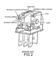
- Figure 2 is a perspective view showing the assembled components of a prior art relay shown with the relay cover removed.
- Figure 3 is a perspective view of the spring and armature subassembly used in the prior art relay shown in Figure 2 .
- Figure 4 is a partial view of a spring and armature subassembly of another prior art relay.
- Figure 5 is a top view of the low noise relay assembly of this invention showing the armature and relay contacts in the normally closed position.
- Figure 6 is a top view similar to Figure 5 , but showing only a partial assembly including the frame, coil assembly, the armature and spring and the movable contact.
- Figure 7 is a top view similar to that of Figure 6 , with the armature engaged with the core in the normally open position.
- Figure 8 shows the deposition of a resin prior to curing on the relay spring in accordance with a second embodiment of this invention.
- Figure 9 shows the resin deposited in Figure 8 after settling or flowing out and being cured, adhering to both the relay armature and to the spring that can be deposited after the armature is mechanically attached to the spring and which will provide mechanical damping for audible noise reduction.
- an electromagnetic relay 2 in accordance with a first embodiment of this invention includes noise dampening means 20 positioned between the relay armature 4 and the movable spring 6.
- the armature 4 is pulled toward the relay magnetic subassembly (which can include the relay coil or winding 10, the relay core 8 and the relay bobbin 22) when the relay is energized.
- the spring 6 returns the armature 4 to its normally position shown in Figures 5 and 6 .
- the noise dampening means 20 reduces the acoustic noise generated by the relay during both the energizing (i.e., "pull-in") and de-energizing (i.e., "drop-out”) cycles. Since acoustic noise can be magnified by resonance due to the relay structure, including the base, spring, cover and frame, a reduction in the noise due to impact will be cumulative.
- Noise dampening means 20 can be added to many types of electromagnetic relays without adversely affecting the operation of the relay.
- the prior art electromagnetic relay shown in Figures 1-3 is a conventional relay including both normally open and normally closed stationary contacts.
- a movable contact is shifted between the two stationary contacts by the presence or absence of a magnetic force generated by a current flowing through a coil or winding.
- An armature is moved into engagement with a core, extending through the coil or winding, when a current is applied to the coil to generate a pull in force.
- the armature is attached to a movable spring, and the electromagnetic force generated by the field established by current flowing through the coil must be sufficient to overcome a restoring force generated by the movable spring.
- the movable contact is mounted on the end of the movable spring.
- the portion of the movable spring on which the movable contact is mounted extends beyond the armature, which comprises a relatively rigid ferromagnetic member.
- the opposite end of the L-shaped movable spring is fixed to the frame, which also comprises a relatively rigid member.
- a rear edge of the armature abuts an adjacent edge of the frame, and the movable spring extends around these abutting edges at least through a right angle so that the spring will generate a restoring force that will tend to move the armature away from the coil.
- the armature will be spaced from the core.
- the armature is positioned so that when the armature engages the core, the armature will be tilted relative to the core. In other words, the abutting edge of the frame is laterally spaced beyond the exterior face of the core. This tilt or inclination is best seen in Figure 7 , which shows the armature 4 including the noise dampening means 20.
- the armature is also inclined when in engagement with the core. This inclination or tilt insures that the armature and the core will engage at prescribed points to insure reliable operation within appropriate dimensional manufacturing tolerances.
- a noise dampening means in accordance with this invention could be employed on relays in which the precise orientation of the armature and the coil may differ from that depicted herein.
- a noise dampening means can be used on a relay in which the armature and the coil engage each other on flat, substantially parallel surfaces.
- Direct contact or near direct contact between the armature and the core at the end of the pull-in switching operation is important to relay performance.
- Direct contact so that only very small gaps exist between the armature and the core, provides a very large magnetic force, which essentially locks the two components together.
- High resistance to vibration and shock are primary benefits as is a low drop-out voltage, making the relay less sensitive to voltage variations after it has closed.
- This overtravel is achieved in the prior art relay because all of the attractive force is generated by the action of the electromagnetic field on the armature, which is the largest movable mass.
- the overtravel is achieved by having the movable contact engage the normally open contact prior to engagement of the armature with the core.
- the overtravel spring easily doubles the separation force during the short time when the contacts are still engaged.
- the magnetic force on the armature increases almost exponentially as the gap between the core and the armature is reduced. Typically the magnetic force over much of the range of motion of the armature grows at a similar rate to the increase in the resisting spring force. However, during the second half of overtravel, the magnetic force dramatically increases relative to the spring force. A strong impact between the armature and the core will generate more acoustic noise, but a larger attractive force will also generate greater mating velocity, which will reduce the possibility of undesirable arcing during mating. A high mating velocity and a rapid build up of force ensures that the contacts have sufficient contact area during inrush current inherent to lamp loads to prevent contact overheating, melting and welding. Therefore, a large attractive force is desirable, even though it will result in more acoustic noise.
- the improved acoustic performance of electromagnetic relays incorporating the embodiments is premised upon the realization that a significant and noticeable contribution to acoustic noise is due to the noise generated by the armature in a relay of relatively standard design.
- the impact of the armature against the coil core causes an impulse that excites the relay structure during pull-in.
- the armature will impact against the spring arm in some designs.
- the contact impacts will be the source of noise during drop-out.
- the possible impact with the spring is a result of pre-bias and is not related to stopping the opening motion of the armature. In all designs the armature must be stopped by some means.
- the embodiments reduce acoustic noise generated by the armature by absorbing impact between the armature and the spring and damping spring vibrations as the armature reaches its fully open or fully closed positions.
- Figures 5-7 show noise dampening means 20 sandwiched between the armature 4 and the spring 6 in an otherwise conventional electromagnetic relay 2.
- the resilient spring 6 is attached to frame 16.
- the armature 4, noise dampening means 20 and spring 6 form a subassembly that extends along two sides of a magnetic subassembly comprising a coil or winding 10, a bobbin 22, a core 8 and the frame 18.
- the movable contact 12 is mounted on the movable flexible spring 6 between a normally closed contact 14 and a normally open contact 16.
- Figure 5 shows the assembly in an open or drop-out position in which the movable contact 12 is engaged with the normally closed contact 14 and the armature 4 is spaced from the core 8. In this position, insufficient electromagnetic force exists to pull the armature 4 toward the core 8.
- Figure 6 is a partial assembly of components in the same position as shown in Figure 5 .
- the relay base, the contacts 14 and 16 are not shown so that the position of the noise dampening means 20 in relation to the armature 4 and the core 8 is more readily seen.
- Figure 7 shows the position of the armature 4 relative to the core 8 in the full pull-in position.
- the core 8 has a circular cross sectional shape and the point of primary contact between the armature 4 and the core 8 is along the periphery of the core 8 in the area furthest from the frame 18.
- the tilted or inclined position of the armature 4, relative to the core 8, is clearly shown.
- the tilted orientation of the armature 4, which locally extends at an acute angle relative to the core 8, is not appreciably different from the orientation for a standard relay.
- a number of materials may be used to advantage as the noise dampening means 20.
- Urethanes are rated to 155°C, which may seem sufficient for a relay having a maximum relay ambient temperature of 125°C. However, in some applications internal temperatures within the relay can be as high as 180°C during worst-case conditions. Degradation of the urethane over time may result from these conditions. Initial experiments show that degradation does not impact relay performance, but the sound reduction capabilities are adversely affected. Urethane becomes substantially harder at operating temperature of -30°C, which might have deleterious effects on the performance of the relay. However, despite these drawbacks, urethane would appear to be a suitable material for noise reduction in some circumstances.
- Silicone exhibits almost ideal hardness and temperature range characteristics for use in forming the dampening layer 20.
- most silicones can out-gas volatile, uncured material.
- the out-gassed material can deposit on nearby surfaces, including the contacts in the relay. When exposed to heat from the arcing that can occur within the relay, there deposits can form an electrically insulating glass coating on the contacts, rendering the relay inoperative.
- specially formulated silicone compositions are commercially available which have low out-gassing characteristics. Many of these formulations were designed for space-related applications under extreme conditions of high temperature and vacuum which tend to dramatically accelerate out-gassing. These and other low volatility silicones could be acceptable for use inside a relay, especially in the very small amounts needed to practice this invention.
- the noise dampening means need not be a continuous sheet form. Indeed, from a manufacturing standpoint, the noise dampening means may be formed by use of a semi-liquid material, such as a caulk. It has been found that 2 drops of a low out-gassing silicone caulk positioned between the armature and the spring is sufficient to obtain significant noise reduction (i.e., the sound pressure level (or SPL) RMS fast response at 100mm from a microphone will be below 60 dBa).
- SPL sound pressure level
- a cold cast multiple component resin may also be used to form the noise dampening means 20.
- a multi-component resin can be deposited between the armature and the spring and subsequently cured.
- One suitable hydrocarbon based resin that is isocyanate-free and silicone-free is Guronic® DOFRO, which is commercially available from Paul Jordan Elektrotechnische Fabrik GmbH & Co. KG, Berlin, Germany. This standard composition can also be modified to adjust both pot life times and cure times for more efficient fabrication of the spring-armature subassembly.
- the noise dampening means is positioned between the armature and the spring. While these embodiments result in appreciable noise reduction in the relay, they can complicate the manufacturing process because the noise dampening means must be applied before the armature and spring are attached together, such as, for example, by a pair of spin rivets 28. To address this potential disadvantage, the alternate embodiment of Figures 8-9 simplifies manufacture of the armature-spring subassembly by permitting deposition of the noise dampening means after the armature has been mechanically attached to the spring.
- the noise dampening means is deposited on the surface of the spring 6 adjacent an edge 30 of the armature 4 as shown in Figure 8 .
- Edge 30 extends transversely relative to the inner spring surface on which the noise dampening means is deposited.
- Edge 30 is the edge of the armature that faces the movable contact 12 attached to the end of the spring 6.
- Particularly preferred noise dampening means for these embodiments include resins that will adhere to both the edge 30 of the armature 4 and to the spring 6.
- FIG. 8 One method of depositing a suitable material is shown in Figure 8 , where two drops 32 of a resin material are deposited on the spring 6 adjacent to edge 30 of the armature 4. The material flows laterally until the drops 32 coalesce to form a bead 34 covering the juncture between the spring 6 and the edge 30 of armature 4. The resin material is then cured in the normal manner.
- the resin bead 34 is located between the armature 4 and the movable relay contact 12, which will be mounted in hole 36 on the end of the spring 6 as shown in Figures 8 and 9 . It also follows that the resin bead 34 is located between the mechanical snap rivets 28, forming the main mechanical attachment of the armature to the spring, and the movable contacts 12. That portion of the spring 6 extending between the armature 4 and the movable contact 12 will remain free to flex when the movable contact 12 engages one of the stationary contacts 14, 16.
- a suitable resin for use in the embodiment of Figures 8 and 9 is Guronic® DOFRO casting resin, a two-component hydrocarbon based, isocyanate-free and silicone-free curable resin that is commercially available from Paul Jordan Elektrotechnische Fabrik GmbH & Co. KG, Berlin Germany.
- Guronic® DOFRO casting resin a two-component hydrocarbon based, isocyanate-free and silicone-free curable resin that is commercially available from Paul Jordan Elektrotechnische Fabrik GmbH & Co. KG, Berlin Germany.
- This resin when cured, remains relatively soft and has a Shore A hardness of approximately 30. It is nontoxic, environmentally safe, requires no special safety precautions, has excellent adhesion, good temperature resistance, high mechanical attenuation, and exhibits very little shrinkage during cure.
- This relatively viscous material deposited in this manner described above has been found to exhibit mechanical damping sufficient to reduce the noise generated by the relay during pull-in and drop-out.
- This noise dampening means in these embodiments is not limited to the use of the specific resin that is discussed with reference to the embodiment of Figures 8 and 9 .
- Other material may also be used.
- the disadvantages of polyurethanes and silicone resins have been previously discussed, but in some applications these alternative materials may be acceptable.
- Other resinous or non-resinous compositions may also result in reduction of the audible acoustic relay noise, and might be substituted for the specific material preferred for use with this second embodiment of the invention.
Landscapes
- Physics & Mathematics (AREA)
- Electromagnetism (AREA)
- Electromagnets (AREA)
- Arc-Extinguishing Devices That Are Switches (AREA)
Claims (16)
- Elektromagnetisches Relais, das Folgendes umfasst:a) eine magnetische Unterbaugruppe, die eine Spule (10) einschließt, die einen Kern (8) umgibt,b) einen Anker (4), der bewegt werden kann, zwischen einer ersten Position in Berührung mit dem Kern (8) und einer zweiten Position mit Zwischenraum zu dem Kern (8), wobei der Anker (4) als Reaktion auf das Erzeugen eines Magnetfeldes in dem Kern (8) bewegt werden kann,c) eine Feder (6), die den Anker (4) in die zweite Position vorspannt, und dadurch gekennzeichnet, dass es Folgendes umfasst:d) Geräuschdämpfungsmittel (20), die an der Verbindungsstelle zwischen dem Anker und der Feder angeordnet sind.
- Elektromagnetisches Relais nach Anspruch 1, wobei der Anker im Verhältnis zu dem Kern geneigt ist, wenn er sich in Eingriff mit dem Kern befindet.
- Elektromagnetisches Relais nach Anspruch 1, wobei ein beweglicher Kontakt an der Feder angebracht ist und eine elektrische Verbindung mit einem Arbeitskontakt, wenn sich der Anker in der ersten Position befindet, und einem Ruhekontakt, wenn sich der Anker in der zweiten Position befindet, herstellt.
- Elektromagnetisches Relais nach Anspruch 1, wobei das Relais Geräuschpegel von weniger als 60 dB(A) erzeugt.
- Elektromagnetisches Relais nach Anspruch 1, wobei das Geräuschdämpfungsmittel eine Lage eines Geräusch dämpfenden Werkstoffs umfasst, die zwischen der Feder und dem Anker angeordnet ist.
- Elektromagnetisches Relais nach Anspruch 5, wobei das Geräuschdämpfungsmittel eine Lage eines halbflüssigen Werkstoffs umfasst.
- Relais nach Anspruch 1, wobei das Geräuschdämpfungsmittel längs einer Kante des Ankers, die an die Feder angrenzt, angeordnet ist.
- Elektromagnetisches Relais nach Anspruch 7, wobei das Geräuschdämpfungsmittel ein Harz umfasst.
- Elektromagnetisches Relais nach Anspruch 8, wobei das Harz eine ausgehärtete Zweikomponenten-Harzzusammensetzung umfasst.
- Elektromagnetisches Relais nach Anspruch 8, wobei der Anker mechanisch an der Feder befestigt ist.
- Elektromagnetisches Relais nach Anspruch 10, wobei das Harz an einer Position längs der Feder angeordnet ist, die mit Zwischenraum zu der mechanischen Befestigung des Ankers an der Feder angeordnet ist.
- Elektromagnetisches Relais nach Anspruch 11, wobei das Harz an einer Position längs der Feder zwischen der mechanischen Befestigung des Ankers an der Feder und einem an der Feder befestigten beweglichen Kontakt angeordnet ist.
- Elektromagnetisches Relais nach Anspruch 8, wobei das Harz an einer Position längs der Feder zwischen einem Punkt, an dem der Anker den Kern berührt, und einem an der Feder angebrachten beweglichen Kontakt angeordnet ist.
- Elektromagnetisches Relais nach Anspruch 8, wobei das Harz die Biegung der Feder im Verhältnis zu dem Anker einschränkt.
- Elektromagnetisches Relais nach Anspruch 8, wobei das Harz eine isocyanatfreie und silikonfreie Zweikomponenten-Kaltvergusszusammensetzung auf Kohlenwasserstoffgrundlage umfasst.
- Elektromagnetisches Relais nach Anspruch 8, wobei das Harz nur auf den Oberflächen an dem Anker vorhanden ist, die den Kern nicht in Eingriff nehmen.
Applications Claiming Priority (3)
| Application Number | Priority Date | Filing Date | Title |
|---|---|---|---|
| US39321302P | 2002-07-01 | 2002-07-01 | |
| US393213P | 2002-07-01 | ||
| PCT/US2003/019378 WO2004003953A1 (en) | 2002-07-01 | 2003-06-19 | Low noise relay |
Publications (2)
| Publication Number | Publication Date |
|---|---|
| EP1518252A1 EP1518252A1 (de) | 2005-03-30 |
| EP1518252B1 true EP1518252B1 (de) | 2008-11-26 |
Family
ID=30000975
Family Applications (1)
| Application Number | Title | Priority Date | Filing Date |
|---|---|---|---|
| EP03739215A Expired - Lifetime EP1518252B1 (de) | 2002-07-01 | 2003-06-19 | Schallreduziertes relais |
Country Status (9)
| Country | Link |
|---|---|
| US (1) | US6794966B2 (de) |
| EP (1) | EP1518252B1 (de) |
| JP (1) | JP4293550B2 (de) |
| KR (1) | KR20050009766A (de) |
| CN (1) | CN100411079C (de) |
| AU (1) | AU2003245586A1 (de) |
| CA (1) | CA2491489C (de) |
| DE (1) | DE60324926D1 (de) |
| WO (1) | WO2004003953A1 (de) |
Families Citing this family (12)
| Publication number | Priority date | Publication date | Assignee | Title |
|---|---|---|---|---|
| EP1778669A2 (de) * | 2004-08-18 | 2007-05-02 | Takeda San Diego, Inc. | Kinase-inhibitoren |
| JP2008053152A (ja) * | 2006-08-28 | 2008-03-06 | Omron Corp | 静音型電磁継電器 |
| US7548146B2 (en) * | 2006-12-27 | 2009-06-16 | Tyco Electronics Corporation | Power relay |
| DE102007014405B4 (de) | 2007-03-26 | 2010-05-27 | Frank Deinzer | Verfahren zur Worterkennung in Zeichensequenzen |
| DE102012006450A1 (de) * | 2012-03-30 | 2013-10-02 | Phoenix Contact Gmbh & Co. Kg | Relais mit zwangsgeführten Kontakten |
| CN103910891B (zh) * | 2014-03-13 | 2016-04-13 | 中科院广州化学有限公司南雄材料生产基地 | 一种对位芳纶的溶解方法及其应用 |
| DE102015201703A1 (de) | 2015-01-30 | 2016-08-04 | Te Connectivity Germany Gmbh | Geräuscharm schaltende elektrische Schaltvorrichtung |
| CN106586525A (zh) * | 2015-10-15 | 2017-04-26 | 吴志敏 | 一种自动上料取料旋铆机 |
| JP6668997B2 (ja) | 2016-07-29 | 2020-03-18 | オムロン株式会社 | 電磁継電器 |
| US10978266B2 (en) * | 2018-04-24 | 2021-04-13 | Te Connectivity Corporation | Electromechanical switch having movable contact and dampener |
| CN110233083B (zh) * | 2019-06-27 | 2025-05-13 | 迅达(中国)电梯有限公司 | 用于安装接触器的安装装置 |
| JP7361593B2 (ja) | 2019-12-19 | 2023-10-16 | 富士通コンポーネント株式会社 | 電磁継電器 |
Family Cites Families (10)
| Publication number | Priority date | Publication date | Assignee | Title |
|---|---|---|---|---|
| GB1582352A (en) * | 1977-03-08 | 1981-01-07 | Solartron Electronic Group | Electrical switching apparatus |
| US4460881A (en) * | 1982-09-30 | 1984-07-17 | Meister Jack B | Quiet relay |
| JPS62223931A (ja) | 1986-03-25 | 1987-10-01 | 松下電工株式会社 | 電磁継電器 |
| JP2694786B2 (ja) * | 1991-10-25 | 1997-12-24 | 日本電気株式会社 | 電磁継電器 |
| JPH05174684A (ja) * | 1991-12-19 | 1993-07-13 | Fujitsu Ltd | 低動作音型電磁リレー |
| US5389905A (en) * | 1992-04-22 | 1995-02-14 | Matsushita Electric Works, Ltd. | Damper, electromagnet assembly employing the damper, and relay employing the electromagnet assemblies |
| JPH0652774A (ja) * | 1992-07-30 | 1994-02-25 | Nec Corp | 電磁継電器 |
| US5321377A (en) * | 1993-01-21 | 1994-06-14 | Kaloust P. Sagoian | Electromagnet for relays and contactor assemblies |
| JP2002100274A (ja) * | 2000-09-26 | 2002-04-05 | Omron Corp | 電磁リレー |
| JP3903713B2 (ja) | 2000-12-13 | 2007-04-11 | アンデン株式会社 | 電磁継電器 |
-
2003
- 2003-05-09 US US10/434,832 patent/US6794966B2/en not_active Expired - Fee Related
- 2003-06-19 CA CA2491489A patent/CA2491489C/en not_active Expired - Fee Related
- 2003-06-19 DE DE60324926T patent/DE60324926D1/de not_active Expired - Lifetime
- 2003-06-19 KR KR10-2004-7021568A patent/KR20050009766A/ko not_active Ceased
- 2003-06-19 AU AU2003245586A patent/AU2003245586A1/en not_active Abandoned
- 2003-06-19 JP JP2004517693A patent/JP4293550B2/ja not_active Expired - Fee Related
- 2003-06-19 WO PCT/US2003/019378 patent/WO2004003953A1/en not_active Ceased
- 2003-06-19 CN CNB038155877A patent/CN100411079C/zh not_active Expired - Fee Related
- 2003-06-19 EP EP03739215A patent/EP1518252B1/de not_active Expired - Lifetime
Also Published As
| Publication number | Publication date |
|---|---|
| CN100411079C (zh) | 2008-08-13 |
| US20040000981A1 (en) | 2004-01-01 |
| CA2491489C (en) | 2011-08-16 |
| CA2491489A1 (en) | 2004-01-08 |
| US6794966B2 (en) | 2004-09-21 |
| WO2004003953A1 (en) | 2004-01-08 |
| JP2005531903A (ja) | 2005-10-20 |
| AU2003245586A1 (en) | 2004-01-19 |
| CN1666309A (zh) | 2005-09-07 |
| JP4293550B2 (ja) | 2009-07-08 |
| KR20050009766A (ko) | 2005-01-25 |
| DE60324926D1 (de) | 2009-01-08 |
| EP1518252A1 (de) | 2005-03-30 |
Similar Documents
| Publication | Publication Date | Title |
|---|---|---|
| EP1376636B1 (de) | Schallreduziertes Relais | |
| EP1518252B1 (de) | Schallreduziertes relais | |
| US7157996B2 (en) | Electromagnetic switching device | |
| JP6141191B2 (ja) | 燃料を噴射する弁 | |
| US7423504B2 (en) | Electromagnetic relay | |
| JP4439822B2 (ja) | 電磁弁 | |
| CN112189247A (zh) | 具有可移动触头和阻尼器的机电开关 | |
| US20070084633A1 (en) | Electromagnetic relay with noise reducing sealant | |
| US11515112B2 (en) | Electromagnetic relay | |
| JP3903713B2 (ja) | 電磁継電器 | |
| JP2001254865A (ja) | 電磁弁 | |
| JP2694786B2 (ja) | 電磁継電器 | |
| JP2002110014A (ja) | 電磁継電器 | |
| US20200388447A1 (en) | An electrical switch and a switching blade therefor | |
| JPH05174684A (ja) | 低動作音型電磁リレー | |
| GB2400736A (en) | Latching relay | |
| KR100676346B1 (ko) | 정음형 릴레이 | |
| KR200388598Y1 (ko) | 정음형 릴레이 | |
| NZ743680B (en) | An electrical switch and a switching blade therefor | |
| JPH0810657B2 (ja) | 電磁石装置 |
Legal Events
| Date | Code | Title | Description |
|---|---|---|---|
| PUAI | Public reference made under article 153(3) epc to a published international application that has entered the european phase |
Free format text: ORIGINAL CODE: 0009012 |
|
| 17P | Request for examination filed |
Effective date: 20050107 |
|
| AK | Designated contracting states |
Kind code of ref document: A1 Designated state(s): AT BE BG CH CY CZ DE DK EE ES FI FR GB GR HU IE IT LI LU MC NL PT RO SE SI SK TR |
|
| AX | Request for extension of the european patent |
Extension state: AL LT LV MK |
|
| DAX | Request for extension of the european patent (deleted) | ||
| RBV | Designated contracting states (corrected) |
Designated state(s): DE FR GB IT |
|
| GRAP | Despatch of communication of intention to grant a patent |
Free format text: ORIGINAL CODE: EPIDOSNIGR1 |
|
| GRAS | Grant fee paid |
Free format text: ORIGINAL CODE: EPIDOSNIGR3 |
|
| GRAA | (expected) grant |
Free format text: ORIGINAL CODE: 0009210 |
|
| AK | Designated contracting states |
Kind code of ref document: B1 Designated state(s): DE FR GB IT |
|
| REG | Reference to a national code |
Ref country code: GB Ref legal event code: FG4D |
|
| REF | Corresponds to: |
Ref document number: 60324926 Country of ref document: DE Date of ref document: 20090108 Kind code of ref document: P |
|
| PLBE | No opposition filed within time limit |
Free format text: ORIGINAL CODE: 0009261 |
|
| STAA | Information on the status of an ep patent application or granted ep patent |
Free format text: STATUS: NO OPPOSITION FILED WITHIN TIME LIMIT |
|
| 26N | No opposition filed |
Effective date: 20090827 |
|
| PGFP | Annual fee paid to national office [announced via postgrant information from national office to epo] |
Ref country code: FR Payment date: 20110629 Year of fee payment: 9 |
|
| PGFP | Annual fee paid to national office [announced via postgrant information from national office to epo] |
Ref country code: GB Payment date: 20110628 Year of fee payment: 9 |
|
| PGFP | Annual fee paid to national office [announced via postgrant information from national office to epo] |
Ref country code: IT Payment date: 20110623 Year of fee payment: 9 |
|
| PGFP | Annual fee paid to national office [announced via postgrant information from national office to epo] |
Ref country code: DE Payment date: 20110629 Year of fee payment: 9 |
|
| GBPC | Gb: european patent ceased through non-payment of renewal fee |
Effective date: 20120619 |
|
| PG25 | Lapsed in a contracting state [announced via postgrant information from national office to epo] |
Ref country code: IT Free format text: LAPSE BECAUSE OF NON-PAYMENT OF DUE FEES Effective date: 20120619 |
|
| REG | Reference to a national code |
Ref country code: FR Ref legal event code: ST Effective date: 20130228 |
|
| REG | Reference to a national code |
Ref country code: DE Ref legal event code: R119 Ref document number: 60324926 Country of ref document: DE Effective date: 20130101 |
|
| PG25 | Lapsed in a contracting state [announced via postgrant information from national office to epo] |
Ref country code: GB Free format text: LAPSE BECAUSE OF NON-PAYMENT OF DUE FEES Effective date: 20120619 Ref country code: DE Free format text: LAPSE BECAUSE OF NON-PAYMENT OF DUE FEES Effective date: 20130101 Ref country code: FR Free format text: LAPSE BECAUSE OF NON-PAYMENT OF DUE FEES Effective date: 20120702 |