EP1517851B1 - Methode und vorrichtung zur herstellung von ammoniaksynthesegas - Google Patents
Methode und vorrichtung zur herstellung von ammoniaksynthesegas Download PDFInfo
- Publication number
- EP1517851B1 EP1517851B1 EP03735386A EP03735386A EP1517851B1 EP 1517851 B1 EP1517851 B1 EP 1517851B1 EP 03735386 A EP03735386 A EP 03735386A EP 03735386 A EP03735386 A EP 03735386A EP 1517851 B1 EP1517851 B1 EP 1517851B1
- Authority
- EP
- European Patent Office
- Prior art keywords
- stage
- mixer
- synthesis gas
- flow
- compressor
- Prior art date
- Legal status (The legal status is an assumption and is not a legal conclusion. Google has not performed a legal analysis and makes no representation as to the accuracy of the status listed.)
- Expired - Lifetime
Links
Images

Classifications
-
- C—CHEMISTRY; METALLURGY
- C01—INORGANIC CHEMISTRY
- C01C—AMMONIA; CYANOGEN; COMPOUNDS THEREOF
- C01C1/00—Ammonia; Compounds thereof
- C01C1/02—Preparation, purification or separation of ammonia
- C01C1/04—Preparation of ammonia by synthesis
- C01C1/0405—Preparation of ammonia by synthesis from N2 and H2 in presence of a catalyst
-
- B—PERFORMING OPERATIONS; TRANSPORTING
- B01—PHYSICAL OR CHEMICAL PROCESSES OR APPARATUS IN GENERAL
- B01F—MIXING, e.g. DISSOLVING, EMULSIFYING OR DISPERSING
- B01F25/00—Flow mixers; Mixers for falling materials, e.g. solid particles
- B01F25/30—Injector mixers
- B01F25/31—Injector mixers in conduits or tubes through which the main component flows
- B01F25/312—Injector mixers in conduits or tubes through which the main component flows with Venturi elements; Details thereof
- B01F25/3124—Injector mixers in conduits or tubes through which the main component flows with Venturi elements; Details thereof characterised by the place of introduction of the main flow
- B01F25/31242—Injector mixers in conduits or tubes through which the main component flows with Venturi elements; Details thereof characterised by the place of introduction of the main flow the main flow being injected in the central area of the venturi, creating an aspiration in the circumferential part of the conduit
-
- C—CHEMISTRY; METALLURGY
- C01—INORGANIC CHEMISTRY
- C01B—NON-METALLIC ELEMENTS; COMPOUNDS THEREOF; METALLOIDS OR COMPOUNDS THEREOF NOT COVERED BY SUBCLASS C01C
- C01B3/00—Hydrogen; Gaseous mixtures containing hydrogen; Separation of hydrogen from mixtures containing it; Purification of hydrogen; Reversible storage of hydrogen
- C01B3/02—Production of hydrogen; Production of gaseous mixtures containing hydrogen
- C01B3/025—Preparation or purification of gas mixtures for ammonia synthesis
-
- C—CHEMISTRY; METALLURGY
- C01—INORGANIC CHEMISTRY
- C01B—NON-METALLIC ELEMENTS; COMPOUNDS THEREOF; METALLOIDS OR COMPOUNDS THEREOF NOT COVERED BY SUBCLASS C01C
- C01B3/00—Hydrogen; Gaseous mixtures containing hydrogen; Separation of hydrogen from mixtures containing it; Purification of hydrogen; Reversible storage of hydrogen
- C01B3/50—Separation of hydrogen or hydrogen-containing gases from gaseous mixtures, e.g. purification
- C01B3/52—Separation of hydrogen or hydrogen-containing gases from gaseous mixtures, e.g. purification by contacting with liquids; Regeneration of used liquids
-
- B—PERFORMING OPERATIONS; TRANSPORTING
- B01—PHYSICAL OR CHEMICAL PROCESSES OR APPARATUS IN GENERAL
- B01F—MIXING, e.g. DISSOLVING, EMULSIFYING OR DISPERSING
- B01F23/00—Mixing according to the phases to be mixed, e.g. dispersing or emulsifying
- B01F23/20—Mixing gases with liquids
- B01F23/23—Mixing gases with liquids by introducing gases into liquid media, e.g. for producing aerated liquids
-
- C—CHEMISTRY; METALLURGY
- C01—INORGANIC CHEMISTRY
- C01B—NON-METALLIC ELEMENTS; COMPOUNDS THEREOF; METALLOIDS OR COMPOUNDS THEREOF NOT COVERED BY SUBCLASS C01C
- C01B2203/00—Integrated processes for the production of hydrogen or synthesis gas
- C01B2203/04—Integrated processes for the production of hydrogen or synthesis gas containing a purification step for the hydrogen or the synthesis gas
- C01B2203/0415—Purification by absorption in liquids
-
- C—CHEMISTRY; METALLURGY
- C01—INORGANIC CHEMISTRY
- C01B—NON-METALLIC ELEMENTS; COMPOUNDS THEREOF; METALLOIDS OR COMPOUNDS THEREOF NOT COVERED BY SUBCLASS C01C
- C01B2203/00—Integrated processes for the production of hydrogen or synthesis gas
- C01B2203/04—Integrated processes for the production of hydrogen or synthesis gas containing a purification step for the hydrogen or the synthesis gas
- C01B2203/0465—Composition of the impurity
- C01B2203/0475—Composition of the impurity the impurity being carbon dioxide
-
- C—CHEMISTRY; METALLURGY
- C01—INORGANIC CHEMISTRY
- C01B—NON-METALLIC ELEMENTS; COMPOUNDS THEREOF; METALLOIDS OR COMPOUNDS THEREOF NOT COVERED BY SUBCLASS C01C
- C01B2203/00—Integrated processes for the production of hydrogen or synthesis gas
- C01B2203/04—Integrated processes for the production of hydrogen or synthesis gas containing a purification step for the hydrogen or the synthesis gas
- C01B2203/0465—Composition of the impurity
- C01B2203/0495—Composition of the impurity the impurity being water
-
- Y—GENERAL TAGGING OF NEW TECHNOLOGICAL DEVELOPMENTS; GENERAL TAGGING OF CROSS-SECTIONAL TECHNOLOGIES SPANNING OVER SEVERAL SECTIONS OF THE IPC; TECHNICAL SUBJECTS COVERED BY FORMER USPC CROSS-REFERENCE ART COLLECTIONS [XRACs] AND DIGESTS
- Y02—TECHNOLOGIES OR APPLICATIONS FOR MITIGATION OR ADAPTATION AGAINST CLIMATE CHANGE
- Y02P—CLIMATE CHANGE MITIGATION TECHNOLOGIES IN THE PRODUCTION OR PROCESSING OF GOODS
- Y02P20/00—Technologies relating to chemical industry
- Y02P20/50—Improvements relating to the production of bulk chemicals
- Y02P20/52—Improvements relating to the production of bulk chemicals using catalysts, e.g. selective catalysts
Definitions
- the present invention refers, in its most general aspect, to a method and relative apparatus for ammonia production through a catalytic reaction of synthesis gas, comprising hydrogen and nitrogen, previously pressurised in a suitable compressor with two or more stages.
- this invention concerns a method of the aforementioned type in which a purification step of the synthesis gas is provided for through separation of water and carbon dioxide contained therein, carried out in correspondence with an intermediate stage of said compressor.
- the present invention refers to a method of the considered type, in which the synthesis gas is collected when exiting from a predetermined stage of said compressor, is purified and cooled at a predetermined temperature, through washing with substantially anhydrous liquid ammonia, and then is fed again into a stage of said compressor, after the one from which it was collected.
- the methods most widely adopted by the prior art are based upon the use of recycled liquid ammonia for a washing step and concurrent rapid cooling of the synthesis gas, which is then sent to the reactor. But besides the substantial operating costs the chilling unit and the recondensation of the ammonia vaporised there, the aforementioned methods involve increased costs for the necessary subsequent step of heating the purified gas to the predetermined temperature of entry into the reactor.
- these compression stages are indicated as compression stages of the "make-up" synthesis gas, with which is associated the final compression stage, known as the recycling stage since it is used for the compression and recycling into the reactor of the unreacted gases coming from the synthesis section as well as of the compressed make-up gas.
- the purification method according to the prior art has different recognised technical drawbacks.
- the synthesis gas crossing the washing column for its purification undergoes a predetermined pressure drop.
- This pressure drop must be necessarily recovered downstream of such washing with the consequent energy consumptions of the compressor.
- this type of purification causes an appreciable evaporation of the liquid washing ammonia that is thus absorbed by the flow of synthesis gas and thus inevitably recycled in the reactor at the expense of the conversion yield thereof.
- a reduction in the conversion yield of the reactor has, moreover, as a consequence, an increase in the amount of unreacted substances that have to be separated from the flow of ammonia produced and to be recycled to the reactor, with consequent overloads at the sections intended for such operations and high energy consumptions.
- the problem at the base of the present invention is that of providing a method for synthesis ammonia production of the type considered above, in which the purification system of the synthesis gas has functional characteristics so as to overcome the drawbacks quoted above with reference to the prior art and in particular so as to allow a substantial energy saving compared to the methods used up to now.
- said flow of synthesis gas is cooled to a temperature of between +8°/-20°C, before being fed into said mixer.
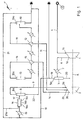
- a plant for the production of ammonia is globally schematically indicated with P, comprising an apparatus for carrying out the method of the present invention, which comprises a compressor with many stages, of which just the longitudinal axis A is shown, and where with 1 and 2 two subsequent stages thereof are schematically indicated, aligned and adjacent on said axis A.
- a compressor is a two stage compressor, of which one is for what is known as make-up gas compression and a final stage for what.is known as recycling compression.
- the stage 1 has an inlet 1a (or suction end) in fluid communication with a source 3 of synthesis gas through a line 4 and has an outlet 1b (or discharge end) in fluid communication with a first gas-liquid separator 5, through a line 6 and a cooling group 7.
- the stage 2 has a first inlet 2a in fluid communication with the head 8a of a second gas-liquid separator 8, through a respective line 9, and a second inlet 2b in fluid communication with the head 10a of a third gas-liquid separator 10, through a line 11 and a cooling group 12.
- the outlet 2c of said stage 2 is in fluid communication with the head 13a of an ammonia synthesis reactor 13, through a line 14 and a respective cooling group 15.
- the apparatus of fig. 1 comprises a mixer 16, in fluid communication, on one side, with said separator 8, through a line 17 and, on the other side, with the head 5a of the separator 5, through a line 18 and respective cooling group 19.
- said mixer 16 is positioned between the first and second stage. Moreover, it is preferably arranged in a substantially horizontal position with respect to the ground of the plant P.
- the synthesis gas coming out from the first compression stage 1 is fed to the cooling group 7 and then to the separator 5, where most of the water is separated from the gas and is discharged through the duct 20.
- the flow of said synthesis gas, thus dehydrated, is sent to the cooling group 19.
- the amount of liquid ammonia is such as to ensure, after cooling, a concentration of ammonia in liquid phase of between 25% and 50%, the rest being water.
- the synthesis gas is cooled to +8°/-20°C and in such a condition is fed axially into the mixer 16.
- said flow 21a of liquid ammonia is fed into the mixer 16 coaxially and in co-current with the synthesis gas.
- the temperature of the synthesis gas is thus preferably lowered to -20°/-27°C.
- a portion 16a of predetermined axial length of the aforementioned mixer 16 has a reduced cross-section.
- the flows of liquid ammonia and of reactant gases are advantageously accelerated and mixed together (mixing zone).
- the portion with a reduced cross-section 16a is followed by a second portion 16b with a constant cross-section, of a predetermined axial length, for spreading such flows.
- the portion 16b in turn goes into a third portion with a predetermined axial length, 16c, with an increasing cross-section, so as to slow down the speed of the fluids once mixed.
- an axial length of the first mixing portion 16a for example, of between 0.5 and 1 m.
- the axial length of the second portion 16b with a constant section was between 0.6 and 1.2 m.
- the feeding into the mixer 16 of the flow of liquid ammonia is carried out through a suitable distributor nozzle 23 arranged inside the portion 16a of the mixer and connected to the line 21a.
- the line 21a is in turn arranged inside the line 18 for feeding the flow of reactant gases, connected with the free end of the portion 16a of the mixer.
- the end part 23a of the nozzle 23 is equipped with appropriate openings or slits (not represented) which are suitably sized so as to allow the flow of liquid ammonia to come out in the form of a plurality of high-speed jets.
- the liquid ammonia and the water are separated from the synthesis gas and are discharged through the duct 22, whereas said dehydrated synthesis gases, coming out from the head 8a of the separator 8, are fed into (2a) the second stage 2 of the compressor, at a temperature of -20°/-27°C.
- the technical measure of using low temperature cooling (19) before the mixer 16 gives the advantage of reducing the amount of evaporated ammonia in the synthesis gas, and consequently further reducing the compression energy and at the same time improving the conversion yield of the synthesis reactor with respect to the prior art, with all of the advantages that it brings.
- the synthesis gas compressed to the predetermined value in the second stage of the compressor, is fed to the synthesis reactor 13, after being heatedin 15. From the reactor 13, the gaseous mixture comprising ammonia and unreacted gases is progressively cooled through a plurality of cooling groups (15, 12) and is fed to the separator 10. From this separator, the liquid ammonia thus obtained is sent for storage, whereas the gas, coming out from the head 10a thereof, is recycled into the second stage 2 of the compressor.
Landscapes
- Chemical & Material Sciences (AREA)
- Organic Chemistry (AREA)
- Chemical Kinetics & Catalysis (AREA)
- Inorganic Chemistry (AREA)
- Engineering & Computer Science (AREA)
- Combustion & Propulsion (AREA)
- Analytical Chemistry (AREA)
- Physical Or Chemical Processes And Apparatus (AREA)
- Organic Low-Molecular-Weight Compounds And Preparation Thereof (AREA)
- Catalysts (AREA)
- Industrial Gases (AREA)
- Separation By Low-Temperature Treatments (AREA)
Claims (10)
- Verfahren zur Herstellung von Ammoniak durch eine katalytische Reaktion eines unter Druck stehenden Synthesegases in einer geeigneten Verdichtungseinrichtung mit mehreren Stufen (1, 2), die jeweils mit einem Einlass und einem Auslass (1a, 2a, 1b, 2b, 2c) für das Synthesegas ausgestattet sind, wobei das Verfahren einen Reinigungsschritt durch flüssiges Ammoniak des Synthesegases von darin enthaltenem Wasser und Kohlendioxid umfasst, dadurch gekennzeichnet, dass die Reinigung folgende Prozessschritte umfasst:- Anordnen einer Mischvorrichtung (16) für Gas/Flüssigkeit in Fluidverbindung an einer Seite mit dem Auslass (1b) einer ersten Stufe (1) der Verdichtungseinrichtung oder mit dem Auslass einer Zwischenstufe davon, und an der anderen Seite mit dem Einlass (2b) einer Stufe (2), die der ersten Stufe (1) oder der Zwischenstufe unmittelbar nachgeschaltet ist, wobei die Mischvorrichtung (16) einen sich axial erstreckenden Abschnitt kleiner werdenden Querschnitts aufweist,- axiales Einleiten in die Mischvorrichtung (16) eines Stroms aus Synthesegas, der aus der ersten Stufe (1) oder aus der Zwischenstufe kommt, und zwar gleichzeitig mit einem Strom aus flüssigem Ammoniak, wobei die Ströme koaxial sind und im Gleichstrom laufen,- Abziehen eines im Wesentlichen wasserfreien Synthesegases aus dem Gemisch der Ströme, das aus der Mischvorrichtung (16) kommt, und Überführen des Gases in die Stufe (2), die der ersten Stufe (1) oder der Zwischenstufe nachgeschaltet ist.
- Verfahren nach Anspruch 1, dadurch gekennzeichnet, dass der Strom aus Synthesegas auf eine Temperatur zwischen +8 und -20°C gekühlt wird, bevor er in die Mischvorrichtung (16) eingeleitet wird.
- Verfahren nach Anspruch 2, dadurch gekennzeichnet, dass das Kühlen durch einen Strom aus flüssigem Ammoniak bewerkstelligt wird.
- Verfahren nach Anspruch 3, dadurch gekennzeichnet, dass das Kühlen stromaufwärts des Einlasses der koaxialen Ströme des Synthesegases und flüssigen Ammoniaks in die Mischvorrichtung (16) erfolgt.
- Verfahren nach Anspruch 1, dadurch gekennzeichnet, dass der Strom aus flüssigem Ammoniak in die Mischvorrichtung (16) in Form mehrerer Hochgeschwindigkeitsstrahlen eingeleitet wird.
- Verfahren nach Anspruch 5, dadurch gekennzeichnet, dass der Strom aus flüssigem Ammoniak in die Mischvorrichtung (16) eingeleitet wird, indem man ihn durch eine Düse (23) laufen lässt, die mit entsprechenden, geeignet bemessenen Öffnungen oder Schlitzen ausgestattet ist.
- Vorrichtung zum Ausführen des Verfahrens nach den Ansprüchen 1 bis 6, mit einer Verdichtungseinrichtung mit mehreren Stufen (1, 2), die jeweils mit einem Einlass und einem Auslass (1a, 2a, 1b, 2b, 2c) ausgestattet sind, dadurch gekennzeichnet, dass sie eine Mischvorrichtung (16) für Gas/Flüssigkeit aufweist, die an einer Seite in Fluidverbindung mit dem Auslass (1b) einer ersten Stufe (1) der Verdichtungseinrichtung oder mit dem Auslass einer Zwischenstufe davon steht, und an der anderen Seite mit dem Einlass (2b) einer Stufe (2), die der ersten Stufe (1) oder der Zwischenstufe unmittelbar nachgeschaltet ist, wobei die Mischvorrichtung (16) einen sich axial erstreckenden Abschnitt (16a) kleiner werdenden Querschnitts aufweist.
- Vorrichtung nach Anspruch 7, dadurch gekennzeichnet, dass zwischen der Mischvorrichtung (16) und der darauf folgenden Stufe (2) der Verdichtungseinrichtung eine Abtrennvorrichtung (8) für Gas/Flüssigkeit angeordnet ist.
- Vorrichtung nach Anspruch 8, dadurch gekennzeichnet, dass zwischen der Mischvorrichtung (16) und der ersten Stufe (1) der Verdichtungseinrichtung mindestens eine Kühleinheit (19) angeordnet ist.
- Vorrichtung nach Anspruch 7, dadurch gekennzeichnet, dass sie eine Düse (23) umfasst, die mit entsprechenden, geeignet bemessenen Öffnungen oder Schlitzen ausgestattet ist, die an einer Seite in Fluidverbindung mit dem Abschnitt (16a) verminderten Querschnitts der Mischvorrichtung (16) stehen, und an der entgegengesetzten Seite mit einer Leitung (21a) zum Einleiten eines Stroms aus flüssigem Ammoniak in die Mischvorrichtung (16).
Applications Claiming Priority (3)
| Application Number | Priority Date | Filing Date | Title |
|---|---|---|---|
| EP02014421A EP1375418A1 (de) | 2002-06-28 | 2002-06-28 | Verfahren und Vorrichtung zur Herstellung von Ammoniak-Synthesegas |
| EP02014421 | 2002-06-28 | ||
| PCT/EP2003/005049 WO2004002879A1 (en) | 2002-06-28 | 2003-05-14 | Method and apparatus for ammonia synthesis gas production |
Publications (2)
| Publication Number | Publication Date |
|---|---|
| EP1517851A1 EP1517851A1 (de) | 2005-03-30 |
| EP1517851B1 true EP1517851B1 (de) | 2006-09-06 |
Family
ID=29716863
Family Applications (2)
| Application Number | Title | Priority Date | Filing Date |
|---|---|---|---|
| EP02014421A Withdrawn EP1375418A1 (de) | 2002-06-28 | 2002-06-28 | Verfahren und Vorrichtung zur Herstellung von Ammoniak-Synthesegas |
| EP03735386A Expired - Lifetime EP1517851B1 (de) | 2002-06-28 | 2003-05-14 | Methode und vorrichtung zur herstellung von ammoniaksynthesegas |
Family Applications Before (1)
| Application Number | Title | Priority Date | Filing Date |
|---|---|---|---|
| EP02014421A Withdrawn EP1375418A1 (de) | 2002-06-28 | 2002-06-28 | Verfahren und Vorrichtung zur Herstellung von Ammoniak-Synthesegas |
Country Status (12)
| Country | Link |
|---|---|
| US (1) | US20050287063A1 (de) |
| EP (2) | EP1375418A1 (de) |
| CN (1) | CN100453445C (de) |
| AT (1) | ATE338730T1 (de) |
| BR (1) | BR0312087B1 (de) |
| CA (1) | CA2489101A1 (de) |
| DE (1) | DE60308185T2 (de) |
| DK (1) | DK1517851T3 (de) |
| EG (1) | EG24578A (de) |
| RU (1) | RU2309894C2 (de) |
| UA (1) | UA79126C2 (de) |
| WO (1) | WO2004002879A1 (de) |
Families Citing this family (6)
| Publication number | Priority date | Publication date | Assignee | Title |
|---|---|---|---|---|
| CN101659420B (zh) * | 2009-08-07 | 2012-02-15 | 上海国际化建工程咨询公司 | 一种氨合成新鲜气的干燥净化方法和装置 |
| CN102557076B (zh) * | 2010-12-08 | 2015-06-24 | 联仕(上海)电子化学材料有限公司 | 一种生产电子级氟化铵水溶液的方法 |
| JP6399867B2 (ja) * | 2014-09-05 | 2018-10-03 | 三菱重工エンジニアリング株式会社 | アンモニア合成システム及び方法 |
| CN110330034B (zh) * | 2019-06-12 | 2021-01-15 | 新沂市新南环保产业技术研究院有限公司 | 一种便于更换吸附材质的氨气逐级提纯装置 |
| US20250282629A1 (en) * | 2022-04-27 | 2025-09-11 | Thyssenkrupp Uhde Gmbh | Process for operating an ammonia synthesis with varying plant utilization |
| BE1030483B1 (de) * | 2022-04-27 | 2023-11-28 | Thyssenkrupp Ind Solutions Ag | Verfahren zum Betreiben einer Ammoniaksynthese mit schwankender Auslastung |
Family Cites Families (11)
| Publication number | Priority date | Publication date | Assignee | Title |
|---|---|---|---|---|
| US1815243A (en) * | 1923-05-12 | 1931-07-21 | Atmospheric Nitrogen Corp | Process of making ammonia by catalysis |
| US1830167A (en) * | 1925-03-26 | 1931-11-03 | Chemical Engineering Corp | Production of ammonia |
| US3484197A (en) * | 1965-10-29 | 1969-12-16 | Pullman Inc | Process for carrying out cyclic synthesis reactions at elevated pressures |
| US3349569A (en) * | 1966-02-14 | 1967-10-31 | Chemical Construction Corp | Anhydrous ammonia scrubbing of ammonia synthesis gas |
| DE2908263A1 (de) * | 1979-03-02 | 1980-09-11 | Hoechst Ag | Verfahren und vorrichtung zur absorption von gasen |
| SU1490079A1 (ru) * | 1986-11-24 | 1989-06-30 | Московский Институт Химического Машиностроения | Способ получени аммиака |
| SU1625826A1 (ru) * | 1987-05-18 | 1991-02-07 | Предприятие П/Я А-1676 | Способ получени аммиака |
| RU2022927C1 (ru) * | 1989-12-20 | 1994-11-15 | Государственный научно-исследовательский и проектный институт азотной промышленности и продуктов органического синтеза | Способ производства аммиака |
| US6019820A (en) * | 1997-05-07 | 2000-02-01 | E. I. Du Pont De Nemours And Company | Liquid jet compressor |
| CA2303554C (en) * | 1997-09-15 | 2008-07-29 | Den Norske Stats Oljeselskap A.S. | Separation of acid gas from natural gas |
| RU2261225C2 (ru) * | 2000-03-03 | 2005-09-27 | Проусесс Менеджмент Энтерпрайсиз Лтд. | Процесс синтеза аммиака и применяемая для этого установка |
-
2002
- 2002-06-28 EP EP02014421A patent/EP1375418A1/de not_active Withdrawn
-
2003
- 2003-05-14 US US10/519,743 patent/US20050287063A1/en not_active Abandoned
- 2003-05-14 DE DE60308185T patent/DE60308185T2/de not_active Expired - Lifetime
- 2003-05-14 RU RU2005102066/15A patent/RU2309894C2/ru active
- 2003-05-14 BR BRPI0312087-2A patent/BR0312087B1/pt active IP Right Grant
- 2003-05-14 CN CNB038152983A patent/CN100453445C/zh not_active Expired - Lifetime
- 2003-05-14 DK DK03735386T patent/DK1517851T3/da active
- 2003-05-14 CA CA002489101A patent/CA2489101A1/en not_active Abandoned
- 2003-05-14 EP EP03735386A patent/EP1517851B1/de not_active Expired - Lifetime
- 2003-05-14 AT AT03735386T patent/ATE338730T1/de not_active IP Right Cessation
- 2003-05-14 WO PCT/EP2003/005049 patent/WO2004002879A1/en not_active Ceased
- 2003-05-14 UA UAA200500744A patent/UA79126C2/uk unknown
- 2003-06-23 EG EG2003060601A patent/EG24578A/en active
Also Published As
| Publication number | Publication date |
|---|---|
| DE60308185T2 (de) | 2007-08-23 |
| RU2005102066A (ru) | 2005-09-10 |
| US20050287063A1 (en) | 2005-12-29 |
| RU2309894C2 (ru) | 2007-11-10 |
| BR0312087A (pt) | 2005-03-22 |
| EP1517851A1 (de) | 2005-03-30 |
| CN1665741A (zh) | 2005-09-07 |
| UA79126C2 (en) | 2007-05-25 |
| AU2003236647A1 (en) | 2004-01-19 |
| BR0312087B1 (pt) | 2012-05-15 |
| EG24578A (en) | 2009-11-09 |
| WO2004002879A1 (en) | 2004-01-08 |
| EP1375418A1 (de) | 2004-01-02 |
| DK1517851T3 (da) | 2007-01-08 |
| CN100453445C (zh) | 2009-01-21 |
| ATE338730T1 (de) | 2006-09-15 |
| CA2489101A1 (en) | 2004-01-08 |
| DE60308185D1 (de) | 2006-10-19 |
Similar Documents
| Publication | Publication Date | Title |
|---|---|---|
| EP2197837B1 (de) | Prozess und anlage zur herstellung von harnstoff | |
| CN1222474C (zh) | 氨的合成方法及其使用的设备 | |
| CA2831183C (en) | Process and plant for ammonia-urea production | |
| EP1517851B1 (de) | Methode und vorrichtung zur herstellung von ammoniaksynthesegas | |
| US6340451B1 (en) | Method for the simultaneous modernization of a plant for ammonia production and a plant for urea production | |
| AU2018229396B2 (en) | Ammonia-urea integrated process and plant | |
| US11084731B2 (en) | Method for producing ammonia and urea in a common facility | |
| AU2003236647B2 (en) | Method and apparatus for ammonia synthesis gas production. | |
| CA2484105A1 (en) | Process and plant for the production of urea | |
| CA2293010A1 (en) | Method for production of hydroxylammonium phosphate in the synthesis of caprolactam |
Legal Events
| Date | Code | Title | Description |
|---|---|---|---|
| PUAI | Public reference made under article 153(3) epc to a published international application that has entered the european phase |
Free format text: ORIGINAL CODE: 0009012 |
|
| 17P | Request for examination filed |
Effective date: 20041206 |
|
| AK | Designated contracting states |
Kind code of ref document: A1 Designated state(s): AT BE BG CH CY CZ DE DK EE ES FI FR GB GR HU IE IT LI LU MC NL PT RO SE SI SK TR |
|
| AX | Request for extension of the european patent |
Extension state: AL LT LV MK |
|
| DAX | Request for extension of the european patent (deleted) | ||
| GRAP | Despatch of communication of intention to grant a patent |
Free format text: ORIGINAL CODE: EPIDOSNIGR1 |
|
| GRAS | Grant fee paid |
Free format text: ORIGINAL CODE: EPIDOSNIGR3 |
|
| GRAA | (expected) grant |
Free format text: ORIGINAL CODE: 0009210 |
|
| AK | Designated contracting states |
Kind code of ref document: B1 Designated state(s): AT BE BG CH CY CZ DE DK EE ES FI FR GB GR HU IE IT LI LU MC NL PT RO SE SI SK TR |
|
| PG25 | Lapsed in a contracting state [announced via postgrant information from national office to epo] |
Ref country code: IT Free format text: LAPSE BECAUSE OF FAILURE TO SUBMIT A TRANSLATION OF THE DESCRIPTION OR TO PAY THE FEE WITHIN THE PRESCRIBED TIME-LIMIT;WARNING: LAPSES OF ITALIAN PATENTS WITH EFFECTIVE DATE BEFORE 2007 MAY HAVE OCCURRED AT ANY TIME BEFORE 2007. THE CORRECT EFFECTIVE DATE MAY BE DIFFERENT FROM THE ONE RECORDED. Effective date: 20060906 Ref country code: BE Free format text: LAPSE BECAUSE OF FAILURE TO SUBMIT A TRANSLATION OF THE DESCRIPTION OR TO PAY THE FEE WITHIN THE PRESCRIBED TIME-LIMIT Effective date: 20060906 Ref country code: CZ Free format text: LAPSE BECAUSE OF FAILURE TO SUBMIT A TRANSLATION OF THE DESCRIPTION OR TO PAY THE FEE WITHIN THE PRESCRIBED TIME-LIMIT Effective date: 20060906 Ref country code: RO Free format text: LAPSE BECAUSE OF FAILURE TO SUBMIT A TRANSLATION OF THE DESCRIPTION OR TO PAY THE FEE WITHIN THE PRESCRIBED TIME-LIMIT Effective date: 20060906 Ref country code: FI Free format text: LAPSE BECAUSE OF FAILURE TO SUBMIT A TRANSLATION OF THE DESCRIPTION OR TO PAY THE FEE WITHIN THE PRESCRIBED TIME-LIMIT Effective date: 20060906 Ref country code: LI Free format text: LAPSE BECAUSE OF FAILURE TO SUBMIT A TRANSLATION OF THE DESCRIPTION OR TO PAY THE FEE WITHIN THE PRESCRIBED TIME-LIMIT Effective date: 20060906 Ref country code: SK Free format text: LAPSE BECAUSE OF FAILURE TO SUBMIT A TRANSLATION OF THE DESCRIPTION OR TO PAY THE FEE WITHIN THE PRESCRIBED TIME-LIMIT Effective date: 20060906 Ref country code: AT Free format text: LAPSE BECAUSE OF FAILURE TO SUBMIT A TRANSLATION OF THE DESCRIPTION OR TO PAY THE FEE WITHIN THE PRESCRIBED TIME-LIMIT Effective date: 20060906 Ref country code: SI Free format text: LAPSE BECAUSE OF FAILURE TO SUBMIT A TRANSLATION OF THE DESCRIPTION OR TO PAY THE FEE WITHIN THE PRESCRIBED TIME-LIMIT Effective date: 20060906 Ref country code: CH Free format text: LAPSE BECAUSE OF FAILURE TO SUBMIT A TRANSLATION OF THE DESCRIPTION OR TO PAY THE FEE WITHIN THE PRESCRIBED TIME-LIMIT Effective date: 20060906 |
|
| REG | Reference to a national code |
Ref country code: GB Ref legal event code: FG4D |
|
| REG | Reference to a national code |
Ref country code: CH Ref legal event code: EP |
|
| REG | Reference to a national code |
Ref country code: IE Ref legal event code: FG4D |
|
| REF | Corresponds to: |
Ref document number: 60308185 Country of ref document: DE Date of ref document: 20061019 Kind code of ref document: P |
|
| PG25 | Lapsed in a contracting state [announced via postgrant information from national office to epo] |
Ref country code: BG Free format text: LAPSE BECAUSE OF FAILURE TO SUBMIT A TRANSLATION OF THE DESCRIPTION OR TO PAY THE FEE WITHIN THE PRESCRIBED TIME-LIMIT Effective date: 20061206 Ref country code: SE Free format text: LAPSE BECAUSE OF FAILURE TO SUBMIT A TRANSLATION OF THE DESCRIPTION OR TO PAY THE FEE WITHIN THE PRESCRIBED TIME-LIMIT Effective date: 20061206 |
|
| PG25 | Lapsed in a contracting state [announced via postgrant information from national office to epo] |
Ref country code: ES Free format text: LAPSE BECAUSE OF FAILURE TO SUBMIT A TRANSLATION OF THE DESCRIPTION OR TO PAY THE FEE WITHIN THE PRESCRIBED TIME-LIMIT Effective date: 20061217 |
|
| REG | Reference to a national code |
Ref country code: DK Ref legal event code: T3 |
|
| PG25 | Lapsed in a contracting state [announced via postgrant information from national office to epo] |
Ref country code: PT Free format text: LAPSE BECAUSE OF FAILURE TO SUBMIT A TRANSLATION OF THE DESCRIPTION OR TO PAY THE FEE WITHIN THE PRESCRIBED TIME-LIMIT Effective date: 20070219 |
|
| REG | Reference to a national code |
Ref country code: CH Ref legal event code: PL |
|
| ET | Fr: translation filed | ||
| PLBE | No opposition filed within time limit |
Free format text: ORIGINAL CODE: 0009261 |
|
| STAA | Information on the status of an ep patent application or granted ep patent |
Free format text: STATUS: NO OPPOSITION FILED WITHIN TIME LIMIT |
|
| 26N | No opposition filed |
Effective date: 20070607 |
|
| GBPC | Gb: european patent ceased through non-payment of renewal fee |
Effective date: 20070514 |
|
| PG25 | Lapsed in a contracting state [announced via postgrant information from national office to epo] |
Ref country code: MC Free format text: LAPSE BECAUSE OF NON-PAYMENT OF DUE FEES Effective date: 20070531 |
|
| PG25 | Lapsed in a contracting state [announced via postgrant information from national office to epo] |
Ref country code: GR Free format text: LAPSE BECAUSE OF FAILURE TO SUBMIT A TRANSLATION OF THE DESCRIPTION OR TO PAY THE FEE WITHIN THE PRESCRIBED TIME-LIMIT Effective date: 20061207 |
|
| PG25 | Lapsed in a contracting state [announced via postgrant information from national office to epo] |
Ref country code: IE Free format text: LAPSE BECAUSE OF NON-PAYMENT OF DUE FEES Effective date: 20070514 Ref country code: GB Free format text: LAPSE BECAUSE OF NON-PAYMENT OF DUE FEES Effective date: 20070514 |
|
| PG25 | Lapsed in a contracting state [announced via postgrant information from national office to epo] |
Ref country code: EE Free format text: LAPSE BECAUSE OF FAILURE TO SUBMIT A TRANSLATION OF THE DESCRIPTION OR TO PAY THE FEE WITHIN THE PRESCRIBED TIME-LIMIT Effective date: 20060906 |
|
| PG25 | Lapsed in a contracting state [announced via postgrant information from national office to epo] |
Ref country code: CY Free format text: LAPSE BECAUSE OF FAILURE TO SUBMIT A TRANSLATION OF THE DESCRIPTION OR TO PAY THE FEE WITHIN THE PRESCRIBED TIME-LIMIT Effective date: 20060906 Ref country code: LU Free format text: LAPSE BECAUSE OF NON-PAYMENT OF DUE FEES Effective date: 20070514 |
|
| PG25 | Lapsed in a contracting state [announced via postgrant information from national office to epo] |
Ref country code: HU Free format text: LAPSE BECAUSE OF FAILURE TO SUBMIT A TRANSLATION OF THE DESCRIPTION OR TO PAY THE FEE WITHIN THE PRESCRIBED TIME-LIMIT Effective date: 20070307 Ref country code: TR Free format text: LAPSE BECAUSE OF FAILURE TO SUBMIT A TRANSLATION OF THE DESCRIPTION OR TO PAY THE FEE WITHIN THE PRESCRIBED TIME-LIMIT Effective date: 20060906 |
|
| REG | Reference to a national code |
Ref country code: FR Ref legal event code: PLFP Year of fee payment: 14 |
|
| REG | Reference to a national code |
Ref country code: FR Ref legal event code: PLFP Year of fee payment: 15 |
|
| REG | Reference to a national code |
Ref country code: FR Ref legal event code: PLFP Year of fee payment: 16 |
|
| PGFP | Annual fee paid to national office [announced via postgrant information from national office to epo] |
Ref country code: NL Payment date: 20220420 Year of fee payment: 20 |
|
| PGFP | Annual fee paid to national office [announced via postgrant information from national office to epo] |
Ref country code: FR Payment date: 20220421 Year of fee payment: 20 Ref country code: DK Payment date: 20220429 Year of fee payment: 20 Ref country code: DE Payment date: 20220420 Year of fee payment: 20 |
|
| REG | Reference to a national code |
Ref country code: DE Ref legal event code: R071 Ref document number: 60308185 Country of ref document: DE |
|
| REG | Reference to a national code |
Ref country code: DK Ref legal event code: EUP Expiry date: 20230514 |
|
| REG | Reference to a national code |
Ref country code: NL Ref legal event code: MK Effective date: 20230513 |