EP1517588A1 - Method and apparatus for connecting a headlamp - Google Patents
Method and apparatus for connecting a headlamp Download PDFInfo
- Publication number
- EP1517588A1 EP1517588A1 EP04021766A EP04021766A EP1517588A1 EP 1517588 A1 EP1517588 A1 EP 1517588A1 EP 04021766 A EP04021766 A EP 04021766A EP 04021766 A EP04021766 A EP 04021766A EP 1517588 A1 EP1517588 A1 EP 1517588A1
- Authority
- EP
- European Patent Office
- Prior art keywords
- lighting
- current
- circuit
- identification
- light emitting
- Prior art date
- Legal status (The legal status is an assumption and is not a legal conclusion. Google has not performed a legal analysis and makes no representation as to the accuracy of the status listed.)
- Withdrawn
Links
- 238000000034 method Methods 0.000 title claims abstract description 11
- 238000006243 chemical reaction Methods 0.000 claims description 8
- 238000001514 detection method Methods 0.000 description 25
- 238000010586 diagram Methods 0.000 description 5
- 239000003990 capacitor Substances 0.000 description 2
- 230000007423 decrease Effects 0.000 description 2
- 230000000694 effects Effects 0.000 description 2
- 238000004519 manufacturing process Methods 0.000 description 2
- 230000000052 comparative effect Effects 0.000 description 1
- 230000003247 decreasing effect Effects 0.000 description 1
- 230000002401 inhibitory effect Effects 0.000 description 1
- 230000001360 synchronised effect Effects 0.000 description 1
Images


Classifications
-
- H—ELECTRICITY
- H05—ELECTRIC TECHNIQUES NOT OTHERWISE PROVIDED FOR
- H05B—ELECTRIC HEATING; ELECTRIC LIGHT SOURCES NOT OTHERWISE PROVIDED FOR; CIRCUIT ARRANGEMENTS FOR ELECTRIC LIGHT SOURCES, IN GENERAL
- H05B45/00—Circuit arrangements for operating light-emitting diodes [LED]
- H05B45/10—Controlling the intensity of the light
- H05B45/14—Controlling the intensity of the light using electrical feedback from LEDs or from LED modules
-
- H—ELECTRICITY
- H05—ELECTRIC TECHNIQUES NOT OTHERWISE PROVIDED FOR
- H05B—ELECTRIC HEATING; ELECTRIC LIGHT SOURCES NOT OTHERWISE PROVIDED FOR; CIRCUIT ARRANGEMENTS FOR ELECTRIC LIGHT SOURCES, IN GENERAL
- H05B45/00—Circuit arrangements for operating light-emitting diodes [LED]
- H05B45/30—Driver circuits
- H05B45/395—Linear regulators
-
- Y—GENERAL TAGGING OF NEW TECHNOLOGICAL DEVELOPMENTS; GENERAL TAGGING OF CROSS-SECTIONAL TECHNOLOGIES SPANNING OVER SEVERAL SECTIONS OF THE IPC; TECHNICAL SUBJECTS COVERED BY FORMER USPC CROSS-REFERENCE ART COLLECTIONS [XRACs] AND DIGESTS
- Y02—TECHNOLOGIES OR APPLICATIONS FOR MITIGATION OR ADAPTATION AGAINST CLIMATE CHANGE
- Y02B—CLIMATE CHANGE MITIGATION TECHNOLOGIES RELATED TO BUILDINGS, e.g. HOUSING, HOUSE APPLIANCES OR RELATED END-USER APPLICATIONS
- Y02B20/00—Energy efficient lighting technologies, e.g. halogen lamps or gas discharge lamps
- Y02B20/30—Semiconductor lamps, e.g. solid state lamps [SSL] light emitting diodes [LED] or organic LED [OLED]
-
- Y—GENERAL TAGGING OF NEW TECHNOLOGICAL DEVELOPMENTS; GENERAL TAGGING OF CROSS-SECTIONAL TECHNOLOGIES SPANNING OVER SEVERAL SECTIONS OF THE IPC; TECHNICAL SUBJECTS COVERED BY FORMER USPC CROSS-REFERENCE ART COLLECTIONS [XRACs] AND DIGESTS
- Y10—TECHNICAL SUBJECTS COVERED BY FORMER USPC
- Y10S—TECHNICAL SUBJECTS COVERED BY FORMER USPC CROSS-REFERENCE ART COLLECTIONS [XRACs] AND DIGESTS
- Y10S362/00—Illumination
- Y10S362/80—Light emitting diode
Definitions
- the present invention concerns a lighting method of connecting a lighting head having one or more light emitting devices arranged in an optional pattern to a power supply and lighting-up them, a lighting apparatus used for the method and components therefor.
- the electric power for the power supply is set so as to supply an appropriate current for flowing a rated current for lighting to individual LEDs from the power supply to the lighting head.
- Patent Document 1 JP-A No. 2000-6466.
- the power supply described above is adapted to control the current in accordance with the number of LEDs to be lit in a case of connecting a specified lighting head. In a case of using lighting heads of different specifications, the power supply can not control the current in accordance with specifications.
- lighting heads using lighting devices such as LEDs include versatile types and specifications such as connection methods of LEDs to the power supply circuit (for example, parallel or serial connection), quantity of LEDs used, and ratings of individual LEDs are different on every lighting heads, so that power supplies or current controllers have to be designed and manufactured in accordance with the lighting heads.
- a current to a power supply circuit 73 at a level of 20 mA, when six LEDs 72, 72 --- are connected in series as shown in Fig. 7(a), at a level of 40 mA when such six LEDs 72, 72 --- connected in series are further connected in parallel by two rows as in Fig. 7(b), and at a level of 60 mA when such serially connected six LEDs 72, 72 --- are further connected in parallel by three rows as in Fig. 7(c).
- the resistance characteristic of LEDs 72, 72 --- is not linear, each of the LEDs can not be lit at a rated current even when the driving voltage is controlled, so that current control is conducted in the power supply.
- the power supply has been designed so far such that rated current can be supplied in accordance with the specification of each lighting head 71 and, while current control can be conducted according to the number of LEDs to be lit within a predetermined specification, no appropriate current control can be done for lighting heads of other different specifications. Accordingly, in a case where a power supply of an identical rating can be used irrespective of different specifications of lighting heads 71, this can greatly save the trouble of designing and manufacturing power supplies and conducting stock control on every individual lighting heads 71 and greatly decrease the manufacturing cost and save the troubles of stock control.
- the present invention intends to solve the technical subject of lighting individual light emitting devices of a lighting head connected with a power supply each at a rated current by using a power supplying of one identical rating irrespective of different specifications of respective lighting heads.
- a lighting method of connecting a lighting head having one or more light emitting elements arranged in an optional intended pattern to a power supply for lighting which comprises outputting a current identification signal from the lighting head in accordance with an appropriate current determined by the arrangement of the light emitting devices during non lighting-up state of the light emitting devices and setting an appropriate current to be supplied to a lighting circuit based on an appropriate current identification signal and keeping the current flowing to the lighting circuit to an appropriate level by a lighting current control circuit during a lighting-up state of the light emitting devices.
- a lighting apparatus in accordance with the invention comprising; a lighting head having a lighting circuit that supplies a current to light emitting devices when an application voltage is at or higher than a lower limit voltage for lighting determined by the arrangement of the light emitting devices, and an identification circuit that outputs a current identification signal in accordance with an appropriate current for the lighting circuit in a case when the application voltage is lower than the lower limit voltage for lighting, and a power supply having a driving power supply that applies a lighting voltage at or higher than the lower limit voltage for lighting to the lighting circuit during a lighting-up state of the light emitting devices, an identification power supply that applies an identification voltage lower than the lower limit voltage for lighting to the identification circuit during a non lighting-up state of the light emitting devices, a current setter that sets an appropriate current to be supplied to the lighting circuit based on the current identification signal outputted from the identification circuit, and a lighting current control circuit that keeps the current flowing to the lighting circuit during a lighting-up state of the light emitting devices to an
- the appropriate current identification signal in accordance with the appropriate current determined by the arrangement of the light emitting devices in the lighting head is outputted in the non lighting-up state of the light emitting devices, and the value of the current to be supplied to the lighting head can be recognized based on the identification signal.
- This can maintain the current supplied from the power supply to the lighting circuit during the lighting-up state of the light emitting devices to the appropriate current by the lighting current control circuit to light-up the individual light emitting devices at a rated current irrespective of the specification of the lighting head.
- the identification circuit operates during non lighting-up state of the light emitting devices in accordance with the voltage supplied from the power supply to output the current identification signal.
- the identification circuit can be constituted, for example, by using an identification resistor having a different resistance value depending on the appropriate current or by using a micro-computer for encoding that outputs a current identification signal obtained by pulsating a current identification code which is different depending on the appropriate current.
- the current setter when a current identification signal is outputted from the identification circuit, an appropriate current to be supplied to the lighting circuit is set by the current setter.
- the current setter In a case where an identification resistor is interposed in the identification circuit, the current setter is adapted to output a current setting signal in accordance with the current flowing through the identification resistor. Further, in a case of using a micro-computer for encoding use in the identification circuit, the current setter reads a current identification code as the current identification signal by the micro-computer and sets an appropriate current with reference to an identification code-appropriate current conversion table.
- this can provide an effect capable of maintaining the current supplied from the power supply to the lighting circuit to an appropriate current by the lighting current control circuit during the lighting state of the light emitting devices and capable of lighting-up individual lighting devices each at a rated current irrespective of the specification of the lighting head.
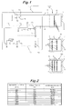
- Fig. 1 is a circuit diagram showing an example of a lighting apparatus according to the present invention
- Fig. 2 is a table showing a relation between appropriate current and identification resistance
- Fig. 3 is a circuit diagram showing another embodiment of the invention.
- each of lighting heads H 1 to H 3 in which one or more LEDs (light emitting device) 2, 2 --- are arranged in an optional intended pattern is connected with a power supply B.
- Each of the lighting heads H 1 to H 3 has a lighting circuit 6 for connecting one or more LEDs (light emitting devices) 2, 2 --- to a power supply circuit 5 connected with power supply terminals 3, 4 of a power supply B, and an identification circuit 7 outputs a current identification signals in accordance with an appropriate current of the lighting circuit 6, the light circuit 6 and the identification circuit 7 being connected in parallel with each other.
- the number and the way of connection of LEDs 2, 2 --- connected in the lighting circuit 6 are different on every lighting heads H 1 to H 3 . That is, LED 2, 2 --- with a rated forward current of 20 mA are connected in series by the number of six in the lighting head H 1 , LED 2, 2 --- connected in series by the number of six are further connected in parallel by two rows in the lighting head H 2 , and LED 2, 2 --- connected in series by the number of six are further connected in parallel by three rows in the lighting head H 2 . Accordingly, the appropriate current for the respective lighting circuits 6 is 20 mA for the lighting head H 1 , 40 mA for the lighting head H 2 and 60 mA for the lighting head H 3 . Further, an identification resistor 8 set to a resistance value of 52.8 to 3.3 k ⁇ is interposed in the identification circuit 7 in accordance with the appropriate current, for example, from 20 to 200 mA as shown in Fig. 2.
- the lighting voltage Vf per one red LED 2 is about 1.8 V
- the lower limit voltage VLmin for lighting is about 11 V
- the lighting circuit 6 is rendered conductive to light-up LEDs 2, 2 --- when the voltage applied from the power supply B to the power supply circuit 5 is 11 V or higher. Further, when LEDs 2, 2 --- are lit and the lighting circuit 6 is short-circuited, the identification circuit 7 is rendered non-conductive.
- a driving power supply 11 that supplies a lighting voltage VL at or higher than the lower limit voltage VLmin for lighting (for example, 12 V) during a lighting-up state of LEDs 2, 2 ---- and an identification power supply 12 that supplies an identification voltage VM (for example, 2.5 V) which is lower than the lower limit voltage VLmin for lighting-up the lighting circuit 6 during a not lighting-up state of LEDs 2,2 --- are connected being in parallel with each other to the positive power terminal 3.
- a current setter 13 that sets an appropriate current I R to be supplied to the lighting circuit 6 based on the current identification signal outputted from the identification circuit 7 of the lighting head H 1 - H 3 and a lighting current control circuit 14 that maintains the appropriate current I R supplied to the lighting circuit 6 during the lighting-up state of the LEDs 2, 2 --- in accordance with the current setting signal outputted from the current setter 13 are connected being in parallel with each other to the power terminal 4 on the ground side.
- a switch S 1 is interposed between the driving power supply 11 and the terminal 3.
- the switch S 1 turns OFF in synchronization with a vertical synchronization signal of a video camera that is outputted, for example, on every 1/60 sec and remains ON in other state than described above, thereby lighting-up LEDs 2, 2 --- during picking-up of 1 frame images.
- a diode 15 is interposed between the identification power supply 12 and the terminal 3 for inhibiting the supply of the identification voltage VM from the identification power supply 12 during the ON-period of the driving power supply 11.
- an identification signal detection resistor 16 for example, of 2.2 k ⁇ is grounded to the earth.
- the current flowing through the identification resistor 8 in each of the lighting heads H 1 to H 3 is supplied to the detection resistor 16, it causes voltage drop in the detection resistor 16.
- An appropriate current I R to be supplied to the lighting circuit 6 is set in accordance with the current identification signal based on the detected amount of the voltage drop. For example, in a case where the identification resistor 8 for each of the lighting heads H 1 to H 3 is selected for the identification voltage VM at 2.5 V supplied from the identification power supply 12, as shown in Fig. 2, the amount of the voltage drop Vc across the detection resistor 16 of 2.2 k ⁇ can be changed each by 0.1 V from 0.1 V to 1.0 V. Accordingly, when the amount of the voltage drop is used for the current identification signal, ten levels of appropriate current can be distinguished.
- a holding capacitor 17, a buffer amplifier 18, etc. are provided for outputting a current setting signal from 20 mV to 200 mV corresponding to the setting value of 20 to 200 mA of the appropriate current I R for 1/60 sec in accordance with the image pick-up time for 1 frame based on the current identification signal at 0.1 to 1.0 V. Further, on the contrary to the switch S 1 , since switch S 3 turns ON in synchronization with the vertical synchronization signal of the video camera and remains OFF in other state than described above, it stores a current identification signal in the interval from picking-up one frame images till picking-up next frame images.
- the lighting current control circuit 14 controls the current flowing in the lighting circuit 6 in accordance with the current setting signal outputted from the current setter 13, in which a current detection resistor 21, for example, of 1 ⁇ is connected to the power supply terminal 4 on the ground side by way of an FET 20. Then, a control signal is applied from a comparative circuit 22 to the gate of the FET 20 by a switch S 2 which turns OFF in synchronization with the vertical synchronization signal of the video camera and turns ON in other state than described above, like the switch S 1 , so that the detection signal detected by the current detection resistor 21 is identical with the current setting signal outputted from the current setter 13 in a state where the power is supplied to the lighting circuit 6 and LEDs 2, 2 --- are in the lighting-up state.
- the identification resistor 8 at a resistance value of 52.8 k ⁇ , 25.3 k ⁇ , or 16.1 k ⁇ is interposed in the identification circuit 7 according to the table shown in Fig. 2.
- a current identification signal at 0.1 V (0.2 or 0.3 V) is outputted by the voltage drop caused in the identification resister in the light head H 1 (or H 2 or H 3 ) mounted to the power supply B, and the current is charged in the holding capacitor 17, and the current setting signal at 20 (40 or 60) mV corresponded to the setting value 20 (or 40, 60) mA of the appropriate current I R is continuously outputted for 1/60 sec to the lighting current control circuit 14.
- a detection signal at 20 mV + ⁇ is outputted from the current detection resistor 21 of 1 ⁇ , which is compared with the current setting signal at 20 mV outputted from the current setter 13 to output a control signal to the FET 20 such that the detection signal lowers to 20 mV, that is, the light current flowing in the light circuit 6 is 20 mA.
- a detection signal at 20 mV - ⁇ is outputted from the current detection resistor 21 of 1 ⁇ , which is compared with the current setting signal at 20 mV outputted from the current setter 13, and a control signal is outputted to the FET 20 such that the detection signal is increased up to 20 mV, that is, the light current flowing in the lighting circuit 6 is controlled to 20 mA.
- a control signal is outputted to the FET 20 such that the light current flowing in the lighting circuit 6 is 40 or 60 mA in the same manner.
- the current setter 13 may comprise an A/D converter 25 for converting a detection signal outputted from the identification signal detection resistor 16 into a digital signal, a micro-computer 27 for outputting a current setting signal according to an appropriate current with reference to a detection signal - appropriate current conversion table 26, and a D/A converter 28 for converting the current setting signal into an analog signal.
- the current flowing in the identification resistor 8 is supplied to the detection resistor 16 in the same manner as described above, to cause voltage drop in the detection resistor 16, and an appropriate current I R to be supplied to the lighting circuit 6 in accordance with the current identification signal is set by using the detected amount of voltage drop as the current identification signal.
- the identification voltage VM is 2.5 V
- the resistors value of the detection resistor 16 is 2.2 k ⁇
- the amount of voltage drop Vc is determined in accordance with the identification resistor 8.
- the detection signal - appropriate current conversion table 26 is determined corresponding to the identification resistor 8, for example, as shown in Fig. 4, and an identification resistor 8 of a resistance value in accordance with the appropriate current is attached to each of the lighting heads H 1 to H 3 .
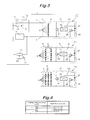
- Fig. 5 shows a further embodiment of a lighting apparatus according to the present invention in which those portions in common with Fig. 1 carry identical reference numerals for which detailed description will be omitted.
- a micro-computer 32 for encoding use that outputs a current identification signal formed by pulsating a current identification code different depending on the appropriate current of the light circuit 6 is connected in an identification circuit 31 of a lighting head H 1 (or H 2 , or H 3 ), and a current setter 33 comprises a micro-computer 35 for decoding use that reads a current identification code from the current identification signal and sets an appropriate current with reference to an identification code - appropriate current conversion table 34.
- a Zener diode 37 with a Zener voltage at 3 V is disposed to a switching circuit 36. Since the switching circuit 36 is rendered conductive when a voltage of 3 V or higher is applied by way of the power supply terminal 3 and 4 to turn the transistor 38 to on, a reset signal is inputted to the micro-computer 32 for encoding use to turn the micro-computer 32 to an OFF state. Further, when a voltage at 3 V or lower is applied, since the switching circuit 36 is rendered non-conductive, the current is supplied by way of the power supply circuit 39 to the micro-computer 32, and a transistor 40 turns ON and OFF by the pulse signal in accordance with a predetermined current identification code, and a pulsated current identification signal is outputted.
- the current identification signal inputted to a current setter 33 is inputted to a micro-computer 35 for decoding use, which reads a current identification code from the pulse signal to output a current setting signal with reference to the identification code - appropriate current conversion table 34.
- the identification code is not restricted only to the appropriate current so long as it corresponds to the appropriate current and, for example, it may be a model number for lighting heads (H 1 to H 3 ) such as H1234, H2468, and H3471. In this case, when appropriate currents corresponding to the model numbers are previously registered in the identification code - appropriate current conversion table 34, appropriate current corresponding to the light head H 1 to H 3 can be read out.
- a current identification signal is outputted in accordance with the appropriate current from the lighting head in a state while the light emitting devices in each of the lighting heads are not in the lighting-up state, and the current supply to the lighting circuit can be maintained at an appropriate current in accordance with the current identification signal. Accordingly, this can provide an excellent effect capable of lighting-up the individual light emitting devices connected in the lighting circuit at a rate current irrespective of the specification of the lighting heads.
- the current supplied from the current supply can automatically be kept at an appropriate current and the light emitting devices can always be in a lighting-up state at the rated current irrespective of the specification of the lighting head, it is suitable to the application use in which lighting heads of different appropriate currents can optionally be attached selectively to the power supply and used.
- the present disclosure relates to subject matter contained in priority Japanese Patent Application No. 2003-323,991 filed on September 17, 2003, the contents of which is herein expressly incorporated by reference in its entirety.
Landscapes
- Circuit Arrangement For Electric Light Sources In General (AREA)
- Printers Or Recording Devices Using Electromagnetic And Radiation Means (AREA)
Abstract
Description
- The present invention concerns a lighting method of connecting a lighting head having one or more light emitting devices arranged in an optional pattern to a power supply and lighting-up them, a lighting apparatus used for the method and components therefor.
- In a case of connecting a lighting head having a number of light emitting devices, for example, light-emitting diodes (hereinafter sometimes referred to as LEDs) to a power supply, the electric power for the power supply is set so as to supply an appropriate current for flowing a rated current for lighting to individual LEDs from the power supply to the lighting head.
- Recently, a power supply capable of controlling the current in accordance with the number of LEDs so that a rated current can be supplied to respective LEDs even in a case of connecting a lighting head capable of lighting individual LEDs respectively has been proposed (for example, refer to Patent Document 1: JP-A No. 2000-6466).
- However, the power supply described above is adapted to control the current in accordance with the number of LEDs to be lit in a case of connecting a specified lighting head.
In a case of using lighting heads of different specifications, the power supply can not control the current in accordance with specifications. - That is, lighting heads using lighting devices such as LEDs include versatile types and specifications such as connection methods of LEDs to the power supply circuit (for example, parallel or serial connection), quantity of LEDs used, and ratings of individual LEDs are different on every lighting heads, so that power supplies or current controllers have to be designed and manufactured in accordance with the lighting heads.
- For example, as shown in Fig. 7, in a case where the rated current of
individual LEDs 72 attached to alighting head 71 is specified as 20 mA, it is necessary to supply a current to apower supply circuit 73 at a level of 20 mA, when sixLEDs LEDs LEDs
In this case, since the resistance characteristic ofLEDs - Accordingly, the power supply has been designed so far such that rated current can be supplied in accordance with the specification of each
lighting head 71 and, while current control can be conducted according to the number of LEDs to be lit within a predetermined specification, no appropriate current control can be done for lighting heads of other different specifications.
Accordingly, in a case where a power supply of an identical rating can be used irrespective of different specifications oflighting heads 71, this can greatly save the trouble of designing and manufacturing power supplies and conducting stock control on everyindividual lighting heads 71 and greatly decrease the manufacturing cost and save the troubles of stock control. - In view of the above, the present invention intends to solve the technical subject of lighting individual light emitting devices of a lighting head connected with a power supply each at a rated current by using a power supplying of one identical rating irrespective of different specifications of respective lighting heads.
- The foregoing subject can be attained in accordance with the present invention by a lighting method of connecting a lighting head having one or more light emitting elements arranged in an optional intended pattern to a power supply for lighting, which comprises outputting a current identification signal from the lighting head in accordance with an appropriate current determined by the arrangement of the light emitting devices during non lighting-up state of the light emitting devices and setting an appropriate current to be supplied to a lighting circuit based on an appropriate current identification signal and keeping the current flowing to the lighting circuit to an appropriate level by a lighting current control circuit during a lighting-up state of the light emitting devices.
- The method of the present invention described above can be conducted by a lighting apparatus in accordance with the invention comprising;
a lighting head having
a lighting circuit that supplies a current to light emitting devices when an application voltage is at or higher than a lower limit voltage for lighting determined by the arrangement of the light emitting devices, and
an identification circuit that outputs a current identification signal in accordance with an appropriate current for the lighting circuit in a case when the application voltage is lower than the lower limit voltage for lighting, and
a power supply having a driving power supply that applies a lighting voltage at or higher than the lower limit voltage for lighting to the lighting circuit during a lighting-up state of the light emitting devices,
an identification power supply that applies an identification voltage lower than the lower limit voltage for lighting to the identification circuit during a non lighting-up state of the light emitting devices,
a current setter that sets an appropriate current to be supplied to the lighting circuit based on the current identification signal outputted from the identification circuit, and
a lighting current control circuit that keeps the current flowing to the lighting circuit during a lighting-up state of the light emitting devices to an appropriate current in accordance with the current setting signal outputted from the current setter. - According to the lighting method of the present invention, the appropriate current identification signal in accordance with the appropriate current determined by the arrangement of the light emitting devices in the lighting head is outputted in the non lighting-up state of the light emitting devices, and the value of the current to be supplied to the lighting head can be recognized based on the identification signal.
This can maintain the current supplied from the power supply to the lighting circuit during the lighting-up state of the light emitting devices to the appropriate current by the lighting current control circuit to light-up the individual light emitting devices at a rated current irrespective of the specification of the lighting head. - In this case, by the provision of the lighting circuit that supplies current to the light emitting devices when the application voltage is at or higher than the lower limit for lighting determined by the arrangement of the light emitting devices and the current identification circuit that outputs the current identification signal in accordance with the appropriate current for the lighting circuit when the application voltage is lower than the lower limit for lighting, the identification circuit operates during non lighting-up state of the light emitting devices in accordance with the voltage supplied from the power supply to output the current identification signal.
The identification circuit can be constituted, for example, by using an identification resistor having a different resistance value depending on the appropriate current or by using a micro-computer for encoding that outputs a current identification signal obtained by pulsating a current identification code which is different depending on the appropriate current. - Then, when a current identification signal is outputted from the identification circuit, an appropriate current to be supplied to the lighting circuit is set by the current setter.
In a case where an identification resistor is interposed in the identification circuit, the current setter is adapted to output a current setting signal in accordance with the current flowing through the identification resistor.
Further, in a case of using a micro-computer for encoding use in the identification circuit, the current setter reads a current identification code as the current identification signal by the micro-computer and sets an appropriate current with reference to an identification code-appropriate current conversion table.
Accordingly, this can provide an effect capable of maintaining the current supplied from the power supply to the lighting circuit to an appropriate current by the lighting current control circuit during the lighting state of the light emitting devices and capable of lighting-up individual lighting devices each at a rated current irrespective of the specification of the lighting head. - Preferred embodiments of the present invention will be described in details based on the drawings, wherein
- Fig. 1 is a circuit diagram showing an example of a lighting apparatus according to the present invention;
- Fig. 2 is a table showing a relation between appropriate current and identification resistance;
- Fig. 3 is a circuit diagram showing another embodiment of the invention;
- Fig. 4 is a table showing a relation between appropriate current and identification resistance;
- Fig. 5 is a circuit diagram showing a further embodiment of the invention;
- Fig. 6 is a table showing a relation between appropriate current and identification code; and
- Fig. 7(a) is an explanatory view showing an existent lighting head with LEDs connected in series, Fig. 7(b) is showing an existent lighting head with LEDs connected in parallel by two rows, Fig. 7(c) is showing an existent lighting head with LEDs connected in parallel by three rows.
-
- The purpose of lighting-up individual light emitting devices connected to a lighting circuit each at a rated current irrespective of the specification of a lighting head has been attained by outputting a current identification signal in accordance with an appropriate current from the lighting head during non lighting-up state of light emitting devices.
- Fig. 1 is a circuit diagram showing an example of a lighting apparatus according to the present invention, Fig. 2 is a table showing a relation between appropriate current and identification resistance, and Fig. 3 is a circuit diagram showing another embodiment of the invention.
- In a
lighting apparatus 1 shown in Fig. 1, each of lighting heads H1 to H3 in which one or more LEDs (light emitting device) 2, 2 --- are arranged in an optional intended pattern is connected with a power supply B.
Each of the lighting heads H1 to H3 has alighting circuit 6 for connecting one or more LEDs (light emitting devices) 2, 2 --- to apower supply circuit 5 connected withpower supply terminals identification circuit 7 outputs a current identification signals in accordance with an appropriate current of thelighting circuit 6, thelight circuit 6 and theidentification circuit 7 being connected in parallel with each other. - The number and the way of connection of
LEDs lighting circuit 6 are different on every lighting heads H1 to H3. That is,LED LED LED
Accordingly, the appropriate current for therespective lighting circuits 6 is 20 mA for the lighting head H1, 40 mA for the lighting head H2 and 60 mA for the lighting head H3. Further, anidentification resistor 8 set to a resistance value of 52.8 to 3.3 kΩ is interposed in theidentification circuit 7 in accordance with the appropriate current, for example, from 20 to 200 mA as shown in Fig. 2. - Since the lighting voltage Vf per one
red LED 2 is about 1.8 V, in a case where theLED lighting circuit 6 is rendered conductive to light-upLEDs power supply circuit 5 is 11 V or higher. Further, whenLEDs lighting circuit 6 is short-circuited, theidentification circuit 7 is rendered non-conductive. When the voltage applied from the power supply B to thepower supply circuit 5 decreases to 10 V or lower which is lower than the lower limit voltage VLmin for lighting to render thelighting circuit 6 non-conductive, sinceLEDs identification circuit 7 is rendered conductive, and a current identification signal is outputted in accordance with the resistance value of theidentification resistor 8.
As described above, since thelight circuit 6 and theidentification circuit 7 are connected being in parallel with each other and connected to thepower supply circuit 5 and their operation voltages are different, thecircuits terminals - In the power supply B, a
driving power supply 11 that supplies a lighting voltage VL at or higher than the lower limit voltage VLmin for lighting (for example, 12 V) during a lighting-up state ofLEDs identification power supply 12 that supplies an identification voltage VM (for example, 2.5 V) which is lower than the lower limit voltage VLmin for lighting-up thelighting circuit 6 during a not lighting-up state ofLEDs positive power terminal 3.
Acurrent setter 13 that sets an appropriate current IR to be supplied to thelighting circuit 6 based on the current identification signal outputted from theidentification circuit 7 of the lighting head H1 - H3 and a lightingcurrent control circuit 14 that maintains the appropriate current IR supplied to thelighting circuit 6 during the lighting-up state of theLEDs current setter 13 are connected being in parallel with each other to thepower terminal 4 on the ground side. - A switch S1 is interposed between the
driving power supply 11 and theterminal 3. The switch S1 turns OFF in synchronization with a vertical synchronization signal of a video camera that is outputted, for example, on every 1/60 sec and remains ON in other state than described above, thereby lighting-upLEDs
Adiode 15 is interposed between theidentification power supply 12 and theterminal 3 for inhibiting the supply of the identification voltage VM from theidentification power supply 12 during the ON-period of thedriving power supply 11. - In the
current setter 13, an identificationsignal detection resistor 16, for example, of 2.2 kΩ is grounded to the earth. When the current flowing through theidentification resistor 8 in each of the lighting heads H1 to H3 is supplied to thedetection resistor 16, it causes voltage drop in thedetection resistor 16. An appropriate current IR to be supplied to thelighting circuit 6 is set in accordance with the current identification signal based on the detected amount of the voltage drop.
For example, in a case where theidentification resistor 8 for each of the lighting heads H1 to H3 is selected for the identification voltage VM at 2.5 V supplied from theidentification power supply 12, as shown in Fig. 2, the amount of the voltage drop Vc across thedetection resistor 16 of 2.2 kΩ can be changed each by 0.1 V from 0.1 V to 1.0 V.
Accordingly, when the amount of the voltage drop is used for the current identification signal, ten levels of appropriate current can be distinguished. - A
holding capacitor 17, abuffer amplifier 18, etc. are provided for outputting a current setting signal from 20 mV to 200 mV corresponding to the setting value of 20 to 200 mA of the appropriate current IR for 1/60 sec in accordance with the image pick-up time for 1 frame based on the current identification signal at 0.1 to 1.0 V.
Further, on the contrary to the switch S1, since switch S3 turns ON in synchronization with the vertical synchronization signal of the video camera and remains OFF in other state than described above, it stores a current identification signal in the interval from picking-up one frame images till picking-up next frame images. - The lighting
current control circuit 14 controls the current flowing in thelighting circuit 6 in accordance with the current setting signal outputted from thecurrent setter 13, in which acurrent detection resistor 21, for example, of 1 Ω is connected to thepower supply terminal 4 on the ground side by way of anFET 20.
Then, a control signal is applied from acomparative circuit 22 to the gate of theFET 20 by a switch S2 which turns OFF in synchronization with the vertical synchronization signal of the video camera and turns ON in other state than described above, like the switch S1, so that the detection signal detected by thecurrent detection resistor 21 is identical with the current setting signal outputted from thecurrent setter 13 in a state where the power is supplied to thelighting circuit 6 andLEDs
Accordingly, when an appropriate current at 20 mA, 40 mA or 60 mA is supplied to thelighting circuit 6 for each of the lighting heads H1 to H3, a detection signal at 20 mV, 40 mV or 60 mV is outputted by the voltage drop caused in thecurrent detection resistor 21 which is inputted to thecomparison circuit 22. - The operation of the constitution described above will be explained below.
In accordance with the appropriate current 20 mA, 40 mA, or 60 mA in thelighting circuit 6 for each of the lighting heads H1 to H3, theidentification resistor 8 at a resistance value of 52.8 kΩ, 25.3 kΩ, or 16.1 kΩ is interposed in theidentification circuit 7 according to the table shown in Fig. 2.
Then, when a desired lighting head H1 (or H2 or H3) is connected with the power supply B and each of the switches S1 to S3 is turned on and off being synchronized with the vertical synchronization signal of the video camera, the switch S1 turns OFF before picking-up of one frame images, and an identification voltage VM at 2.5 V is supplied from theidentification power supply 12 to one light head H1 (or H2 or H3). - In this case, since six
LEDs power source terminals lighting circuit 6 of each lighting head H1 (or H2 or H3), the lower limit voltage VLmin for lighting for them is 11 V and thelighting circuit 6 is kept in a non-conductive state even when an identification voltage at 2.5 V is applied.
Further, in synchronization with the switch S1, since the lightcurrent control circuit 14 is also rendered non-conductive by the switch S2, the current flows through theidentification circuit 7 of the lighting head H1 (or H2 or H3) to thecurrent setter 13 of the power supply B. - From the identification
signal detection resistor 16 of thecurrent setter 13, a current identification signal at 0.1 V (0.2 or 0.3 V) is outputted by the voltage drop caused in the identification resister in the light head H1 (or H2 or H3) mounted to the power supply B, and the current is charged in the holdingcapacitor 17, and the current setting signal at 20 (40 or 60) mV corresponded to the setting value 20 (or 40, 60) mA of the appropriate current IR is continuously outputted for 1/60 sec to the lightingcurrent control circuit 14. - Then, at the same time with the starting of picking-up one frame images, switches S1 and S3 turn ON and when a lighting voltage VL = 12 V is supplied from the driving
power supply 11, since the lighting voltage VL > lower limit voltage VLmin for lighting, thelighting circuit 6 turns ON and most of the current flows in thelighting circuit 6 and the current to theidentification circuit 7 is substantially negligible. - In this case, when the current flowing in the
lighting circuit 6 is higher than the appropriate current of 20 mA, a detection signal at 20 mV + α is outputted from thecurrent detection resistor 21 of 1 Ω, which is compared with the current setting signal at 20 mV outputted from thecurrent setter 13 to output a control signal to theFET 20 such that the detection signal lowers to 20 mV, that is, the light current flowing in thelight circuit 6 is 20 mA.
In the same manner, if it is controlled to lower than the appropriate current of 20 mA, a detection signal at 20 mV - α is outputted from thecurrent detection resistor 21 of 1 Ω, which is compared with the current setting signal at 20 mV outputted from thecurrent setter 13, and a control signal is outputted to theFET 20 such that the detection signal is increased up to 20 mV, that is, the light current flowing in thelighting circuit 6 is controlled to 20 mA.
In a case where the lighting head H2 or H3 is connected, since the current setting signal at 40 or 60 mV is outputted from thecurrent setter 13, a control signal is outputted to theFET 20 such that the light current flowing in thelighting circuit 6 is 40 or 60 mA in the same manner. - When it is intended that the detection signal outputted from the identification
signal detection resistor 16 is in proportion with the appropriate current, since theidentification resistor 8 has to be decreased substantially in an inverse proportion therewith, this restricts the selection range for theidentification resistor 8.
Then, As shown in Fig. 3, thecurrent setter 13 may comprise an A/D converter 25 for converting a detection signal outputted from the identificationsignal detection resistor 16 into a digital signal, a micro-computer 27 for outputting a current setting signal according to an appropriate current with reference to a detection signal - appropriate current conversion table 26, and a D/A converter 28 for converting the current setting signal into an analog signal.
Then, the current flowing in theidentification resistor 8 is supplied to thedetection resistor 16 in the same manner as described above, to cause voltage drop in thedetection resistor 16, and an appropriate current IR to be supplied to thelighting circuit 6 in accordance with the current identification signal is set by using the detected amount of voltage drop as the current identification signal.
In a case where the identification voltage VM is 2.5 V, and the resistors value of thedetection resistor 16 is 2.2 kΩ, the amount of voltage drop Vc is determined in accordance with theidentification resistor 8.
Accordingly, the detection signal - appropriate current conversion table 26 is determined corresponding to theidentification resistor 8, for example, as shown in Fig. 4, and anidentification resistor 8 of a resistance value in accordance with the appropriate current is attached to each of the lighting heads H1 to H3. - Fig. 5 shows a further embodiment of a lighting apparatus according to the present invention in which those portions in common with Fig. 1 carry identical reference numerals for which detailed description will be omitted.
In this embodiment, a micro-computer 32 for encoding use that outputs a current identification signal formed by pulsating a current identification code different depending on the appropriate current of thelight circuit 6 is connected in anidentification circuit 31 of a lighting head H1 (or H2, or H3), and acurrent setter 33 comprises a micro-computer 35 for decoding use that reads a current identification code from the current identification signal and sets an appropriate current with reference to an identification code - appropriate current conversion table 34. - In the
identification circuit 31, aZener diode 37 with a Zener voltage at 3 V is disposed to aswitching circuit 36. Since the switchingcircuit 36 is rendered conductive when a voltage of 3 V or higher is applied by way of thepower supply terminal transistor 38 to on, a reset signal is inputted to the micro-computer 32 for encoding use to turn the micro-computer 32 to an OFF state.
Further, when a voltage at 3 V or lower is applied, since the switchingcircuit 36 is rendered non-conductive, the current is supplied by way of thepower supply circuit 39 to the micro-computer 32, and atransistor 40 turns ON and OFF by the pulse signal in accordance with a predetermined current identification code, and a pulsated current identification signal is outputted. - The current identification signal inputted to a
current setter 33 is inputted to a micro-computer 35 for decoding use, which reads a current identification code from the pulse signal to output a current setting signal with reference to the identification code - appropriate current conversion table 34.
The identification code is not restricted only to the appropriate current so long as it corresponds to the appropriate current and, for example, it may be a model number for lighting heads (H1 to H3) such as H1234, H2468, and H3471.
In this case, when appropriate currents corresponding to the model numbers are previously registered in the identification code - appropriate current conversion table 34, appropriate current corresponding to the light head H1 to H3 can be read out. - As has been described above, according to the invention, a current identification signal is outputted in accordance with the appropriate current from the lighting head in a state while the light emitting devices in each of the lighting heads are not in the lighting-up state, and the current supply to the lighting circuit can be maintained at an appropriate current in accordance with the current identification signal. Accordingly, this can provide an excellent effect capable of lighting-up the individual light emitting devices connected in the lighting circuit at a rate current irrespective of the specification of the lighting heads.
- In accordance with the present invention, since the current supplied from the current supply can automatically be kept at an appropriate current and the light emitting devices can always be in a lighting-up state at the rated current irrespective of the specification of the lighting head, it is suitable to the application use in which lighting heads of different appropriate currents can optionally be attached selectively to the power supply and used.
The present disclosure relates to subject matter contained in priority Japanese Patent Application No. 2003-323,991 filed on September 17, 2003, the contents of which is herein expressly incorporated by reference in its entirety.
Claims (8)
- A lighting method of connecting lighting heads each having a lighting circuit in which one or more light emitting devices are connected in any optional arrangement to a power supply and lighting-up them, wherein the method comprises;
outputting a current identification signal in accordance with an appropriate current of a lighting circuit determined by the arrangement of the light emitting devices from a lighting head during a not lighting-up state of the light emitting devices, setting an appropriate current to be supplied to the lighting circuit based on the current identification signal, and maintaining the current flowing in the light circuit during a lighting-up state of the light emission devices to an appropriate current by a control circuit. - A lighting apparatus in which lighting heads each having one or more of light emitting devices arranged in any optional pattern is connected to a power supply in use, wherein
the lighting head comprises a lighting circuit for supplying a current to the light emitting devices when an application voltage is at or higher than a lower limit voltage for lighting which is determined based on the arrangement of the light emitting devices and an identification circuit that outputs a current identification signal in accordance with an appropriate current for the lighting circuit when the application voltage is lower than the lower limit voltage for lighting, and
the power supply comprises a driving power supply that applies a lighting voltage at or higher than the lower limit voltage for lighting to the lighting circuit during a lighting-up state of the light emitting devices,
an identification power supply that applies an identification voltage lower than the lower limit voltage for lighting to the identification circuit during a not lighting-up state of the light emitting devices,
a current setter that sets an appropriate current to be supplied to the lighting circuit based on the current identification signal outputted from the identification circuit, and
a lighting current control circuit that maintains an appropriate current flowing to the lighting circuit during the lighting-up state of the light emitting devices in accordance with the current setting signal outputted from the current setter. - A lighting apparatus according to claim 2, wherein the lighting circuit and the identification circuit in the lighting head are connected being in parallel with each other to the power supply circuit to be connected with the power supply terminals of the power supply.
- A lighting apparatus according to claim 2 or 3, wherein an identification resistor having a resistance value different depending on the appropriate current for the lighting circuit is interposed in the identification circuit and the current setter outputs a current setting signal in accordance with the current flowing through the identification resistor.
- A lighting apparatus according to any one of claims 2 to 4, wherein the current setter comprises a micro-computer that sets an appropriate current based on the identification data read from the current identification signal with reference to an identification data - appropriate current conversion table.
- A lighting apparatus according to claim 2 or 3, wherein the identification circuit comprises a micro-computer for encoding use that outputs a current identification signal formed by pulsating a current identification code which is different depending on the appropriate current for the lighting circuit, and the current setter comprises a micro-computer for decoding use that reads a current identification code from the current identification signal and sets an appropriate current with reference to the identification code - appropriate current conversion table.
- A lighting head having one or more of light emitting devices arranged therein and connected with a power supply in use, comprising;
a lighting circuit which is rendered conducting when an application voltage is at or higher than the lower limit voltage for lighting determined by the arrangement of the light emitting devices and supplies a current to the light emitting devices, and
an identification circuit which is rendered conductive when the application voltage lowers to a voltage lower than the lower limit voltage for lighting and outputs a current identification signal in accordance with the appropriate current for the lighting circuit. - A power supply used in connection with a lighting head having one or more of light emitting devices arranged therein comprising a lighting circuit that supplies a current to the light emitting devices when an application voltage is at or higher than the lower limit voltage for lighting determined by the arrangement of the light emitting devices and
an identification circuit that outputs a current identification signal in accordance with the appropriate current for the lighting circuit when the application voltage is lower than the lower limit voltage for lighting, wherein the power supply comprises;
a driving power source that applies a lighting voltage at or higher than the lower limit voltage for lighting during a lighting-up state of the light emitting devices, an identification power supply that applies an identification voltage lower than the lower limit voltage for lighting to the identification circuit during a not lighting-up state of the light emitting devices, a current setter that sets an appropriate current to be supplied to the lighting circuit based on the current identification signal outputted from the identification circuit, and a lighting current control circuit that maintains the current flowing in the lighting circuit in the lighting-up state of the light emitting devices to an appropriate current in accordance with the current setting signal outputted from the current setter.
Applications Claiming Priority (2)
| Application Number | Priority Date | Filing Date | Title |
|---|---|---|---|
| JP2003323991A JP2005093196A (en) | 2003-09-17 | 2003-09-17 | Illumination method, illumination device and parts thereof |
| JP2003323991 | 2003-09-17 |
Publications (1)
| Publication Number | Publication Date |
|---|---|
| EP1517588A1 true EP1517588A1 (en) | 2005-03-23 |
Family
ID=34191295
Family Applications (1)
| Application Number | Title | Priority Date | Filing Date |
|---|---|---|---|
| EP04021766A Withdrawn EP1517588A1 (en) | 2003-09-17 | 2004-09-14 | Method and apparatus for connecting a headlamp |
Country Status (3)
| Country | Link |
|---|---|
| US (1) | US7259522B2 (en) |
| EP (1) | EP1517588A1 (en) |
| JP (1) | JP2005093196A (en) |
Cited By (21)
| Publication number | Priority date | Publication date | Assignee | Title |
|---|---|---|---|---|
| DE102007009104A1 (en) * | 2007-02-24 | 2008-08-28 | Lear Corporation Gmbh | Control circuit for clocked driving at least one light emitting diode |
| DE102007049052A1 (en) * | 2007-10-11 | 2009-04-23 | Reiner Retkowski | Light producing device, has converting device provided for automatically converting electrical energy according to received information, so that electrical energy supplied to counter-connection devices includes electrical parameter |
| EP2154933A1 (en) * | 2008-08-14 | 2010-02-17 | Goodrich Lighting Systems GmbH | LED reading light and method for operating an LED reading light |
| DE102008039530A1 (en) * | 2008-08-23 | 2010-02-25 | Hella Kgaa Hueck & Co. | Diode assembly i.e. LED, temperature detecting device, has measuring device connected with connecting terminals, where measuring device has resistor with temperature dependent resistance value indicating temperature of diode assembly |
| WO2011067177A1 (en) * | 2009-12-04 | 2011-06-09 | Osram Gesellschaft mit beschränkter Haftung | A method for controlling the operation of an electronic converter, and a corresponding electronic converter, lighting system and software product |
| EP2387290A1 (en) * | 2010-05-12 | 2011-11-16 | Valeo Vision | Method for controlling the power supply of LED units |
| WO2014001360A1 (en) * | 2012-06-25 | 2014-01-03 | Osram Gmbh | Lighting system with an interface having a power supply unit and at least one light source module |
| US8710750B2 (en) | 2011-01-21 | 2014-04-29 | Mitsubishi Electric Corporation | Light source lighting device including a constant-current supply that is connected to a light source and supplies a constant current of a substantially constant magnitude to the light source, and luminaire |
| DE102012224141A1 (en) * | 2012-12-21 | 2014-06-26 | Tridonic Gmbh & Co Kg | LED module for LED lamp, has LED circuit that is turned on and light is emitted with connection of LED path, when active power load is not applied to LED circuit |
| DE102013001194A1 (en) * | 2013-01-24 | 2014-07-24 | Jakob Löschke | LED module for use in LED lightening system, has power supplies for applying voltage and/or current, where one of power supplies is used for bidirectional signal transmission from module to module circuitry |
| EP2814302A1 (en) * | 2013-06-10 | 2014-12-17 | OSRAM GmbH | Lighting module and corresponding lighting system |
| WO2014094016A3 (en) * | 2012-12-21 | 2014-12-18 | Tridonic Gmbh & Co Kg | Detection of an led module |
| WO2015077811A1 (en) * | 2013-11-28 | 2015-06-04 | Tridonic Gmbh & Co Kg | Led module |
| WO2015077809A1 (en) * | 2013-11-28 | 2015-06-04 | Tridonic Gmbh & Co Kg | Detection method and detection device for an led module |
| WO2015077812A3 (en) * | 2013-11-28 | 2015-07-30 | Tridonic Gmbh & Co Kg | Led module |
| US9290055B2 (en) | 2009-12-03 | 2016-03-22 | Compagnie Generale Des Etablissements Michelin | Tire comprising a carcass reinforcement having cables and capillary tubes |
| WO2015168719A3 (en) * | 2014-05-09 | 2016-03-24 | Tridonic Gmbh & Co Kg | Operating device, lamp, and method for supplying an led module, with automatic recognition of the type of led module |
| EP2605620B1 (en) * | 2011-12-16 | 2016-07-13 | Samsung Electro-Mechanics Co., Ltd. | LED driving apparatus and method of driving LED |
| AT14906U1 (en) * | 2013-11-28 | 2016-08-15 | Tridonic Gmbh & Co Kg | LED module |
| DE102019127697B4 (en) | 2018-10-31 | 2023-11-30 | Tridonic Gmbh & Co Kg | Control module for a lamp operating device with a flexible control connection |
| DE102006020040B4 (en) | 2006-04-26 | 2024-05-16 | Continental Automotive Technologies GmbH | Marking method for motor vehicle control units, electro-hydraulic pressure control unit for motor vehicles and use of the method in a motor vehicle brake control system |
Families Citing this family (31)
| Publication number | Priority date | Publication date | Assignee | Title |
|---|---|---|---|---|
| TWI479466B (en) * | 2005-05-25 | 2015-04-01 | Koninkl Philips Electronics Nv | Flux compensation led driver system and method |
| JP2006351484A (en) * | 2005-06-20 | 2006-12-28 | Moritex Corp | Lighting device and lighting head used in the lighting device |
| JP2007042533A (en) * | 2005-08-05 | 2007-02-15 | Moritex Corp | Lighting device and lighting head used therefor |
| JP4988192B2 (en) * | 2005-12-12 | 2012-08-01 | 株式会社モリテックス | Lighting device and lighting head used in the lighting device |
| JP4457312B2 (en) * | 2006-01-12 | 2010-04-28 | 株式会社デンソー | Vehicle headlamp device |
| US7915570B2 (en) | 2007-08-03 | 2011-03-29 | National Instruments Corporation | Smart camera with an integrated lighting controller |
| JP2009111035A (en) * | 2007-10-26 | 2009-05-21 | Panasonic Electric Works Co Ltd | Light emitting diode driving device, lighting device using light emitting diode driving device, vehicle interior lighting device, vehicle lighting device |
| US8325225B2 (en) * | 2009-03-16 | 2012-12-04 | PT Papertech, Inc | Method and apparatus for a web inspection system |
| JP5436169B2 (en) * | 2009-11-27 | 2014-03-05 | 三菱電機株式会社 | Light source device |
| JP5414578B2 (en) * | 2010-03-12 | 2014-02-12 | 三菱電機株式会社 | Lighting device and lighting apparatus |
| JP5701090B2 (en) * | 2011-02-10 | 2015-04-15 | 三菱電機株式会社 | Light source module, lighting device and lighting system |
| JP5834237B2 (en) * | 2011-06-15 | 2015-12-16 | パナソニックIpマネジメント株式会社 | Lighting device |
| JP2013004370A (en) * | 2011-06-17 | 2013-01-07 | Sharp Corp | Illuminating device |
| DE102011087658A1 (en) * | 2011-12-02 | 2013-06-06 | Osram Gmbh | Parallel connected light chains |
| JPWO2013114618A1 (en) * | 2012-02-03 | 2015-05-11 | パイオニア株式会社 | Light emitting device, organic EL light emitting panel, and lighting drive device |
| WO2013114618A1 (en) * | 2012-02-03 | 2013-08-08 | パイオニア株式会社 | Light-emitting apparatus, organic el light-emitting panel, and lighting driver device |
| EP2645815A1 (en) | 2012-03-27 | 2013-10-02 | Koninklijke Philips N.V. | LED lighting system |
| JP6198812B2 (en) * | 2012-04-05 | 2017-09-20 | フィリップス ライティング ホールディング ビー ヴィ | LED lighting system |
| JP2013254566A (en) * | 2012-06-05 | 2013-12-19 | Mitsubishi Electric Corp | Light source lighting device and lighting apparatus |
| WO2015028511A1 (en) * | 2013-08-28 | 2015-03-05 | Elmos Semiconductor Ag | Apparatus for supplying at least one consumer with electrical energy or for providing electrical power for at least one consumer |
| JP6278350B2 (en) * | 2014-01-14 | 2018-02-14 | アール・ビー・コントロールズ株式会社 | LED lighting device |
| JP6206814B2 (en) * | 2014-02-28 | 2017-10-04 | パナソニックIpマネジメント株式会社 | Lighting device and lighting system using the lighting device |
| JP6372776B2 (en) | 2014-03-07 | 2018-08-15 | パナソニックIpマネジメント株式会社 | Light source device, lighting device, lighting fixture |
| JP6635701B2 (en) | 2015-07-29 | 2020-01-29 | シーシーエス株式会社 | LED lighting system, LED lighting device, and brightness adjustment method for LED lighting device |
| US20170086282A1 (en) * | 2015-09-17 | 2017-03-23 | UltraLED Inc. | Led lamp for a vehicle and testing method therefor |
| JP2017135225A (en) | 2016-01-27 | 2017-08-03 | シーシーエス株式会社 | Power supply device for use in led light-emitting device |
| DE102016220198B3 (en) | 2016-10-17 | 2018-02-15 | Continental Automotive Gmbh | Method for regulating an operating current of a lighting unit and control unit and motor vehicle |
| JP6293326B2 (en) * | 2017-03-08 | 2018-03-14 | 三菱電機照明株式会社 | LED lighting system |
| DE102018132077A1 (en) * | 2018-12-13 | 2020-06-18 | HELLA GmbH & Co. KGaA | Circuit arrangement and method for detecting a short circuit in a lighting unit |
| GB2613141A (en) * | 2021-10-01 | 2023-05-31 | Simmtronic Ltd | Lighting system |
| EP4721517A1 (en) * | 2023-05-24 | 2026-04-08 | Arkalumen Inc. | Lighting apparatus incorporating connectable control module and led module |
Citations (4)
| Publication number | Priority date | Publication date | Assignee | Title |
|---|---|---|---|---|
| EP0896899A2 (en) * | 1997-08-12 | 1999-02-17 | Reitter & Schefenacker GmbH & Co. KG | Vehicle lights |
| EP1244334A2 (en) * | 2001-03-22 | 2002-09-25 | Hella KG Hueck & Co. | Circuit for a LED light source |
| EP1246511A1 (en) * | 2001-03-28 | 2002-10-02 | Patent-Treuhand-Gesellschaft für elektrische Glühlampen mbH | Driver circuit for a LED-array |
| EP1411750A2 (en) * | 2002-10-16 | 2004-04-21 | CCS Inc. | Power supply system for light emitting diode unit |
Family Cites Families (9)
| Publication number | Priority date | Publication date | Assignee | Title |
|---|---|---|---|---|
| US5015921A (en) * | 1988-03-17 | 1991-05-14 | General Electric Company | Soft start solid state switch |
| US5144117A (en) * | 1990-02-27 | 1992-09-01 | Alps Electric Co., Ltd. | Illumination type optical recorded information reading device |
| JP3418673B2 (en) * | 1998-02-12 | 2003-06-23 | 株式会社日立製作所 | Control device for vehicle charging generator |
| JP2000006466A (en) | 1998-06-23 | 2000-01-11 | Canon Inc | LED power supply device and LED power supply control method |
| US6983212B2 (en) * | 2001-11-27 | 2006-01-03 | American Power Conversion Corporation | Battery management system and method |
| JP2003249383A (en) * | 2002-02-25 | 2003-09-05 | Patoraito:Kk | Failure diagnosis circuit for LED indicator |
| JP4085801B2 (en) * | 2002-03-11 | 2008-05-14 | 株式会社デンソー | Discharge lamp device |
| JP2004009826A (en) * | 2002-06-05 | 2004-01-15 | Koito Mfg Co Ltd | Lighting equipment for vehicles |
| US6836157B2 (en) * | 2003-05-09 | 2004-12-28 | Semtech Corporation | Method and apparatus for driving LEDs |
-
2003
- 2003-09-17 JP JP2003323991A patent/JP2005093196A/en active Pending
-
2004
- 2004-09-14 EP EP04021766A patent/EP1517588A1/en not_active Withdrawn
- 2004-09-15 US US10/941,101 patent/US7259522B2/en not_active Expired - Fee Related
Patent Citations (4)
| Publication number | Priority date | Publication date | Assignee | Title |
|---|---|---|---|---|
| EP0896899A2 (en) * | 1997-08-12 | 1999-02-17 | Reitter & Schefenacker GmbH & Co. KG | Vehicle lights |
| EP1244334A2 (en) * | 2001-03-22 | 2002-09-25 | Hella KG Hueck & Co. | Circuit for a LED light source |
| EP1246511A1 (en) * | 2001-03-28 | 2002-10-02 | Patent-Treuhand-Gesellschaft für elektrische Glühlampen mbH | Driver circuit for a LED-array |
| EP1411750A2 (en) * | 2002-10-16 | 2004-04-21 | CCS Inc. | Power supply system for light emitting diode unit |
Cited By (35)
| Publication number | Priority date | Publication date | Assignee | Title |
|---|---|---|---|---|
| DE102006020040B4 (en) | 2006-04-26 | 2024-05-16 | Continental Automotive Technologies GmbH | Marking method for motor vehicle control units, electro-hydraulic pressure control unit for motor vehicles and use of the method in a motor vehicle brake control system |
| DE102007009104B4 (en) * | 2007-02-24 | 2011-04-14 | Lear Corporation Gmbh | Control circuit for clocked driving at least one light emitting diode |
| DE102007009104A1 (en) * | 2007-02-24 | 2008-08-28 | Lear Corporation Gmbh | Control circuit for clocked driving at least one light emitting diode |
| DE102007049052A1 (en) * | 2007-10-11 | 2009-04-23 | Reiner Retkowski | Light producing device, has converting device provided for automatically converting electrical energy according to received information, so that electrical energy supplied to counter-connection devices includes electrical parameter |
| DE102007049052B4 (en) * | 2007-10-11 | 2009-09-03 | Reiner Retkowski | Device for generating light |
| EP2154933A1 (en) * | 2008-08-14 | 2010-02-17 | Goodrich Lighting Systems GmbH | LED reading light and method for operating an LED reading light |
| DE102008039530A1 (en) * | 2008-08-23 | 2010-02-25 | Hella Kgaa Hueck & Co. | Diode assembly i.e. LED, temperature detecting device, has measuring device connected with connecting terminals, where measuring device has resistor with temperature dependent resistance value indicating temperature of diode assembly |
| US9290055B2 (en) | 2009-12-03 | 2016-03-22 | Compagnie Generale Des Etablissements Michelin | Tire comprising a carcass reinforcement having cables and capillary tubes |
| CN102640568B (en) * | 2009-12-04 | 2014-08-13 | 欧司朗股份有限公司 | A method for controlling the operation of an electronic converter, and a corresponding electronic converter, lighting system and software product |
| WO2011067177A1 (en) * | 2009-12-04 | 2011-06-09 | Osram Gesellschaft mit beschränkter Haftung | A method for controlling the operation of an electronic converter, and a corresponding electronic converter, lighting system and software product |
| CN102640568A (en) * | 2009-12-04 | 2012-08-15 | 欧司朗股份有限公司 | A method for controlling the operation of an electronic converter, and a corresponding electronic converter, lighting system and software product |
| US8816603B2 (en) | 2009-12-04 | 2014-08-26 | Osram Gmbh | Method for controlling the operation of an electronic converter, and a corresponding electronic converter, lighting system and software product |
| FR2960119A1 (en) * | 2010-05-12 | 2011-11-18 | Valeo Vision | POWER SUPPLY CONTROL UNIT FOR LED SETS |
| EP2387290A1 (en) * | 2010-05-12 | 2011-11-16 | Valeo Vision | Method for controlling the power supply of LED units |
| US8698427B2 (en) | 2010-05-12 | 2014-04-15 | Valeo Vision | Module to control the supply to LED assemblies |
| US8710750B2 (en) | 2011-01-21 | 2014-04-29 | Mitsubishi Electric Corporation | Light source lighting device including a constant-current supply that is connected to a light source and supplies a constant current of a substantially constant magnitude to the light source, and luminaire |
| EP2605620B1 (en) * | 2011-12-16 | 2016-07-13 | Samsung Electro-Mechanics Co., Ltd. | LED driving apparatus and method of driving LED |
| US9445466B2 (en) | 2012-06-25 | 2016-09-13 | Osram Gmbh | Lighting system with an interface having a power supply unit and at least one light source module |
| WO2014001360A1 (en) * | 2012-06-25 | 2014-01-03 | Osram Gmbh | Lighting system with an interface having a power supply unit and at least one light source module |
| US9609700B2 (en) | 2012-06-25 | 2017-03-28 | Osram Gmbh | Light engine module, related power supply unit and lighting system |
| US9554430B2 (en) | 2012-06-25 | 2017-01-24 | Osram Gmbh | Lighting system with an interface having a power supply unit and at least one light source module |
| CN104885564A (en) * | 2012-12-21 | 2015-09-02 | 赤多尼科两合股份有限公司 | Detection of an LED module |
| DE102012224141A1 (en) * | 2012-12-21 | 2014-06-26 | Tridonic Gmbh & Co Kg | LED module for LED lamp, has LED circuit that is turned on and light is emitted with connection of LED path, when active power load is not applied to LED circuit |
| CN104885564B (en) * | 2012-12-21 | 2017-05-17 | 赤多尼科两合股份有限公司 | Detection of an LED module |
| WO2014094016A3 (en) * | 2012-12-21 | 2014-12-18 | Tridonic Gmbh & Co Kg | Detection of an led module |
| US9544970B2 (en) | 2012-12-21 | 2017-01-10 | Tridonic Gmbh & Co Kg | Detection of an LED module |
| DE102013001194A1 (en) * | 2013-01-24 | 2014-07-24 | Jakob Löschke | LED module for use in LED lightening system, has power supplies for applying voltage and/or current, where one of power supplies is used for bidirectional signal transmission from module to module circuitry |
| EP2814302A1 (en) * | 2013-06-10 | 2014-12-17 | OSRAM GmbH | Lighting module and corresponding lighting system |
| US9398658B2 (en) | 2013-06-10 | 2016-07-19 | Osram Gmbh | Lighting module and corresponding lighting system |
| AT14906U1 (en) * | 2013-11-28 | 2016-08-15 | Tridonic Gmbh & Co Kg | LED module |
| WO2015077809A1 (en) * | 2013-11-28 | 2015-06-04 | Tridonic Gmbh & Co Kg | Detection method and detection device for an led module |
| WO2015077811A1 (en) * | 2013-11-28 | 2015-06-04 | Tridonic Gmbh & Co Kg | Led module |
| WO2015077812A3 (en) * | 2013-11-28 | 2015-07-30 | Tridonic Gmbh & Co Kg | Led module |
| WO2015168719A3 (en) * | 2014-05-09 | 2016-03-24 | Tridonic Gmbh & Co Kg | Operating device, lamp, and method for supplying an led module, with automatic recognition of the type of led module |
| DE102019127697B4 (en) | 2018-10-31 | 2023-11-30 | Tridonic Gmbh & Co Kg | Control module for a lamp operating device with a flexible control connection |
Also Published As
| Publication number | Publication date |
|---|---|
| US20050062445A1 (en) | 2005-03-24 |
| JP2005093196A (en) | 2005-04-07 |
| US7259522B2 (en) | 2007-08-21 |
Similar Documents
| Publication | Publication Date | Title |
|---|---|---|
| US7259522B2 (en) | Lighting method, lighting apparatus and components used therefor | |
| EP2026635B1 (en) | Lighting controlling device of vehicle lighting equipment | |
| US7339323B2 (en) | Serial powering of an LED string | |
| EP2536254B1 (en) | Light emitting device and illumination apparatus having same | |
| US20080150439A1 (en) | Serial powering of an light emitting diode string | |
| US6867557B2 (en) | Lighting circuit | |
| US20170182941A1 (en) | Lighting circuit and vehicular turn signal lamp | |
| US20130314000A1 (en) | Load Driving Device, and Lighting Apparatus and Liquid Crystal Display Device Using the Same | |
| WO2013049524A1 (en) | Low cost led driver with integral dimming capability | |
| CN101569025A (en) | Light Emitting diode driving apparatus | |
| KR20170045218A (en) | Apparatus and method for led running light control and status | |
| KR20100083657A (en) | Light source driving device | |
| EP2706819A1 (en) | Driver circuit of light sources | |
| DE102013210261A1 (en) | Lighting device for a vehicle | |
| JP2001109433A (en) | Dot matrix display | |
| JP2006351484A (en) | Lighting device and lighting head used in the lighting device | |
| US7408305B2 (en) | Codable electronic circuit arrangement and method for producing it | |
| JP4459147B2 (en) | Vehicle lamp failure detection device and lamp unit | |
| US7375936B2 (en) | Leakage detecting device | |
| US9232597B2 (en) | Lighting device and lighting system with the same | |
| JP2007165037A (en) | Lighting device and lighting head used therefor | |
| US11974368B1 (en) | Light control systems, methods, devices, and uses thereof | |
| EP1583399A2 (en) | Array of light emitting diodes | |
| US12137502B2 (en) | Linear driving module | |
| JPH104213A (en) | Luminance adjusting device for light-emitting device |
Legal Events
| Date | Code | Title | Description |
|---|---|---|---|
| PUAI | Public reference made under article 153(3) epc to a published international application that has entered the european phase |
Free format text: ORIGINAL CODE: 0009012 |
|
| AK | Designated contracting states |
Kind code of ref document: A1 Designated state(s): AT BE BG CH CY CZ DE DK EE ES FI FR GB GR HU IE IT LI LU MC NL PL PT RO SE SI SK TR |
|
| AX | Request for extension of the european patent |
Extension state: AL HR LT LV MK |
|
| 17P | Request for examination filed |
Effective date: 20050903 |
|
| AKX | Designation fees paid |
Designated state(s): AT BE BG CH CY CZ DE DK EE ES FI FR GB GR HU IE IT LI LU MC NL PL PT RO SE SI SK TR |
|
| 17Q | First examination report despatched |
Effective date: 20070307 |
|
| STAA | Information on the status of an ep patent application or granted ep patent |
Free format text: STATUS: THE APPLICATION IS DEEMED TO BE WITHDRAWN |
|
| 18D | Application deemed to be withdrawn |
Effective date: 20070918 |