EP1517580B1 - Electroacoustical transducing - Google Patents
Electroacoustical transducing Download PDFInfo
- Publication number
- EP1517580B1 EP1517580B1 EP04104232A EP04104232A EP1517580B1 EP 1517580 B1 EP1517580 B1 EP 1517580B1 EP 04104232 A EP04104232 A EP 04104232A EP 04104232 A EP04104232 A EP 04104232A EP 1517580 B1 EP1517580 B1 EP 1517580B1
- Authority
- EP
- European Patent Office
- Prior art keywords
- array
- signals
- electroacoustical
- signal
- acoustic
- Prior art date
- Legal status (The legal status is an assumption and is not a legal conclusion. Google has not performed a legal analysis and makes no representation as to the accuracy of the status listed.)
- Expired - Fee Related
Links
Images


Classifications
-
- H—ELECTRICITY
- H04—ELECTRIC COMMUNICATION TECHNIQUE
- H04S—STEREOPHONIC SYSTEMS
- H04S3/00—Systems employing more than two channels, e.g. quadraphonic
- H04S3/002—Non-adaptive circuits, e.g. manually adjustable or static, for enhancing the sound image or the spatial distribution
-
- H—ELECTRICITY
- H04—ELECTRIC COMMUNICATION TECHNIQUE
- H04R—LOUDSPEAKERS, MICROPHONES, GRAMOPHONE PICK-UPS OR LIKE ACOUSTIC ELECTROMECHANICAL TRANSDUCERS; DEAF-AID SETS; PUBLIC ADDRESS SYSTEMS
- H04R1/00—Details of transducers, loudspeakers or microphones
- H04R1/20—Arrangements for obtaining desired frequency or directional characteristics
- H04R1/32—Arrangements for obtaining desired frequency or directional characteristics for obtaining desired directional characteristic only
- H04R1/40—Arrangements for obtaining desired frequency or directional characteristics for obtaining desired directional characteristic only by combining a number of identical transducers
- H04R1/403—Arrangements for obtaining desired frequency or directional characteristics for obtaining desired directional characteristic only by combining a number of identical transducers loud-speakers
-
- H—ELECTRICITY
- H04—ELECTRIC COMMUNICATION TECHNIQUE
- H04S—STEREOPHONIC SYSTEMS
- H04S7/00—Indicating arrangements; Control arrangements, e.g. balance control
- H04S7/30—Control circuits for electronic adaptation of the sound field
- H04S7/307—Frequency adjustment, e.g. tone control
-
- H—ELECTRICITY
- H04—ELECTRIC COMMUNICATION TECHNIQUE
- H04R—LOUDSPEAKERS, MICROPHONES, GRAMOPHONE PICK-UPS OR LIKE ACOUSTIC ELECTROMECHANICAL TRANSDUCERS; DEAF-AID SETS; PUBLIC ADDRESS SYSTEMS
- H04R2201/00—Details of transducers, loudspeakers or microphones covered by H04R1/00 but not provided for in any of its subgroups
- H04R2201/40—Details of arrangements for obtaining desired directional characteristic by combining a number of identical transducers covered by H04R1/40 but not provided for in any of its subgroups
- H04R2201/401—2D or 3D arrays of transducers
-
- H—ELECTRICITY
- H04—ELECTRIC COMMUNICATION TECHNIQUE
- H04R—LOUDSPEAKERS, MICROPHONES, GRAMOPHONE PICK-UPS OR LIKE ACOUSTIC ELECTROMECHANICAL TRANSDUCERS; DEAF-AID SETS; PUBLIC ADDRESS SYSTEMS
- H04R2201/00—Details of transducers, loudspeakers or microphones covered by H04R1/00 but not provided for in any of its subgroups
- H04R2201/40—Details of arrangements for obtaining desired directional characteristic by combining a number of identical transducers covered by H04R1/40 but not provided for in any of its subgroups
- H04R2201/403—Linear arrays of transducers
-
- H—ELECTRICITY
- H04—ELECTRIC COMMUNICATION TECHNIQUE
- H04R—LOUDSPEAKERS, MICROPHONES, GRAMOPHONE PICK-UPS OR LIKE ACOUSTIC ELECTROMECHANICAL TRANSDUCERS; DEAF-AID SETS; PUBLIC ADDRESS SYSTEMS
- H04R2205/00—Details of stereophonic arrangements covered by H04R5/00 but not provided for in any of its subgroups
- H04R2205/024—Positioning of loudspeaker enclosures for spatial sound reproduction
-
- H—ELECTRICITY
- H04—ELECTRIC COMMUNICATION TECHNIQUE
- H04S—STEREOPHONIC SYSTEMS
- H04S3/00—Systems employing more than two channels, e.g. quadraphonic
- H04S3/008—Systems employing more than two channels, e.g. quadraphonic in which the audio signals are in digital form, i.e. employing more than two discrete digital channels
Definitions
- the present invention relates in general to electroacoustical transducing and more particularly concerns novel apparatus and techniques for selectively altering sound radiation patterns related to sound level.
- US-A-5988314 discloses a sound output system which has a pair of right and left speakers and a pair of audio mirrors for respectively controlling directivities of sounds which are output from the pair of speakers.
- the shapes or arrangement of the pair of audio mirrors are adjusted such that a difference between arrival times of the sounds which are respectively output from the pair of speakers can be compensated by a sound pressure difference due to the Haas effect in a predetermined area.
- US-A-5870484 discloses a sound reproduction system in which both signals of a stereo pair of signals are radiated with a directional radiation pattern having a first order gradient characteristic over the frequency range where inter-aural time difference cues dominate localisation in the human auditory system.
- the directional radiation patterns have main radiation lobes pointing in different direction.
- US-A-4653606 discloses a microphone array which comprises an array of electroacoustic transducer elements for producing a prescribed directional response pattern at a first frequency. Each element includes apparatus for restricting the frequency range of sound waves incident on said element so that the directional response pattern is invariant over a prescribed frequency band.
- the invention features a method of electroacoustical transducing comprising controlling audio electrical signals to be provided to a pair of electroacoustical transducers of an array, to achieve directivity and acoustic volume characteristics, as a function of a volume control or detected signal level, to reduce cancellation of the acoustic output signals from the electroacoustical transducers of the array, the controlling of the signals resulting in a change in the radiated acoustic power spectrum of the array as the characteristics are varied, and adjusting equalization to compensate for the change in the radiated acoustic power spectrum of the array.
- the controlling may comprise reducing the amplitude of one of the electrical signals for higher acoustic volume levels, or combining two components of an intermediate electrical signal in selectable proportions.
- the controlling of the audio electrical signals may also comprise adjusting a level of one of the signals over a limited frequency range.
- Controlling the audio electrical signals may include processing one of the signals in a high pass filter and processing the other of the signals in a complementary all pass filter.
- the invention features electroacoustical transducing apparatus comprising an input terminal to receive an input audio electrical signal, a plurality of electroacoustical transducers in an array, and circuitry constructed and arranged to generate two related output audio electrical signals from the input audio signal coupled to said electroacoustical transducers, and to achieve predefined directivity and acoustic volume characteristics as a function of a volume control or detected signal level, to reduce cancellation of the acoustic output signals from the electroacoustical transducers of the array, and equalization that is adjusted to compensate for the change in the radiated acoustic power spectrum of the array
- the circuitry comprises a dynamic equalizer.
- the dynamic equalizer includes a pair of signal processing paths and a mixer to mix signals that are processed on the two paths.
- the invention also include an electroacoustical transducer array comprising, a source of related electrical signal components a plurality of electroacoustical transducers driven respectively by said related electrical signal components, and electroacoustical transducing apparatus as defined above, wherein the source of related electrical signal components provides the input audio electrical signal.
- a loudspeaker system 300 includes a left loudspeaker enclosure 302L having an inside driver 302LI and an outside driver 302LO and a right loudspeaker enclosure 302R having a right inside driver 302RI and a right outside driver 302RO.
- the spacing between inside and outside drivers in each enclosure measured between the centers is typically 81 mm.
- These enclosures are constructed and arranged to radiate spectral components in the mid and high frequency range, typically from about 210 Hz to 16 KHz.
- Loudspeaker system 300 also includes a bass enclosure 310 having a driver 312 constructed and arranged to radiate spectral components within the bass frequency range, typically between 20 Hz and 210 Hz.
- a loudspeaker driver module 306 delivers an electrical signal to each driver. There is typically a radiation path 307 from left outside driver 302LO reflected from wall 304L to listener 320 and from right outside driver 302RO over path 316 after reflection from right wall 304R. Apparent acoustic images of left outside driver 302LO and right outside driver 302RO are I302LO and I302RO, respectively.
- the radiation pattern for each enclosure is directed away from listener 320 with more energy radiated to the outside of each enclosure than to listener 320.
- a digital audio signal N energizes decoder 340, typically a Crystal CS 98000 chip, which accepts digital audio encoded in any one of a variety of audio formats, such as AC3 or DTS, and furnishes decoded signals for individual channels, typically left, right, center, left surround, right surround and low frequency effects (LFE), for a typical 5.1 channel surround system.
- a DSP chip 342, typically an Analog Device 21065L performs signal processing for generating and controlling audio signals to be provided to the drivers inside the enclosures, including those in the right enclosure 304R, the left enclosure 304L and bass enclosure 310.
- D/A converters 344 convert the digital signals to analog form for amplification by amplifiers 346 that energize the respective drivers.
- the distance between driver centers of 81 mm corresponds to a propagation delay of approximately 240 ⁇ s.
- the system is constructed and arranged to drive one of the drivers in an enclosure radiating a cancelling signal attenuated 1 dB and inverted in polarity relative to the signal energizing the other driver to provide a 180° relative phase shift at all frequencies below F d .
- This attenuation reduces the extent of cancellation, allowing more power to be radiated while preserving a sharp notch in the directivity pattern.
- the effective directivity pattern changes from that of a dipole for 0 ⁇ s delay to a cardioid when the signal delay furnished is 240 ⁇ s that corresponds to the propagation delay between centers.
- the notch or notches progressively change direction.
- other signal processing techniques can be used, such as altering the relative phase and magnitude of signals applied to the various drivers.
- cancellation may be reduced below the frequency F d by attenuating the broadband signal applied to one of the drivers, typically the cancelling signal, or over a narrower frequency range by attenuating one of the signals only over that narrower frequency range.
- Frequency selective modification of cancellation is described in more detail below.
- cancellation can be modified.
- the methods described in more detail here are advantageous in that changes generated in the directivity of the radiated power as a function of frequency resulting from modification of cancellation may be compensated by equalization when the modification is accomplished by attenuating the canceling signal either over the entire frequency range, or a portion of the frequency range.
- Any processing that modifies the relative magnitude, relative phase, or relative magnitude and phase of signals applied to drivers can be used to modify the cancellation.
- Relative magnitude can be modified by altering gain.
- Relative magnitude over a selected frequency range can be accomplished using a frequency selective filter in the signal path of one driver that modifies magnitude in phase while using a second complementary filter in the signal path of another driver that has flat magnitude response but a phase response that matches the phase response of the first filter.
- Modifying relative phase only can be accomplished by varying relative delay in the signal paths for different drivers, or using filters, with flat magnitude response, but different phase response in each signal path. For example, all pass filters with different cut off frequencies in each signal path may have this property. Varying both relative magnitude and phase can be accomplished by using different filters in each signal path, where the filters can either or both have minimum or non-minimum phase characteristics and arbitrary relative magnitude characteristics.
- Multichannel signals energize signal processing module 500 that furnishes loudspeaker signals to dynamic equalizer 502 that furnishes dynamically equalized loudspeaker signals to array processing module 504.
- Signal processing module 500 typically accepts electrical signals representing multiple audio channels, for example, left, right, center, left surround, right surround, LFE for typical 5.1 channel surround implementation, and may combine some input electrical signals, for example, left and left surround, into aggregate output electrical signals for a loudspeaker driver.
- Signal processing module 500 may also perform additional signal processing, such as shaping the frequency spectrum of electrical signals such that after processing by dynamic equalizer module 502 and array processing module 504, the transfer function of processing module 500 in combination with appropriate loudspeakers at listener (320) achieves a desired frequency response.
- additional signal processing such as shaping the frequency spectrum of electrical signals such that after processing by dynamic equalizer module 502 and array processing module 504, the transfer function of processing module 500 in combination with appropriate loudspeakers at listener (320) achieves a desired frequency response.
- Array processing module 504 furnishes each of the electrical signals that drive the individual drivers, such as 302RI and 302RO inside an enclosure, such as 302R.
- the electrical signals applied to the drivers have relative phases and magnitudes that determine a directivity pattern of the acoustic signal radiated by the enclosure. Methods for generating individual electrical signals to achieve directivity patterns are more fully described in the aforesaid Pub. No. US 2003/0002693 .
- the array processing module 504 furnishes these electrical signals according to a set of desired directivity and acoustic volume characteristics. A user can select a desired acoustic volume level using volume control 508. When the user selects one of the higher volume levels, the array processing module 504 is constructed and arranged to reduce cancellation.
- Dynamic equalizer module 502 compensates for changes in the frequency spectrum of a radiated acoustic signal caused by the effects of array processing module 504. Since these effects may be determined based on the volume level, the known desired directivity pattern and the known changes in cancellation desired to occur as a function of volume level, volume control 508 can feed the volume level into dynamic equalizer module 502 (in addition to the signal processing module 500 and the array processing module 504) for establishing the amount of equalization for compensating for the changes to the spectrum of the radiated acoustic signal so as to maintain the radiated relative power response of the system substantially uniform as a function of frequency.
- Signal processing module 500 performs digital signal processing by sampling the input electrical signals at a sufficient sampling rate such as 44.1 kHz, and produces digital electrical output signals. Alternatively, analog signal processing could be performed on input electrical signals to produce analog electrical output signals.
- Dynamic equalizer 502 and array processing module 504 may be embodied with analog circuitry, digital signal circuitry, or a combination of digital and analog signal processing circuitry.
- the signal processing may be performed using hardware, software, or a combination of hardware and software.
- the output of variable delay circuit 611 energizes variable high pass filter 612. This filter functions to progressively exclude lower frequencies first to reduce low frequency cancellation. Reduction of cancellation occurs only above a set threshold volume, which is typically close to the maximum volume setting. Below this volume setting, cancellation is not affected. Above this threshold, the cut off frequency of high pass filter 612 is progressively raised as volume level increases.
- the index signal i increases with volume level V , incrementing every two volume levels between 86 and 94, as illustrated in FIG. 5 .
- the highest cutoff frequency f 5 501 Hz is chosen according to an acceptable directivity and sound level (e.g., by listening tests).
- This implementation of the array processing module 504 preserves directivity of the array for frequencies above 501 Hz at all volume levels.
- the directivity of the array for frequencies between 210 and 501 Hz is systematically altered at volume levels of 86 and above, that allows the loudspeaker system to play louder.
- the first path 602 includes a variable allpass filter 614 with a phase response that approximately matches that of the highpass filter, to at least partially compensate for any phase effects.
- the filter index submodule 616 also supplies the index signal i to the variable all-pass filter 614 such that its phase approximately tracks the phase of the variable high-pass filter 612, which is accomplished by having the cutoff frequencies of the high pass and all pass filters track with changes in the index signal.
- the plots show that the phase 702 of the second order high-pass filter 612 is appropriately matched by the phase 704 of the first order all-pass filter 614.
- a fixed low-pass filter 618 is included in the second path 606 to limit high-frequency output of one driver 608, pointed to the inside in order to direct most of the high frequency acoustic energy from the outside driver 604 pointed to the outside.
- the low-pass filter reduces output from the canceling driver at higher frequencies, so that high frequency information is only radiated by the outside drivers.
- IIR incident impulse response
- a family of six curves 800 represent an example of changes in radiated acoustic power spectrum produced by the array processing module 504 as compensated by dynamic equalizer module 502.
- the family of curves 800 are log plots of a radiated acoustic power spectrum S 2 ( ⁇ ) of a two-element speaker array relative to the radiated acoustic power spectrum S 1 ( ⁇ ) of a single speaker element (corresponding to the second speaker element being completely off): - 10 ⁇ log S 2 ⁇ S 1 ⁇ .
- the radiated power at low frequencies for the two-element array is much smaller than the radiated power of a single element (i.e., S 2 ( ⁇ ) ⁇ S 1 ( ⁇ ) ), due to destructive interference.
- Such curves can be generated by experimental measurements (e.g., taken in an anechoic environment or in a room), by theoretical modeling, by simulation, or by a combination of such methods.
- a family of nine curves 810 represents an example of changes in a radiated acoustic power spectrum produced by another implementation of the array processing module.
- the array processing module simply attenuates the amplitude radiated by the inside driver (the canceling driver) of a two-driver array over successive volume levels to increase sound level.
- a nearly flat curve 812 represents residual effects of a highly attenuated (-40 dB) radiation from the inside driver.
- curve 814 representing the initial attenuation (-4 dB).
- the radiated power at low frequencies for the two-driver array is much smaller than the radiated power of a single driver (i.e., S 2 ( ⁇ ) ⁇ S 1 ( ⁇ ) ), due to destructive interference.
- FIG. 11 shows a block diagram of an implementation of the dynamic equalizer module 502 whose parameters are chosen to compensate for change in the radiated acoustic power spectrum as the array directivity changes.
- the input electrical signal 900 comes from the signal processing module 500, and the output electrical signal 912 goes to the array processing module 504.
- the input electrical signal is split into a first signal on path 902 and a second signal on path 904.
- the coefficient signal C is applied to submodule 90 band submodule 908 to determine a proportion of a first filtered path 902, and a second unfiltered path 904, that combine in adder 914 to produce the output electrical signal 912.
- the coefficient signal C has the value 1 and the output signal 912 is equalized according to a frequency response of array filter sub-module 906 H
- a ⁇ j ⁇ - z 1 + ⁇ j ⁇ - z 1 - ⁇ j ⁇ - z 2 + ⁇ j ⁇ - z 2 - j ⁇ - p 1 + ⁇ j ⁇ - p 1 - ⁇ j ⁇ - p 2 + ⁇ j ⁇ - p 2 - , where the four poles p 1 ⁇ , p 2 ⁇ and four zeros z 1 ⁇ , z 2 ⁇ have the form - ⁇ 0 2 ⁇ Q ⁇ j ⁇ ⁇ 0 2 - ⁇ 0 2 ⁇ Q 2 and values corresponding to those shown in Tables 1 or 2.
- Table 1 corresponds to values used for the highpass filtered canceler implementation of FIG. 7 .
- Table 2 corresponds to values used for the attenuated cancel
- the coefficient signal C has the value 0 and the output signal 912 is the same as the input signal 900, being equalized without the effects of the second array driver.
- the output of the second array driver is gradually reduced starting from a volume setting of 84 while preserving the spectrum using the dynamic equalizer module 502, allowing the array to achieve significantly increased radiation at volume settings of 94 and above.
- the dynamic equalizer module 502 filters the output signal appropriately to compensate for the changing effects of the second array driver (through filtering or attenuation).
- 2 for each of the six volume levels corresponding to the high-pass filtered canceler implementation of FIG. 11 are shown in FIG. 9 .
- the flat curve 808 represents the equalization used for the relative spectrum corresponding to curve 802, and the curve 811 represents the equalization used for the relative spectrum corresponding to curve 804.
- the match between the family of curves 800 representing the effects of the array processing and the family of curves 806 representing the equalization is preferably close enough to provide a substantially uniform radiated acoustic power spectrum.
- 2 for each of the nine volume levels of the attenuated canceler implementation of FIG. 11 are shown in FIG. 10 .
- the flat curve 818 represents the equalization used for the relative spectrum corresponding to curve 812
- the curve 820 represents the equalization used for the relative spectrum corresponding to curve 814.
- the match between the family of curves 810 representing the effects of the array processing and the family of curves 816 representing the equalization is preferably close enough to provide a consistent acoustic power spectrum as perceived by a listener.
- an alternate implementation of the loudspeaker driver module 306 includes a signal processing module 1000, a dynamic equalizer module 1002, and an array processing module 1004, with a detector 1006 used to provide a control signal for the dynamic equalizer module 1002 and the array processing module 1004.
- the volume control 1008 determines the amplitude of electrical signals in the signal processing module 1000, and the detector 1006 determines level of one or more of the output electrical signals to provide an indication of the radiated power level.
- array directivity and compensating equalization are all changed as a function of the detected signal level. Control of directivity and acoustic volume characteristics as described above can be implemented using this detected control signal, the volume control, or any other parameter associated with operation of the array.
- the array processing and the dynamic equalization can be performed within a single module.
- Each array of drivers in the loudspeaker system may have a separate loudspeaker driver module.
- Control of cancellation and acoustic volume characteristics and the associated compensating equalization can be performed for electrical signal components (e.g., based on a first audio channel) which are combined with other electrical signal components (e.g., based on a second audio channel) to drive drivers of an array.
Description
- The present invention relates in general to electroacoustical transducing and more particularly concerns novel apparatus and techniques for selectively altering sound radiation patterns related to sound level.
- For background, reference is made to
US-A-4739514 ,US-A-5361381 ,US-RE-37,223 ,US-A-5809153 andUS-A-2003/0002693 and the commercially available Bose 3·2·1 sound system. -
US-A-5988314 discloses a sound output system which has a pair of right and left speakers and a pair of audio mirrors for respectively controlling directivities of sounds which are output from the pair of speakers. The shapes or arrangement of the pair of audio mirrors are adjusted such that a difference between arrival times of the sounds which are respectively output from the pair of speakers can be compensated by a sound pressure difference due to the Haas effect in a predetermined area. -
US-A-5870484 discloses a sound reproduction system in which both signals of a stereo pair of signals are radiated with a directional radiation pattern having a first order gradient characteristic over the frequency range where inter-aural time difference cues dominate localisation in the human auditory system. The directional radiation patterns have main radiation lobes pointing in different direction. -
US-A-4653606 discloses a microphone array which comprises an array of electroacoustic transducer elements for producing a prescribed directional response pattern at a first frequency. Each element includes apparatus for restricting the frequency range of sound waves incident on said element so that the directional response pattern is invariant over a prescribed frequency band. - In general, in one aspect, the invention features a method of electroacoustical transducing comprising
controlling audio electrical signals to be provided to a pair of electroacoustical transducers of an array, to achieve directivity and acoustic volume characteristics, as a function of a volume control or detected signal level, to reduce cancellation of the acoustic output signals from the electroacoustical transducers of the array, the controlling of the signals resulting in a change in the radiated acoustic power spectrum of the array as the characteristics are varied, and
adjusting equalization to compensate for the change in the radiated acoustic power spectrum of the array. - The controlling may comprise reducing the amplitude of one of the electrical signals for higher acoustic volume levels, or combining two components of an intermediate electrical signal in selectable proportions. The controlling of the audio electrical signals may also comprise adjusting a level of one of the signals over a limited frequency range. Controlling the audio electrical signals may include processing one of the signals in a high pass filter and processing the other of the signals in a complementary all pass filter.
- In general, in another aspect, the invention features electroacoustical transducing apparatus comprising
an input terminal to receive an input audio electrical signal,
a plurality of electroacoustical transducers in an array, and
circuitry constructed and arranged to generate two related output audio electrical signals from the input audio signal coupled to said electroacoustical transducers, and to achieve predefined directivity and acoustic volume characteristics as a function of a volume control or detected signal level, to reduce cancellation of the acoustic output signals from the electroacoustical transducers of the array, and equalization that is adjusted to compensate for the change in the radiated acoustic power spectrum of the array - Implementations of the invention may include one or more of the following features.
The circuitry comprises a dynamic equalizer. The dynamic equalizer includes a pair of signal processing paths and a mixer to mix signals that are processed on the two paths. - The invention also include an electroacoustical transducer array comprising,
a source of related electrical signal components
a plurality of electroacoustical transducers driven respectively by said related electrical signal components, and
electroacoustical transducing apparatus as defined above, wherein the source of related electrical signal components provides the input audio electrical signal. - It is an important object of the invention to provide electroacoustical transducing with a number of advantages.
- Other features, objects and advantages of the invention will become apparent from the following description when read in connection with the accompanying drawing in which:
-
-
FIG. 1 is a pictorial representation of an electroacoustical system according to the invention seated in a room; -
FIG. 2 is a block diagram illustrating the logical arrangement of a system according to the invention; -
FIG. 3 is a block diagram illustrating the logical arrangement of a subsystem according to the invention; -
FIG. 4 is a block diagram illustrating the logical arrangement of a signal processing system according to the invention; -
FIG. 5 is a graphical representation of control index as a function of volume level; -
FIG. 6 is a graphical representation of phase as a function of frequency for high pass and all pass filters; -
FIG. 7 is a graphical representation of radiated power as a function of frequency at different power levels; -
FIG. 8 is a graphical representation of equalized responses as a function of frequency at different levels; -
FIG. 9 is a graphical representation of radiated power as a function of frequency at different power levels for another embodiment; -
FIG. 10 is a graphical representation of equalization responses as a function of frequency at different levels; -
FIG. 11 is a block diagram illustrating the logical arrangement of an equalization module; -
FIG. 12 is a graphical representation of filter coefficient as a function of volume level; and -
FIG. 13 is a block diagram illustrating the logical arrangement of a system according to the invention. - With reference now to the drawing and more particularly
FIG. 1 , aloudspeaker system 300 according to the invention includes aleft loudspeaker enclosure 302L having an inside driver 302LI and an outside driver 302LO and aright loudspeaker enclosure 302R having a right inside driver 302RI and a right outside driver 302RO. The spacing between inside and outside drivers in each enclosure measured between the centers is typically 81 mm. These enclosures are constructed and arranged to radiate spectral components in the mid and high frequency range, typically from about 210 Hz to 16 KHz.Loudspeaker system 300 also includes abass enclosure 310 having adriver 312 constructed and arranged to radiate spectral components within the bass frequency range, typically between 20 Hz and 210 Hz. Aloudspeaker driver module 306 delivers an electrical signal to each driver. There is typically aradiation path 307 from left outside driver 302LO reflected fromwall 304L to listener 320 and from right outside driver 302RO overpath 316 after reflection fromright wall 304R. Apparent acoustic images of left outside driver 302LO and right outside driver 302RO are I302LO and I302RO, respectively. For spectral components below a predetermined frequency Fd = c/2D, where c = 331 m/s, the velocity of sound in air, and D is the spacing between driver centers, typically .081 m, where Fd is about 2 KHz, the radiation pattern for each enclosure is directed away fromlistener 320 with more energy radiated to the outside of each enclosure than to listener 320. - For a range of higher frequencies, typically above 2 KHz, sound from the inside drivers 302LI and 302RI reach
listener 320 over adirect path walls - Referring to
FIG. 2 , there is shown a block diagram illustrating the logical arrangement of circuitryembodying driver module 306. A digital audio signalN energizes decoder 340, typically a Crystal CS 98000 chip, which accepts digital audio encoded in any one of a variety of audio formats, such as AC3 or DTS, and furnishes decoded signals for individual channels, typically left, right, center, left surround, right surround and low frequency effects (LFE), for a typical 5.1 channel surround system. ADSP chip 342, typically anAnalog Device 21065L performs signal processing for generating and controlling audio signals to be provided to the drivers inside the enclosures, including those in theright enclosure 304R, theleft enclosure 304L andbass enclosure 310. D/A converters 344 convert the digital signals to analog form for amplification byamplifiers 346 that energize the respective drivers. - The distance between driver centers of 81 mm corresponds to a propagation delay of approximately 240 µs. In the frequency range below Fd, the system is constructed and arranged to drive one of the drivers in an enclosure radiating a cancelling signal attenuated 1 dB and inverted in polarity relative to the signal energizing the other driver to provide a 180° relative phase shift at all frequencies below Fd. This attenuation reduces the extent of cancellation, allowing more power to be radiated while preserving a sharp notch in the directivity pattern. By changing the delay in the signal path to one of the drivers from 0 µs to 240 µs, the effective directivity pattern changes from that of a dipole for 0 µs delay to a cardioid when the signal delay furnished is 240 µs that corresponds to the propagation delay between centers. For signal delays between these extremes, the notch or notches progressively change direction. In addition to using variable delay to alter the directivity pattern, other signal processing techniques can be used, such as altering the relative phase and magnitude of signals applied to the various drivers.
- According to the invention, cancellation may be reduced below the frequency Fd by attenuating the broadband signal applied to one of the drivers, typically the cancelling signal, or over a narrower frequency range by attenuating one of the signals only over that narrower frequency range. Frequency selective modification of cancellation is described in more detail below.
- There are a number of ways in which cancellation can be modified. The methods described in more detail here are advantageous in that changes generated in the directivity of the radiated power as a function of frequency resulting from modification of cancellation may be compensated by equalization when the modification is accomplished by attenuating the canceling signal either over the entire frequency range, or a portion of the frequency range. Any processing that modifies the relative magnitude, relative phase, or relative magnitude and phase of signals applied to drivers can be used to modify the cancellation. Relative magnitude can be modified by altering gain. Relative magnitude over a selected frequency range can be accomplished using a frequency selective filter in the signal path of one driver that modifies magnitude in phase while using a second complementary filter in the signal path of another driver that has flat magnitude response but a phase response that matches the phase response of the first filter. Modifying relative phase only can be accomplished by varying relative delay in the signal paths for different drivers, or using filters, with flat magnitude response, but different phase response in each signal path. For example, all pass filters with different cut off frequencies in each signal path may have this property. Varying both relative magnitude and phase can be accomplished by using different filters in each signal path, where the filters can either or both have minimum or non-minimum phase characteristics and arbitrary relative magnitude characteristics.
- Referring to
FIG. 3 , there is shown a block diagram illustrating an embodiment ofloudspeaker driver module 306. Multichannel signals energizesignal processing module 500 that furnishes loudspeaker signals todynamic equalizer 502 that furnishes dynamically equalized loudspeaker signals toarray processing module 504.Signal processing module 500 typically accepts electrical signals representing multiple audio channels, for example, left, right, center, left surround, right surround, LFE for typical 5.1 channel surround implementation, and may combine some input electrical signals, for example, left and left surround, into aggregate output electrical signals for a loudspeaker driver.Signal processing module 500 may also perform additional signal processing, such as shaping the frequency spectrum of electrical signals such that after processing bydynamic equalizer module 502 andarray processing module 504, the transfer function ofprocessing module 500 in combination with appropriate loudspeakers at listener (320) achieves a desired frequency response. -
Array processing module 504 furnishes each of the electrical signals that drive the individual drivers, such as 302RI and 302RO inside an enclosure, such as 302R. The electrical signals applied to the drivers have relative phases and magnitudes that determine a directivity pattern of the acoustic signal radiated by the enclosure. Methods for generating individual electrical signals to achieve directivity patterns are more fully described in the aforesaid Pub. No.US 2003/0002693 . Thearray processing module 504 furnishes these electrical signals according to a set of desired directivity and acoustic volume characteristics. A user can select a desired acoustic volume level usingvolume control 508. When the user selects one of the higher volume levels, thearray processing module 504 is constructed and arranged to reduce cancellation. -
Dynamic equalizer module 502 compensates for changes in the frequency spectrum of a radiated acoustic signal caused by the effects ofarray processing module 504. Since these effects may be determined based on the volume level, the known desired directivity pattern and the known changes in cancellation desired to occur as a function of volume level,volume control 508 can feed the volume level into dynamic equalizer module 502 (in addition to thesignal processing module 500 and the array processing module 504) for establishing the amount of equalization for compensating for the changes to the spectrum of the radiated acoustic signal so as to maintain the radiated relative power response of the system substantially uniform as a function of frequency.Signal processing module 500 performs digital signal processing by sampling the input electrical signals at a sufficient sampling rate such as 44.1 kHz, and produces digital electrical output signals. Alternatively, analog signal processing could be performed on input electrical signals to produce analog electrical output signals. -
Dynamic equalizer 502 andarray processing module 504 may be embodied with analog circuitry, digital signal circuitry, or a combination of digital and analog signal processing circuitry. The signal processing may be performed using hardware, software, or a combination of hardware and software. - Referring to
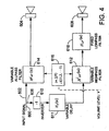
FIG. 4 , there is shown a block diagram of an exemplary embodiment ofarray processing module 504. An inputelectrical signal 600 is delivered to input 602 of variable allpass filter 614 and to input 606 ofinverter 610 that energizesvariable delay circuit 611.Inverter 610 provides a 180° relative phase shift at all frequencies with respect to the signal delivered oninput 602.Variable delay unit 611 has a response Hτ(Ω) = E-jΩτ which delays an electrical signal by a variable amount of time τ. This time delay controls the relative phase delay between the two drivers in an enclosure and the resulting directivity pattern. The output ofvariable delay circuit 611 energizes variablehigh pass filter 612. This filter functions to progressively exclude lower frequencies first to reduce low frequency cancellation. Reduction of cancellation occurs only above a set threshold volume, which is typically close to the maximum volume setting. Below this volume setting, cancellation is not affected. Above this threshold, the cut off frequency ofhigh pass filter 612 is progressively raised as volume level increases. - In one example, the variable
high pass filter 612 begins filtering above a volume level of V = 86 (in a system in which V = 100 represents maximum system volume, and radiated sound pressure level changes by approximately 0.5 dB per unit step in volume level). Afilter index sub-module 616 provides an index signal i as a function of the volume level V according to i = f 1(V) = u(V - 86) + u(V - 88) + u(V - 90) + u(V - 92) + u(V - 94) for V = 1,2,...,100, where u(V) is a unit step function. The index signal i increases with volume level V, incrementing every two volume levels between 86 and 94, as illustrated inFIG. 5 .
For volume levels below V = 86 the index signal is i = 0 and the cutoff frequency of the highpass filter is low enough so that the highpass filter has minimal if any effect on the signal (e.g., cutoff frequency at or below 210 Hz). The highpass filter frequency response is determined by the following equation:
where

array processing module 504 preserves directivity of the array for frequencies above 501 Hz at all volume levels. The directivity of the array for frequencies between 210 and 501 Hz is systematically altered at volume levels of 86 and above, that allows the loudspeaker system to play louder. - Since the phase response of the high-
pass filter 612 can potentially significantly modify the phase relationship between the two paths, thefirst path 602 includes avariable allpass filter 614 with a phase response that approximately matches that of the highpass filter, to at least partially compensate for any phase effects. A substantially exact match is possible
where the high-pass filter is critically damped, and the all-pass filter is a first order all-pass filter with the same cutoff frequency as the high pass filter. The variable all-pass filter 614 has a frequencyresponse 

filter index submodule 616 also supplies the index signal i to the variable all-pass filter 614 such that its phase approximately tracks the phase of the variable high-pass filter 612, which is accomplished by having the cutoff frequencies of the high pass and all pass filters track with changes in the index signal. The phases of

FIG. 6 .
The plots show that thephase 702 of the second order high-pass filter 612 is appropriately matched by thephase 704 of the first order all-pass filter 614. - In some implementations a fixed low-
pass filter 618 is included in thesecond path 606 to limit high-frequency output of onedriver 608, pointed to the inside in order to direct most of the high frequency acoustic energy from theoutside driver 604 pointed to the outside. The low-pass filter reduces output from the canceling driver at higher frequencies, so that high frequency information is only radiated by the outside drivers. In one implementation, the frequency response of the low-pass filter 618 is

- It may be advantageous to use smooth updating incident impulse response (IIR) digital filters for switching between successive indices. A blending sequence smoothly ramps successive filters in (and out) of the signal path while clearing the state of the filter during the transition free of artifacts.
- Referring to
FIG. 7 , a family of sixcurves 800 represent an example of changes in radiated acoustic power spectrum produced by thearray processing module 504 as compensated bydynamic equalizer module 502. The family ofcurves 800 are log plots of a radiated acoustic power spectrum S 2(ω) of a two-element speaker array relative to the radiated acoustic power spectrum S 1(ω) of a single speaker element (corresponding to the second speaker element being completely off):
flat curve 802 represents residual effects of a highly filtered ( f 5 = 501 Hz) second array element. The shape of successive curves changes nearly continuously from that ofcurve 804 representing the initial filtering ( f 0 = 210 Hz). For the initial filtering case,curve 804, the radiated power at low frequencies for the two-element array is much smaller than the radiated power of a single element (i.e., S2(ω) < S1(ω) ), due to destructive interference.Curve 804 at low frequencies shows that the quantity

- Referring to
FIG. 9 , a family of nine curves 810 represents an example of changes in a radiated acoustic power spectrum produced by another implementation of the array processing module. In this implementation, the array processing module simply attenuates the amplitude radiated by the inside driver (the canceling driver) of a two-driver array over successive volume levels to increase sound level. The amplitude radiated by the inside driver is attenuated from an initial value of -4 dB relative to the outside driver to a value of -40 dB (for maximum sound output), over nine volume levels from V = 86 to V = 94. A nearlyflat curve 812 represents residual effects of a highly attenuated (-40 dB) radiation from the inside driver. The shape of successive curves changes nearly continuously from that ofcurve 814 representing the initial attenuation (-4 dB). For the initial attenuation case,curve 814, the radiated power at low frequencies for the two-driver array is much smaller than the radiated power of a single driver (i.e., S2(ω) < S1(ω) ), due to destructive interference. -
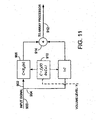
FIG. 11 shows a block diagram of an implementation of thedynamic equalizer module 502 whose parameters are chosen to compensate for change in the radiated acoustic power spectrum as the array directivity changes. The inputelectrical signal 900 comes from thesignal processing module 500, and the outputelectrical signal 912 goes to thearray processing module 504. The input electrical signal is split into a first signal onpath 902 and a second signal onpath 904. Afilter coefficient sub-module 910 provides a coefficient signal C as a function of volume level V according to
FIG. 12 . The coefficient signal C is applied tosubmodule 90 band submodule 908 to determine a proportion of a firstfiltered path 902, and a secondunfiltered path 904, that combine inadder 914 to produce the outputelectrical signal 912. The resultingoutput signal 912 is an equalized version of theinput signal 900 according to the transfer function: HEQ (ω) = 1 + C(HA (ω)-1), where HA (ω) is the frequency response of a filter that compensates for the effects of the second array driver. - For volume levels at or below V = 86, the coefficient signal C has the
value 1 and theoutput signal 912 is equalized according to a frequency response ofarray filter sub-module 906

poles 
zeros 

FIG. 7 . Table 2 corresponds to values used for the attenuated canceler implementation ofFIG. 8 . - For volume levels at or above V = 94 , the coefficient signal C has the
value 0 and theoutput signal 912 is the same as theinput signal 900, being equalized without the effects of the second array driver. For volume levels between 86 and 94, the output of the second array driver is gradually reduced starting from a volume setting of 84 while preserving the spectrum using thedynamic equalizer module 502, allowing the array to achieve significantly increased radiation at volume settings of 94 and above. Thedynamic equalizer module 502 filters the output signal appropriately to compensate for the changing effects of the second array driver (through filtering or attenuation).Table 1 Pole/Zero: ω0 (Hz) Q 
1600 0.73 
2750 0.92 
1680 0.74 
3990 0.95 Table 2 Pole/Zero: ω0 (Hz) Q 
727 1.16 
266 0.83 
684 1.14 
441 0.72 - The spectral responses |HEQ (ω))|2 for each of the six volume levels corresponding to the high-pass filtered canceler implementation of
FIG. 11 are shown inFIG. 9 . The flat curve 808 represents the equalization used for the relative spectrum corresponding tocurve 802, and thecurve 811 represents the equalization used for the relative spectrum corresponding tocurve 804. The match between the family ofcurves 800 representing the effects of the array processing and the family ofcurves 806 representing the equalization is preferably close enough to provide a substantially uniform radiated acoustic power spectrum. - The spectral responses |HEQ (ω)|2 for each of the nine volume levels of the attenuated canceler implementation of
FIG. 11 are shown inFIG. 10 . Theflat curve 818 represents the equalization used for the relative spectrum corresponding tocurve 812, and thecurve 820 represents the equalization used for the relative spectrum corresponding tocurve 814. The match between the family of curves 810 representing the effects of the array processing and the family ofcurves 816 representing the equalization is preferably close enough to provide a consistent acoustic power spectrum as perceived by a listener. - Referring to
FIG. 13 an alternate implementation of theloudspeaker driver module 306 includes asignal processing module 1000, adynamic equalizer module 1002, and anarray processing module 1004, with adetector 1006 used to provide a control signal for thedynamic equalizer module 1002 and thearray processing module 1004. In this implementation thevolume control 1008 determines the amplitude of electrical signals in thesignal processing module 1000, and thedetector 1006 determines level of one or more of the output electrical signals to provide an indication of the radiated power level. In this implementation, array directivity and compensating equalization are all changed as a function of the detected signal level. Control of directivity and acoustic volume characteristics as described above can be implemented using this detected control signal, the volume control, or any other parameter associated with operation of the array. - It is evident that those skilled in the art may now make numerous uses and modifications of and departures from the specific apparatus and techniques disclosed herein. For example, the array processing and the dynamic equalization can be performed within a single module. Each array of drivers in the loudspeaker system may have a separate loudspeaker driver module. Control of cancellation and acoustic volume characteristics and the associated compensating equalization can be performed for electrical signal components (e.g., based on a first audio channel) which are combined with other electrical signal components (e.g., based on a second audio channel) to drive drivers of an array. Consequently, the invention is to be construed as embracing each and every novel feature and novel combination of features present in or possessed by the apparatus and techniques herein disclosed and limited solely by the scope of the appended claims.
Claims (9)
- A method of electroacoustical transducing comprising
controlling audio electrical signals to be provided to a pair of electroacoustical transducers (302L, 302R) of an array, to achieve directivity and acoustic volume characteristics, as a function of a volume control (508) or detected signal level (1006), to reduce cancellation of the acoustic output signals from the electroacoustical transducers of the array, the controlling of the signals resulting in a change in the radiated acoustic power spectrum of the array as the characteristics are varied, and
adjusting equalization (502) to compensate for the change in the radiated acoustic power spectrum of the array. - The method of claim 1 in which the compensating for the change in the acoustic power spectrum comprises maintaining the radiated relative acoustic power spectrum substantially uniform.
- The method of claim 1 in which the controlling comprises reducing the amplitude of one of the audio electrical signals for higher acoustic volume levels.
- The method of claim 1 in which the controlling of the audio electrical signals comprises adjusting a level of one of the signals over a limited frequency range.
- The method of claim 1 in which controlling the audio electrical signals includes processing one of the signals in a high-pass filter (612) and processing the other of the signals in a complementary all-pass filter (614).
- Electroacoustical transducing apparatus comprising
an input terminal to receive an input audio electrical signal,
a plurality of electroacoustical transducers (302L, 302R) in an array, and
circuitry (504) constructed and arranged to generate two related output audio electrical signals (602, 606) from the input audio signal coupled to said electroacoustical transducers, and to achieve predefined directivity and acoustic volume characteristics as a function of a volume control (508) or detected signal level (1006), to reduce cancellation of the acoustic output signals from the electroacoustical transducers of the array, and equalization (502) that is adjusted to compensate for the change in the radiated acoustic power spectrum of the array. - The apparatus of claim 6 in which the equalization (502) comprises a dynamic equalizer.
- The apparatus of claim 7 in which the dynamic equalizer includes a pair of signal processing paths (902, 904) and a combiner (914) to combine signals that are processed on the two paths.
- An electroacoustical transducer array comprising,
a source of related electrical signal components
a plurality of electroacoustical transducers driven respectively by said related electrical signal components, and
electroacoustical transducing apparatus according to any of claims 6 to 8, wherein the source of related electrical signal components provides the input audio electrical signal.
Applications Claiming Priority (2)
| Application Number | Priority Date | Filing Date | Title |
|---|---|---|---|
| US665845 | 2003-09-18 | ||
| US10/665,845 US7519188B2 (en) | 2003-09-18 | 2003-09-18 | Electroacoustical transducing |
Publications (3)
| Publication Number | Publication Date |
|---|---|
| EP1517580A2 EP1517580A2 (en) | 2005-03-23 |
| EP1517580A3 EP1517580A3 (en) | 2006-06-07 |
| EP1517580B1 true EP1517580B1 (en) | 2009-11-11 |
Family
ID=34194768
Family Applications (1)
| Application Number | Title | Priority Date | Filing Date |
|---|---|---|---|
| EP04104232A Expired - Fee Related EP1517580B1 (en) | 2003-09-18 | 2004-09-02 | Electroacoustical transducing |
Country Status (6)
| Country | Link |
|---|---|
| US (1) | US7519188B2 (en) |
| EP (1) | EP1517580B1 (en) |
| JP (1) | JP4642418B2 (en) |
| CN (1) | CN1599510B (en) |
| DE (1) | DE602004024016D1 (en) |
| HK (1) | HK1074323A1 (en) |
Families Citing this family (88)
| Publication number | Priority date | Publication date | Assignee | Title |
|---|---|---|---|---|
| US7688992B2 (en) * | 2005-09-12 | 2010-03-30 | Richard Aylward | Seat electroacoustical transducing |
| DE602006018703D1 (en) * | 2006-04-05 | 2011-01-20 | Harman Becker Automotive Sys | Method for automatically equalizing a public address system |
| JP5003003B2 (en) * | 2006-04-10 | 2012-08-15 | パナソニック株式会社 | Speaker device |
| CN101558660B (en) * | 2006-05-22 | 2013-08-21 | 奥迪欧彼塞尔斯有限公司 | Apparatus and methods for generating pressure waves |
| US7995778B2 (en) * | 2006-08-04 | 2011-08-09 | Bose Corporation | Acoustic transducer array signal processing |
| US8483853B1 (en) | 2006-09-12 | 2013-07-09 | Sonos, Inc. | Controlling and manipulating groupings in a multi-zone media system |
| US8788080B1 (en) | 2006-09-12 | 2014-07-22 | Sonos, Inc. | Multi-channel pairing in a media system |
| US9202509B2 (en) | 2006-09-12 | 2015-12-01 | Sonos, Inc. | Controlling and grouping in a multi-zone media system |
| US7995771B1 (en) | 2006-09-25 | 2011-08-09 | Advanced Bionics, Llc | Beamforming microphone system |
| US7864968B2 (en) * | 2006-09-25 | 2011-01-04 | Advanced Bionics, Llc | Auditory front end customization |
| US8724827B2 (en) | 2007-05-04 | 2014-05-13 | Bose Corporation | System and method for directionally radiating sound |
| US9100748B2 (en) * | 2007-05-04 | 2015-08-04 | Bose Corporation | System and method for directionally radiating sound |
| US20080273722A1 (en) * | 2007-05-04 | 2008-11-06 | Aylward J Richard | Directionally radiating sound in a vehicle |
| US8483413B2 (en) * | 2007-05-04 | 2013-07-09 | Bose Corporation | System and method for directionally radiating sound |
| US8325936B2 (en) * | 2007-05-04 | 2012-12-04 | Bose Corporation | Directionally radiating sound in a vehicle |
| US20080273724A1 (en) * | 2007-05-04 | 2008-11-06 | Klaus Hartung | System and method for directionally radiating sound |
| US9560448B2 (en) * | 2007-05-04 | 2017-01-31 | Bose Corporation | System and method for directionally radiating sound |
| TWI369142B (en) * | 2008-01-22 | 2012-07-21 | Asustek Comp Inc | Audio system and a method for detecting and adjusting a sound field thereof |
| WO2009113002A1 (en) * | 2008-03-13 | 2009-09-17 | Koninklijke Philips Electronics N.V. | Speaker array and driver arrangement therefor |
| DE102008024380A1 (en) * | 2008-05-20 | 2009-11-26 | Repower Systems Ag | Signaling device for offshore wind farm |
| JP5565044B2 (en) * | 2010-03-31 | 2014-08-06 | ヤマハ株式会社 | Speaker device |
| US8923997B2 (en) | 2010-10-13 | 2014-12-30 | Sonos, Inc | Method and apparatus for adjusting a speaker system |
| JP5682244B2 (en) * | 2010-11-09 | 2015-03-11 | ソニー株式会社 | Speaker system |
| US11265652B2 (en) | 2011-01-25 | 2022-03-01 | Sonos, Inc. | Playback device pairing |
| US11429343B2 (en) | 2011-01-25 | 2022-08-30 | Sonos, Inc. | Stereo playback configuration and control |
| US8938312B2 (en) | 2011-04-18 | 2015-01-20 | Sonos, Inc. | Smart line-in processing |
| US9042556B2 (en) | 2011-07-19 | 2015-05-26 | Sonos, Inc | Shaping sound responsive to speaker orientation |
| US8811630B2 (en) | 2011-12-21 | 2014-08-19 | Sonos, Inc. | Systems, methods, and apparatus to filter audio |
| US9084058B2 (en) | 2011-12-29 | 2015-07-14 | Sonos, Inc. | Sound field calibration using listener localization |
| US9729115B2 (en) | 2012-04-27 | 2017-08-08 | Sonos, Inc. | Intelligently increasing the sound level of player |
| US9524098B2 (en) | 2012-05-08 | 2016-12-20 | Sonos, Inc. | Methods and systems for subwoofer calibration |
| USD721352S1 (en) | 2012-06-19 | 2015-01-20 | Sonos, Inc. | Playback device |
| US9690539B2 (en) | 2012-06-28 | 2017-06-27 | Sonos, Inc. | Speaker calibration user interface |
| US9668049B2 (en) | 2012-06-28 | 2017-05-30 | Sonos, Inc. | Playback device calibration user interfaces |
| US9106192B2 (en) | 2012-06-28 | 2015-08-11 | Sonos, Inc. | System and method for device playback calibration |
| US9219460B2 (en) | 2014-03-17 | 2015-12-22 | Sonos, Inc. | Audio settings based on environment |
| US9690271B2 (en) | 2012-06-28 | 2017-06-27 | Sonos, Inc. | Speaker calibration |
| US9706323B2 (en) | 2014-09-09 | 2017-07-11 | Sonos, Inc. | Playback device calibration |
| US8930005B2 (en) | 2012-08-07 | 2015-01-06 | Sonos, Inc. | Acoustic signatures in a playback system |
| US8965033B2 (en) | 2012-08-31 | 2015-02-24 | Sonos, Inc. | Acoustic optimization |
| US9008330B2 (en) | 2012-09-28 | 2015-04-14 | Sonos, Inc. | Crossover frequency adjustments for audio speakers |
| USD721061S1 (en) | 2013-02-25 | 2015-01-13 | Sonos, Inc. | Playback device |
| US9628895B2 (en) * | 2013-03-01 | 2017-04-18 | Lalkrushna Malaviya | Animal headphone apparatus |
| EP3063950B1 (en) * | 2013-10-30 | 2017-08-16 | L Acoustics | Sound system with improved adjustable directivity |
| US9226087B2 (en) | 2014-02-06 | 2015-12-29 | Sonos, Inc. | Audio output balancing during synchronized playback |
| US9226073B2 (en) | 2014-02-06 | 2015-12-29 | Sonos, Inc. | Audio output balancing during synchronized playback |
| US9264839B2 (en) | 2014-03-17 | 2016-02-16 | Sonos, Inc. | Playback device configuration based on proximity detection |
| US9367283B2 (en) | 2014-07-22 | 2016-06-14 | Sonos, Inc. | Audio settings |
| USD883956S1 (en) | 2014-08-13 | 2020-05-12 | Sonos, Inc. | Playback device |
| US9910634B2 (en) | 2014-09-09 | 2018-03-06 | Sonos, Inc. | Microphone calibration |
| US9952825B2 (en) | 2014-09-09 | 2018-04-24 | Sonos, Inc. | Audio processing algorithms |
| US10127006B2 (en) | 2014-09-09 | 2018-11-13 | Sonos, Inc. | Facilitating calibration of an audio playback device |
| US9891881B2 (en) | 2014-09-09 | 2018-02-13 | Sonos, Inc. | Audio processing algorithm database |
| US9973851B2 (en) | 2014-12-01 | 2018-05-15 | Sonos, Inc. | Multi-channel playback of audio content |
| WO2016172593A1 (en) | 2015-04-24 | 2016-10-27 | Sonos, Inc. | Playback device calibration user interfaces |
| US10664224B2 (en) | 2015-04-24 | 2020-05-26 | Sonos, Inc. | Speaker calibration user interface |
| USD886765S1 (en) | 2017-03-13 | 2020-06-09 | Sonos, Inc. | Media playback device |
| USD906278S1 (en) | 2015-04-25 | 2020-12-29 | Sonos, Inc. | Media player device |
| USD768602S1 (en) | 2015-04-25 | 2016-10-11 | Sonos, Inc. | Playback device |
| US20170085972A1 (en) | 2015-09-17 | 2017-03-23 | Sonos, Inc. | Media Player and Media Player Design |
| USD920278S1 (en) | 2017-03-13 | 2021-05-25 | Sonos, Inc. | Media playback device with lights |
| US10248376B2 (en) | 2015-06-11 | 2019-04-02 | Sonos, Inc. | Multiple groupings in a playback system |
| US9729118B2 (en) | 2015-07-24 | 2017-08-08 | Sonos, Inc. | Loudness matching |
| US9538305B2 (en) | 2015-07-28 | 2017-01-03 | Sonos, Inc. | Calibration error conditions |
| US9736610B2 (en) | 2015-08-21 | 2017-08-15 | Sonos, Inc. | Manipulation of playback device response using signal processing |
| US9712912B2 (en) | 2015-08-21 | 2017-07-18 | Sonos, Inc. | Manipulation of playback device response using an acoustic filter |
| US9693165B2 (en) | 2015-09-17 | 2017-06-27 | Sonos, Inc. | Validation of audio calibration using multi-dimensional motion check |
| EP3351015B1 (en) | 2015-09-17 | 2019-04-17 | Sonos, Inc. | Facilitating calibration of an audio playback device |
| US9743207B1 (en) | 2016-01-18 | 2017-08-22 | Sonos, Inc. | Calibration using multiple recording devices |
| US10003899B2 (en) | 2016-01-25 | 2018-06-19 | Sonos, Inc. | Calibration with particular locations |
| US11106423B2 (en) | 2016-01-25 | 2021-08-31 | Sonos, Inc. | Evaluating calibration of a playback device |
| US9886234B2 (en) | 2016-01-28 | 2018-02-06 | Sonos, Inc. | Systems and methods of distributing audio to one or more playback devices |
| US9864574B2 (en) | 2016-04-01 | 2018-01-09 | Sonos, Inc. | Playback device calibration based on representation spectral characteristics |
| US9860662B2 (en) | 2016-04-01 | 2018-01-02 | Sonos, Inc. | Updating playback device configuration information based on calibration data |
| US9763018B1 (en) | 2016-04-12 | 2017-09-12 | Sonos, Inc. | Calibration of audio playback devices |
| US9860670B1 (en) | 2016-07-15 | 2018-01-02 | Sonos, Inc. | Spectral correction using spatial calibration |
| US9794710B1 (en) | 2016-07-15 | 2017-10-17 | Sonos, Inc. | Spatial audio correction |
| US10372406B2 (en) | 2016-07-22 | 2019-08-06 | Sonos, Inc. | Calibration interface |
| US10459684B2 (en) | 2016-08-05 | 2019-10-29 | Sonos, Inc. | Calibration of a playback device based on an estimated frequency response |
| USD851057S1 (en) | 2016-09-30 | 2019-06-11 | Sonos, Inc. | Speaker grill with graduated hole sizing over a transition area for a media device |
| US10412473B2 (en) | 2016-09-30 | 2019-09-10 | Sonos, Inc. | Speaker grill with graduated hole sizing over a transition area for a media device |
| USD827671S1 (en) | 2016-09-30 | 2018-09-04 | Sonos, Inc. | Media playback device |
| US10712997B2 (en) | 2016-10-17 | 2020-07-14 | Sonos, Inc. | Room association based on name |
| JP6730384B2 (en) * | 2018-08-23 | 2020-07-29 | Ttr株式会社 | Electro-acoustic transducer |
| US11206484B2 (en) | 2018-08-28 | 2021-12-21 | Sonos, Inc. | Passive speaker authentication |
| US10299061B1 (en) | 2018-08-28 | 2019-05-21 | Sonos, Inc. | Playback device calibration |
| US11425521B2 (en) * | 2018-10-18 | 2022-08-23 | Dts, Inc. | Compensating for binaural loudspeaker directivity |
| US10734965B1 (en) | 2019-08-12 | 2020-08-04 | Sonos, Inc. | Audio calibration of a portable playback device |
Family Cites Families (13)
| Publication number | Priority date | Publication date | Assignee | Title |
|---|---|---|---|---|
| JPS57197996A (en) * | 1981-05-30 | 1982-12-04 | Sharp Corp | Speaker system for variable reproducing sound field characteristic |
| US4653606A (en) | 1985-03-22 | 1987-03-31 | American Telephone And Telegraph Company | Electroacoustic device with broad frequency range directional response |
| US4739514A (en) * | 1986-12-22 | 1988-04-19 | Bose Corporation | Automatic dynamic equalizing |
| GB2213677A (en) | 1987-12-09 | 1989-08-16 | Canon Kk | Sound output system |
| US5361381A (en) * | 1990-10-23 | 1994-11-01 | Bose Corporation | Dynamic equalizing of powered loudspeaker systems |
| JPH07162998A (en) * | 1993-12-03 | 1995-06-23 | Fujitsu Ten Ltd | On-vehicle acoustic device |
| GB9423346D0 (en) * | 1994-11-18 | 1995-01-11 | Amp Great Britain | Electrical interconnection system having retention and shorting features |
| US5870484A (en) | 1995-09-05 | 1999-02-09 | Greenberger; Hal | Loudspeaker array with signal dependent radiation pattern |
| US6175489B1 (en) * | 1998-06-04 | 2001-01-16 | Compaq Computer Corporation | Onboard speaker system for portable computers which maximizes broad spatial impression |
| US6118883A (en) * | 1998-09-24 | 2000-09-12 | Eastern Acoustic Works, Inc. | System for controlling low frequency acoustical directivity patterns and minimizing directivity discontinuities during frequency transitions |
| EP1157588A1 (en) | 1999-03-05 | 2001-11-28 | Etymotic Research, Inc | Directional microphone array system |
| DE60021011T2 (en) * | 1999-04-14 | 2005-12-01 | Matsushita Electric Industrial Co., Ltd., Kadoma | Drive circuit, electro-mechanical acoustic transducer, and portable terminal |
| US8139797B2 (en) * | 2002-12-03 | 2012-03-20 | Bose Corporation | Directional electroacoustical transducing |
-
2003
- 2003-09-18 US US10/665,845 patent/US7519188B2/en not_active Expired - Fee Related
-
2004
- 2004-09-02 DE DE602004024016T patent/DE602004024016D1/en active Active
- 2004-09-02 EP EP04104232A patent/EP1517580B1/en not_active Expired - Fee Related
- 2004-09-14 CN CN200410078641.5A patent/CN1599510B/en not_active Expired - Fee Related
- 2004-09-21 JP JP2004272920A patent/JP4642418B2/en not_active Expired - Fee Related
-
2005
- 2005-08-02 HK HK05106594.2A patent/HK1074323A1/en not_active IP Right Cessation
Also Published As
| Publication number | Publication date |
|---|---|
| CN1599510A (en) | 2005-03-23 |
| US7519188B2 (en) | 2009-04-14 |
| US20050063555A1 (en) | 2005-03-24 |
| JP4642418B2 (en) | 2011-03-02 |
| CN1599510B (en) | 2010-11-10 |
| HK1074323A1 (en) | 2005-11-04 |
| EP1517580A3 (en) | 2006-06-07 |
| DE602004024016D1 (en) | 2009-12-24 |
| EP1517580A2 (en) | 2005-03-23 |
| JP2005094777A (en) | 2005-04-07 |
Similar Documents
| Publication | Publication Date | Title |
|---|---|---|
| EP1517580B1 (en) | Electroacoustical transducing | |
| CN108781331B (en) | Audio enhancement for head mounted speakers | |
| US8175292B2 (en) | Audio signal processing | |
| US8050433B2 (en) | Apparatus and method to cancel crosstalk and stereo sound generation system using the same | |
| CN106507251B (en) | Stereo and FILTER TO CONTROL for multiple loudspeaker device | |
| US20090161880A1 (en) | Method and apparatus to create a sound field | |
| EP3439330B1 (en) | Adjusting the perceived elevation of an audio image on a solid cinema screen | |
| KR20050026928A (en) | Method of digital equalisation of a sound from loudspeakers in rooms and use of the method | |
| JP5788894B2 (en) | Method and audio system for processing a multi-channel audio signal for surround sound generation | |
| KR20050060789A (en) | Apparatus and method for controlling virtual sound | |
| JP2019083570A (en) | Method of crosstalk processing | |
| US7010128B1 (en) | Method of processing and reproducing an audio stereo signal and an audio stereo signal reproduction system | |
| US20120039480A1 (en) | Method and apparatus for improved directivity of an acoustic antenna | |
| KR101753065B1 (en) | Method and apparatus of adjusting distribution of spatial sound energy | |
| WO2020139838A1 (en) | Compact speaker system with controlled directivity | |
| CN110312198B (en) | Virtual sound source repositioning method and device for digital cinema | |
| WO2007035072A1 (en) | Apparatus and method to cancel crosstalk and stereo sound generation system using the same | |
| JP2001095085A (en) | Acoustic reproduction system, loudspeaker system and loudspeaker installation method |
Legal Events
| Date | Code | Title | Description |
|---|---|---|---|
| PUAI | Public reference made under article 153(3) epc to a published international application that has entered the european phase |
Free format text: ORIGINAL CODE: 0009012 |
|
| AK | Designated contracting states |
Kind code of ref document: A2 Designated state(s): AT BE BG CH CY CZ DE DK EE ES FI FR GB GR HU IE IT LI LU MC NL PL PT RO SE SI SK TR |
|
| AX | Request for extension of the european patent |
Extension state: AL HR LT LV MK |
|
| PUAL | Search report despatched |
Free format text: ORIGINAL CODE: 0009013 |
|
| AK | Designated contracting states |
Kind code of ref document: A3 Designated state(s): AT BE BG CH CY CZ DE DK EE ES FI FR GB GR HU IE IT LI LU MC NL PL PT RO SE SI SK TR |
|
| AX | Request for extension of the european patent |
Extension state: AL HR LT LV MK |
|
| 17P | Request for examination filed |
Effective date: 20061127 |
|
| 17Q | First examination report despatched |
Effective date: 20061221 |
|
| AKX | Designation fees paid |
Designated state(s): DE GB |
|
| GRAP | Despatch of communication of intention to grant a patent |
Free format text: ORIGINAL CODE: EPIDOSNIGR1 |
|
| GRAS | Grant fee paid |
Free format text: ORIGINAL CODE: EPIDOSNIGR3 |
|
| GRAA | (expected) grant |
Free format text: ORIGINAL CODE: 0009210 |
|
| AK | Designated contracting states |
Kind code of ref document: B1 Designated state(s): DE GB |
|
| REG | Reference to a national code |
Ref country code: GB Ref legal event code: FG4D |
|
| REF | Corresponds to: |
Ref document number: 602004024016 Country of ref document: DE Date of ref document: 20091224 Kind code of ref document: P |
|
| PLBE | No opposition filed within time limit |
Free format text: ORIGINAL CODE: 0009261 |
|
| STAA | Information on the status of an ep patent application or granted ep patent |
Free format text: STATUS: NO OPPOSITION FILED WITHIN TIME LIMIT |
|
| 26N | No opposition filed |
Effective date: 20100812 |
|
| PGFP | Annual fee paid to national office [announced via postgrant information from national office to epo] |
Ref country code: DE Payment date: 20180927 Year of fee payment: 15 |
|
| PGFP | Annual fee paid to national office [announced via postgrant information from national office to epo] |
Ref country code: GB Payment date: 20180927 Year of fee payment: 15 |
|
| REG | Reference to a national code |
Ref country code: DE Ref legal event code: R119 Ref document number: 602004024016 Country of ref document: DE |
|
| PG25 | Lapsed in a contracting state [announced via postgrant information from national office to epo] |
Ref country code: DE Free format text: LAPSE BECAUSE OF NON-PAYMENT OF DUE FEES Effective date: 20200401 |
|
| GBPC | Gb: european patent ceased through non-payment of renewal fee |
Effective date: 20190902 |
|
| PG25 | Lapsed in a contracting state [announced via postgrant information from national office to epo] |
Ref country code: GB Free format text: LAPSE BECAUSE OF NON-PAYMENT OF DUE FEES Effective date: 20190902 |