EP1517466B1 - A self-adaptive jitter buffer adjustment method for packet-switched network - Google Patents
A self-adaptive jitter buffer adjustment method for packet-switched network Download PDFInfo
- Publication number
- EP1517466B1 EP1517466B1 EP04019354A EP04019354A EP1517466B1 EP 1517466 B1 EP1517466 B1 EP 1517466B1 EP 04019354 A EP04019354 A EP 04019354A EP 04019354 A EP04019354 A EP 04019354A EP 1517466 B1 EP1517466 B1 EP 1517466B1
- Authority
- EP
- European Patent Office
- Prior art keywords
- jitter buffer
- packet
- jitter
- self
- adjustment
- Prior art date
- Legal status (The legal status is an assumption and is not a legal conclusion. Google has not performed a legal analysis and makes no representation as to the accuracy of the status listed.)
- Expired - Fee Related
Links
Images


Classifications
-
- H—ELECTRICITY
- H04—ELECTRIC COMMUNICATION TECHNIQUE
- H04L—TRANSMISSION OF DIGITAL INFORMATION, e.g. TELEGRAPHIC COMMUNICATION
- H04L47/00—Traffic control in data switching networks
- H04L47/10—Flow control; Congestion control
-
- H—ELECTRICITY
- H04—ELECTRIC COMMUNICATION TECHNIQUE
- H04J—MULTIPLEX COMMUNICATION
- H04J3/00—Time-division multiplex systems
- H04J3/02—Details
- H04J3/06—Synchronising arrangements
- H04J3/062—Synchronisation of signals having the same nominal but fluctuating bit rates, e.g. using buffers
- H04J3/0632—Synchronisation of packets and cells, e.g. transmission of voice via a packet network, circuit emulation service [CES]
-
- H—ELECTRICITY
- H04—ELECTRIC COMMUNICATION TECHNIQUE
- H04L—TRANSMISSION OF DIGITAL INFORMATION, e.g. TELEGRAPHIC COMMUNICATION
- H04L47/00—Traffic control in data switching networks
- H04L47/10—Flow control; Congestion control
- H04L47/22—Traffic shaping
-
- H—ELECTRICITY
- H04—ELECTRIC COMMUNICATION TECHNIQUE
- H04L—TRANSMISSION OF DIGITAL INFORMATION, e.g. TELEGRAPHIC COMMUNICATION
- H04L7/00—Arrangements for synchronising receiver with transmitter
- H04L7/0016—Arrangements for synchronising receiver with transmitter correction of synchronization errors
- H04L7/005—Correction by an elastic buffer
Definitions
- the present invention relates to a telecommunication method for packet-switched network, particularly to a self-adaptive jitter buffer adjustment method, which can be used in packet-switched network communication device.
- packet-switched network has been widely used for its advantages, such as low price, flexible protocol, good scalability and mature technology.
- Many real-time services such as IP telephony, TDM (Time Division Multiplexing) circuit emulation service and so on, have been or will be transfered over the packet-switched network.
- IP telephony IP telephony
- TDM Time Division Multiplexing
- the network delay of the data packet keeps changing randomly, which is called network jitter delay.
- the time when the periodicity data packets sent from the sender arrive at the receiver is unsure, and it poses an obstacle for the receiver to resume the periodicity data packets sent from the sender. Therefore, how to absorb the network jitters introduced by packet-switched network is the key point for transferring periodical real-time services, such as TDM, in packet-switched network.
- the common method for absorbing the network jitter is using a jitter buffer at the receiver.
- data packets 1, 2, 3, 4, 5 and 6 from the sender 100 reach the receiver 120 over packet-switched network 110. Due to the existence of the delay jitter, the sequence of these packets can be disturbed when they pass the packet-switched network 110, and will be changed when they reach the receiver 120.
- the sequence of these packets is: 1, 3, 2, 5, 4 and 6.
- the delay jitter brings about the network delay nd, and the receiver 120 uses jitter buffer 130 to absorb delay jitter, which causes the buffer delay bd.
- the gross output delay ted of data packets from the sender 100 to the jitter buffer is the sum of the network delay nd and the buffer delay bd.
- the size of the jitter buffer at least must be set to be 2 times packet rate ⁇ network jitter, and the normal working point of the jitter buffer at least must be set at packet rate ⁇ network jitter.
- the packet rate is 400pks/s (packets/second)
- a network jitter may be 20ms at one period of time, 300ms at the next period, and 10ms in another next period.
- the size of the jitter buffer will be set to absorb the 300ms jitter (as for packets rate at 400pks/s, the size of the jitter buffer is 240 packets) in both of the methods.
- the network jitter decreases to 20ms, the packets have to experience 120 extra packets queuing delays. Such a large delay is unsuitable for certain real-time applications. Therefore the jitter buffer must perform self-adaptive adjustment following the circumstances of the network. Under the above mentioned circumstances of the network, the packet delay is 120 packets when the circumstance is bad (300ms jitter), however, it can be decreased to 4 packets when the circumstance turns better (10ms) by using self-adaptive buffer.
- the traditional self-adaptive jitter buffer method adopts the prediction technique to the network jitter.
- the jitter prediction technique is based on either analyzing the jitters of the historically arrived packets, or directly on performing jitter prediction to changes of the filling level of the jitter buffer.
- a jitter buffer adjustment method based on historically arrived packet jitter was presented in the article " An Empirical Study of a Jitter Management Scheme for Video Teleconferencing", Donald L.Stone and Kevin Jeffay, Multimedia Systems Volume 2, Number 2, 1995 ; a self-adaptive jitter buffer adjustment method based on the changes of the filling level of the jitter buffer was presented in the article " An adaptive stream synchronization protocol”, written by Kurt Rothermel and Tobias Helbig and published in "Network and Operating System Support for Digital Audio and Video", April 1995 pages 189-202 , in which the architecture of self-adaptive adjustment theory is shown in Fig.2.
- HWM High Water Mark
- LWM Low Water Mark
- UTB User Target Boundary
- LTB Lower Target Boundary
- the self-adaptive adjustment method above was developed according to the characteristics of real-time services, and especially optimized for transferring real-time voice over the packet-switched network. More specifically, these methods should take into account the compromise between the end-to-end delay and the packet-dropping rate (as for real-time voice service, the typical value of the dropping rate is 5%).
- the longer the buffer length is set to be the larger the jitter can be absorbed, and the smaller the packets dropping rate is, but the longer the end-to-end delay is; on the contrary, the shorter the buffer length is set to be, the smaller the jitter can be absorbed, and the larger packets dropping rate is, but the shorter the end-to-end delay is.
- TDM service entails small packet-dropping rates, for example, the frame dropping rate of 2.048Mbits/s E1 circuit simulation service on the Ethernet is defined to be lower than 7x10 -6 by MEF (Metro Ethernet Forum).
- MEF Micro Ethernet Forum
- Document WO0042749A discloses a self-adaptive jitter buffer adjustment method for packet-switched networks according to the preamble of claim 1.
- Document US 5,623,483 discloses a jitter buffer for packet-switched networks having a fixed size. Before a data transmission of the data packets across the packet-switched network, the probable delays of the data packets is estimated and the buffer size calculated accordingly. If during data transmission across the packet-switched network the buffer size proves to be too small, all data packets in the buffer are simply shifted towards the output end, the packets closest to the output are discarded.
- the object of the present invention is to provide a self-adaptive jitter buffer adjustment method for packet-switched network, which is capable of tracking the network jitter effectively, adjusting the parameters of the jitter buffer dynamically, ensuring the end-to-end performance, and outputing the ordered packets.
- the Real-time Transport Protocol/Real-time Transport Control Protocol (RTP/RTCP) Data is adopted for transmission of the data packets described above.
- the parameters of the jitter buffer are adjusted according to both the indication of the packet delay and the changes of the filling level of the buffer. Packet dropping rate is not taken into account during the self-adaptive adjustment procedure.
- the present method satisfies the demand of transferring TDM service over packet-switched network, and realizes the object of tracking network jitter dynamically.
- the presented method greatly lowers the complicacy and computational costs of self-adaptive jitter buffer adjustment algorithm.
- the impact of self-adaptive jitter buffer adjustment on the performance of the whole system is greatly reduced.
- This invention also effectively deals with the delay spikes, which is hard for ordinary self-adaptive jitter buffer to process, realizes rebuilding of the packet sequence for output, and ensures normal communication from one end to the other.
- Fig. 3 is a flow chart showing the method of adjusting the self-adaptive jitter buffer according to this invention, which comprises the following steps of:
- a command for negative adjustment will be called by the system, and the jitter buffer will enter the negative adjustment procedure, Max m ⁇ Max ⁇ m - 1 - ⁇ Min m ⁇ Min ⁇ m - 1 - ⁇ where ⁇ is the preset value for performing negative adjustment.
- the normal working point of the current jitter buffer is lowered to the minimum threshold C by dropping some data packets of the jitter buffer during negative adjustment to ⁇ the jitter buffer. Then, the above steps are repeated in the next negative adjustment period m+1.
- Either the number of the data packets or the bits of the data packets can be used to denote the said filling level of the jitter buffer.
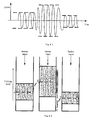
- Fig. 4.1 is a block diagram of a typical network jitter.
- the network presents different jitter features at different time periods.
- Fig. 4.2 is a block diagram showing the self-adaptive jitter buffer adjustment based on the network jitter according to this invention.
- the normal working point adjusts itself to point A to absorb the current network jitter adequately.
- the network jitter will increase gradually due to the changes of the condition of the network (such as the congestion).
- the indication of packet delay appears, and the jitter buffer will enter the positive adjustment procedure.
- the normal working point of the jitter buffer will ascend from point A to point B to absorb the current network jitter.
- the network jitter will decrease gradually due to the changes of the condition of the network (such as the disappearance of the congestion, the upgrading of the condition of the network), the filling level of the jitter buffer will descend, and the jitter buffer will enter the negative adjustment procedure.
- the normal working point of the jitter buffer will descend from point B to the minimum threshold C.
- the normal working point of the jitter buffer will ascend from the minimum threshold C to point D to absorb the current network jitter.
Description
- The present invention relates to a telecommunication method for packet-switched network, particularly to a self-adaptive jitter buffer adjustment method, which can be used in packet-switched network communication device.
- At present, packet-switched network has been widely used for its advantages, such as low price, flexible protocol, good scalability and mature technology. Many real-time services, such as IP telephony, TDM (Time Division Multiplexing) circuit emulation service and so on, have been or will be transfered over the packet-switched network. When real-time periodical service is being transferred over packet-switched network, due to queuing, congestion and variety in signal path, the network delay of the data packet keeps changing randomly, which is called network jitter delay. Thus, the time when the periodicity data packets sent from the sender arrive at the receiver is unsure, and it poses an obstacle for the receiver to resume the periodicity data packets sent from the sender. Therefore, how to absorb the network jitters introduced by packet-switched network is the key point for transferring periodical real-time services, such as TDM, in packet-switched network.
- Currently, the common method for absorbing the network jitter is using a jitter buffer at the receiver. As shown in Fig.1,
data packets sender 100 reach thereceiver 120 over packet-switchednetwork 110. Due to the existence of the delay jitter, the sequence of these packets can be disturbed when they pass the packet-switchednetwork 110, and will be changed when they reach thereceiver 120. The sequence of these packets is: 1, 3, 2, 5, 4 and 6. At the same time, the delay jitter brings about the network delay nd, and thereceiver 120 usesjitter buffer 130 to absorb delay jitter, which causes the buffer delay bd. Thus, the gross output delay ted of data packets from thesender 100 to the jitter buffer is the sum of the network delay nd and the buffer delay bd. - In order to eliminate the delay jitter introduced by packet network, the size of the jitter buffer at least must be set to be 2 times packet rate × network jitter, and the normal working point of the jitter buffer at least must be set at packet rate × network jitter. For example, assuming the packet rate is 400pks/s (packets/second), each packet has to experience 400×0.01=4 extra packets of queuing delays for absorbing 10ms of network jitter. At present, there are mainly three types of methods for absorbing network jitters by using jitter buffers at the receiver. 1) A jitter buffer of fixed size. Such as the earlier experimental system for transferring TDM service on the Ethernet, in which the network jitter is assumed to be small, hence the fixed size jitter buffer is to be used. 2) A jitter buffer of successively increasing size. As an improvement to the first method, it uses the successively increasing size jitter buffer to absorb the largest network jitter. 3) Self-adaptive jitter buffer, which is a kind of jitter buffer whose size can be adjusted dynamically. This method has drawn growing attention in transferring TDM service over packet-switched network. This is mainly because of the wide range of services it undertakes, the complexity of the network, and the varied jitters under different circumstances of the network, in the practical packet-switched network. For example, a network jitter may be 20ms at one period of time, 300ms at the next period, and 10ms in another next period. Obviously, neither the jitter buffer of fixed size nor the jitter buffer of successively increasing size fits the circumstances of the network, because the size of the jitter buffer will be set to absorb the 300ms jitter (as for packets rate at 400pks/s, the size of the jitter buffer is 240 packets) in both of the methods. Even if the network jitter decreases to 20ms, the packets have to experience 120 extra packets queuing delays. Such a large delay is unsuitable for certain real-time applications. Therefore the jitter buffer must perform self-adaptive adjustment following the circumstances of the network. Under the above mentioned circumstances of the network, the packet delay is 120 packets when the circumstance is bad (300ms jitter), however, it can be decreased to 4 packets when the circumstance turns better (10ms) by using self-adaptive buffer.
- Generally, the traditional self-adaptive jitter buffer method adopts the prediction technique to the network jitter. The jitter prediction technique is based on either analyzing the jitters of the historically arrived packets, or directly on performing jitter prediction to changes of the filling level of the jitter buffer. For example, a jitter buffer adjustment method based on historically arrived packet jitter was presented in the article "An Empirical Study of a Jitter Management Scheme for Video Teleconferencing", Donald L.Stone and Kevin Jeffay, Multimedia Systems ; a self-adaptive jitter buffer adjustment method based on the changes of the filling level of the jitter buffer was presented in the article "An adaptive stream synchronization protocol", written by Kurt Rothermel and Tobias Helbig and published in "Network and Operating System Support for Digital Audio and Video", April 1995 pages 189-202, in which the architecture of self-adaptive adjustment theory is shown in Fig.2. A large amount of threshold values and counters have been used in this self-adaptive adjustment procedure, HWM (High Water Mark) and LWM (Low Water Mark) are respectively defined as the high and low overflow threshold of the jitter buffer. Between HWM and LWM, and within the area of UTB (Upper Target Boundary) and LTB (Lower Target Boundary) is a target working zone. When the filling level is out of the working zone, the working parameters of the buffer will be adjusted by the self-adaptive procedure, and the filling level will be dragged back to the working zone, where HWM, LWM, UTB, LTB should all be adjusted according to the condition of network jitter. The self-adaptive adjustment method above was developed according to the characteristics of real-time services, and especially optimized for transferring real-time voice over the packet-switched network. More specifically, these methods should take into account the compromise between the end-to-end delay and the packet-dropping rate (as for real-time voice service, the typical value of the dropping rate is 5%). Generally speaking, the longer the buffer length is set to be, the larger the jitter can be absorbed, and the smaller the packets dropping rate is, but the longer the end-to-end delay is; on the contrary, the shorter the buffer length is set to be, the smaller the jitter can be absorbed, and the larger packets dropping rate is, but the shorter the end-to-end delay is. In practice, TDM service entails small packet-dropping rates, for example, the frame dropping rate of 2.048Mbits/s E1 circuit simulation service on the Ethernet is defined to be lower than 7x10⁻⁶ by MEF (Metro Ethernet Forum). Obviously, if we take into account the packet dropping rate when adjusting the jitter buffer, quite a lot of statistic information is needed, and this will increase the complicacy and computational costs of self-adaptive adjustment algorithm.
- Document
WO0042749A claim 1. - Document
US 5,623,483 discloses a jitter buffer for packet-switched networks having a fixed size. Before a data transmission of the data packets across the packet-switched network, the probable delays of the data packets is estimated and the buffer size calculated accordingly. If during data transmission across the packet-switched network the buffer size proves to be too small, all data packets in the buffer are simply shifted towards the output end, the packets closest to the output are discarded. - The object of the present invention is to provide a self-adaptive jitter buffer adjustment method for packet-switched network, which is capable of tracking the network jitter effectively, adjusting the parameters of the jitter buffer dynamically, ensuring the end-to-end performance, and outputing the ordered packets.
- This object is attained through the following technical solution, that is a self-adaptive jitter buffer adjustment method for packet-switched network, comprising the steps of:
- a) initializing a jitter buffer, receiving data packets and storing the packets into the jitter buffer;
- b) dynamically detecting sequence numbers of the data packets in the jitter buffer and performing a positive adjustment to the jitter buffer, according to an indication of a sequence number of packet delaying, to absorb larger network jitter;
- c) periodically detecting a filling level of the jitter buffer and performing a negative adjustment to the jitter buffer, when the filling level descends, to match smaller network jitter.
- The Real-time Transport Protocol/Real-time Transport Control Protocol (RTP/RTCP) Data is adopted for transmission of the data packets described above.
- In the present method, the parameters of the jitter buffer are adjusted according to both the indication of the packet delay and the changes of the filling level of the buffer. Packet dropping rate is not taken into account during the self-adaptive adjustment procedure. Thus, the present method satisfies the demand of transferring TDM service over packet-switched network, and realizes the object of tracking network jitter dynamically. Compared with traditional methods for self-adaptive buffer adjustment, the presented method greatly lowers the complicacy and computational costs of self-adaptive jitter buffer adjustment algorithm. At the same time, the impact of self-adaptive jitter buffer adjustment on the performance of the whole system is greatly reduced.
- This invention also effectively deals with the delay spikes, which is hard for ordinary self-adaptive jitter buffer to process, realizes rebuilding of the packet sequence for output, and ensures normal communication from one end to the other.
-
- Fig. 1
- is a block diagram of jitter delay and the absorbing of jitter delay, disturbed sequence of arrived packets and re-arranged sequence of the packets.
- Fig. 2
- is a block diagram of the architecture of self-adaptive jitter buffer according to traditional method.
- Fig. 3
- is a flow chart showing steps of adjusting the self-adaptive jitter buffer according to this invention.
- Fig. 4.1
- is a block diagram of a typical network jitter.
- Fig. 4.2
- is a block diagram showing the self-adaptive jitter buffer adjustment based on the network jitter in this invention.
- The invention will be explained in more details with reference to the accompanying drawings as following.
- Fig. 3 is a flow chart showing the method of adjusting the self-adaptive jitter buffer according to this invention, which comprises the following steps of:
- 1) initializing a jitter buffer:
Parameters, such as the negative adjustment period T of jitter buffer, the time interval ΔS for sampling the filling level of the jitter buffer during negative adjustment period T, the minimum threshold C of the normal working point of the jitter buffer, the initial maximum value (Max(0)) and the initial minimum value (Min(0)) of the filling level of jitter buffer, the initial normal working point A(0) of the jitter buffer, the initial data packet number N(0), and the difference value σ satisfying the condition of the negative adjustment, of the self-adaptive jitter buffer for dynamic adjustment will be preset in this initializing step.
Upon completion of jitter buffer initialization, receiving of data packets begins. The Real-time Transport Protocol/Real-time Transport Control Protocol (RTP/RTCP) can be adopted for transmission of data packets between sender and receiver. - 2) detecting the indication of the packet delay and performing positive adjustment:
Generally, the sender periodically sends data packets of sequence numbers to the packet-switched network, and the data packets may be non-sequentially reached the receiver in a non-periodical way.
During a local clock period, the receiver fetches a data packet from the jitter buffer. Assuming the searched sequence number of packet is N(n), the system will search if there is a data packet with the number that matches this sequence number in the jitter buffer based on the sequence number of packet N(n). If there is, this packet with sequence number N(n) will be taken out and output. The current packet sequence number will be updated to N(n+1), and the system will keep searching for the matched sequence number to ensure that the packet output will be in order. If there is no sequence number of packet that matches the current sequence number N(n), the packet with sequence number N(n) will arrive after some delay and the jitter buffer will enter its positive adjustment procedure.
In the positive adjustment procedure, some data packets will be inserted into the jitter buffer to absorb larger network. jitter, and those data packets in the jitter buffer, whose sequence number is smaller than the current sequence number N(n), will be discarded (these packets are the overdue packets needing processing no longer.). After that, the current sequence number will be updated to N(n+1). In the next local clock period, the above steps are repeated.
Said inserted packets can be the data packets which have been output from the jitter buffer at previous times. - 3) detecting the filling level of the jitter buffer and performing the negative adjustment:
Various methods can be adopted to detect the filling level of the jitter buffer. As a preferred embodiment, here, the filling level is sampled several times in one period to ascertain the maximum value and the minimum value of the filling level of the jitter buffer, and the maximum value and the minimum value can basically reflect the condition of the filling level of the jitter buffer. - In order to reflect the changes of the filling level of the jitter buffer, here, compare the maximum value Max(m) and the minimum value Min(m) of the filling level of the jitter buffer in the mth negative adjustment period T(m) with the maximum value (Max(m-1)) and the minimum value (Min(m-1)) of the filling level of the jitter buffer in the previous negative adjustment period T(m-1). If the following conditions are satisfied, it means the filling level of the jitter buffer descends in this period. A command for negative adjustment will be called by the system, and the jitter buffer will enter the negative adjustment procedure,


where σ is the preset value for performing negative adjustment. - The normal working point of the current jitter buffer is lowered to the minimum threshold C by dropping some data packets of the jitter buffer during negative adjustment to σthe jitter buffer. Then, the above steps are repeated in the next negative adjustment period m+1.
- Either the number of the data packets or the bits of the data packets can be used to denote the said filling level of the jitter buffer.
- Fig. 4.1 is a block diagram of a typical network jitter. The network presents different jitter features at different time periods. Fig. 4.2 is a block diagram showing the self-adaptive jitter buffer adjustment based on the network jitter according to this invention. When the system startups, the normal working point adjusts itself to point A to absorb the current network jitter adequately. After a while, the network jitter will increase gradually due to the changes of the condition of the network (such as the congestion). The indication of packet delay appears, and the jitter buffer will enter the positive adjustment procedure. The normal working point of the jitter buffer will ascend from point A to point B to absorb the current network jitter. Then, the network jitter will decrease gradually due to the changes of the condition of the network (such as the disappearance of the congestion, the upgrading of the condition of the network), the filling level of the jitter buffer will descend, and the jitter buffer will enter the negative adjustment procedure. The normal working point of the jitter buffer will descend from point B to the minimum threshold C. After that, because the size of the jitter buffer is not big enough to absorb the network jitter, indication of packet delay appears again, and the jitter buffer will enter the positive adjustment procedure. The normal working point of the jitter buffer will ascend from the minimum threshold C to point D to absorb the current network jitter.
- The invention has been described in more details with reference to the accompanying drawings in above. The person who skills in the art can make various modifications based on the above description of the invention, such as means of detecting the indication of the packets delay, means of detecting the filling level of the jitter buffer, the adjustment object of the buffer and so on. Therefore, some detail in the embodiment cannot be the definition of the invention. The invention will make the scope defined by claims attached as the protection of the invention.
Claims (6)
- A self-adaptive jitter buffer adjustment method for a packet-switched network (110), wherein the said method comprises the steps of:a) initializing a jitter buffer (130), receiving data packets (1, 2, ..., 6) and storing these packets (1, 2, ..., 6) into the jitter buffer (130);b) dynamically detecting sequence numbers of the packets (1, 2, ..., 6) in said jitter buffer (130) and performing a positive adjustment to said jitter buffer (130), according to an indication of a sequence number of the packet (2, 4) delaying, to absorb larger network jitters;
characterized by the step ofc) periodically detecting a filling level of said jitter buffer (130) and performing a negative adjustment to said jitter buffer (130), when the filling level descends, to match smaller network jitters. - A self-adaptive jitter buffer adjustment method for packet-switched network according to claim 1, wherein in step a) the Real-time Transport Protocol/Real-time Transport Control Protocol (RTP/RTCP) is adopted for transmission of the data packets.
- A self-adaptive jitter buffer adjustment method for packet-switched network according to claim 1 or claim 2, wherein step b) further comprises the steps of:b1) searching whether there is a data packet having a current sequence number of packet (N(n)) in the jitter buffer (130) within a local clock period, and if there is, outputting the data packet and updating the current sequence number (N(n)) to the next (N(n+1));b2) if there is no data packet having the current packet sequence number, inserting some data packets into the jitter buffer (130), discarding those data packets whose number is smaller than the current sequence number (N(n)), and updating the current sequence number (N(n)) to the next (N(n+1));b3) repeating step b1) and step b2) within the next clock period.
- A self-adaptive jitter buffer adjustment method for packet-switched network according to claim 3, wherein in step b2), the inserted packets may be data packets which have been output from the jitter buffer (130) at a previous time.
- A self-adaptive jitter buffer adjustment method for packet-switched network according to claim 1 or claim 2, wherein said step c) further comprises the steps of:c1) sampling the filling level of the jitter buffer (130) for several times in the m-th negative adjustment period (T(m)) of the jitter buffer (130), obtaining the maximum value (Max(m)) and the minimum value (Min(m)) of the filling level of the jitter buffer (130) in the negative adjustment period;c2) comparing said maximum value (Max(m)) and said minimum value (Min(m)) with the maximum value (Max(m-1)) and the minimum value (Min(m-1)) of the filling level of the jitter buffer in the previous negative adjustment period (T(m-1)), obtaining the changes of the filling level;c3) if the filling level descends and satisfies the following conditions:

and
performing negative adjustment to the jitter buffer (130) to match smaller network jitter, where σ is the preset value for performing negative adjustment.c4) repeating step c1) to step c3) in the next negative adjustment period (T(m+1)) of the jitter buffer (130). - A self-adaptive jitter buffer adjustment method for packet-switched network according to claim 5, wherein in said step c), a current normal working point of the current jitter buffer (130) is lowered to the minimum threshold (C) by discarding some data packets in the jitter buffer (130) during the negative adjustment to jitter buffer (130).
Applications Claiming Priority (2)
| Application Number | Priority Date | Filing Date | Title |
|---|---|---|---|
| CNB031510167A CN1320805C (en) | 2003-09-17 | 2003-09-17 | Regulating method of adaptive scillation buffer zone of packet switching network |
| CN03151016 | 2003-09-17 |
Publications (3)
| Publication Number | Publication Date |
|---|---|
| EP1517466A2 EP1517466A2 (en) | 2005-03-23 |
| EP1517466A3 EP1517466A3 (en) | 2005-06-01 |
| EP1517466B1 true EP1517466B1 (en) | 2007-11-07 |
Family
ID=34156537
Family Applications (1)
| Application Number | Title | Priority Date | Filing Date |
|---|---|---|---|
| EP04019354A Expired - Fee Related EP1517466B1 (en) | 2003-09-17 | 2004-08-14 | A self-adaptive jitter buffer adjustment method for packet-switched network |
Country Status (4)
| Country | Link |
|---|---|
| US (1) | US8218579B2 (en) |
| EP (1) | EP1517466B1 (en) |
| CN (1) | CN1320805C (en) |
| DE (1) | DE602004009874D1 (en) |
Families Citing this family (33)
| Publication number | Priority date | Publication date | Assignee | Title |
|---|---|---|---|---|
| US7573894B2 (en) * | 2004-02-17 | 2009-08-11 | Mitel Networks Corporation | Method of dynamic adaptation for jitter buffering in packet networks |
| US7674096B2 (en) * | 2004-09-22 | 2010-03-09 | Sundheim Gregroy S | Portable, rotary vane vacuum pump with removable oil reservoir cartridge |
| US7599399B1 (en) * | 2005-04-27 | 2009-10-06 | Sprint Communications Company L.P. | Jitter buffer management |
| CN101273649A (en) * | 2005-07-25 | 2008-09-24 | 艾利森电话股份有限公司 | Apparatus and method for improving switching characteristic of wireless access network |
| US7701980B1 (en) * | 2005-07-25 | 2010-04-20 | Sprint Communications Company L.P. | Predetermined jitter buffer settings |
| US8213444B1 (en) | 2006-02-28 | 2012-07-03 | Sprint Communications Company L.P. | Adaptively adjusting jitter buffer characteristics |
| US8000238B2 (en) * | 2006-08-04 | 2011-08-16 | Cisco Technology, Inc. | System and method for detecting and regulating congestion in a communications environment |
| US7944823B1 (en) * | 2006-09-01 | 2011-05-17 | Cisco Technology, Inc. | System and method for addressing dynamic congestion abatement for GSM suppression/compression |
| EP1931068A1 (en) * | 2006-12-04 | 2008-06-11 | Nokia Siemens Networks Gmbh & Co. Kg | Method of adaptively dejittering packetized signals buffered at the receiver of a communication network node |
| US20080168510A1 (en) * | 2007-01-10 | 2008-07-10 | At&T Knowledge Ventures, Lp | System and method of routing video data |
| US9019830B2 (en) * | 2007-05-15 | 2015-04-28 | Imagine Communications Corp. | Content-based routing of information content |
| FI120284B (en) | 2007-07-20 | 2009-08-31 | Tellabs Oy | Control of the fill rate in a jitter buffer |
| JP5153891B2 (en) * | 2008-01-25 | 2013-02-27 | テレフオンアクチーボラゲット エル エム エリクソン(パブル) | A simple adaptive jitter buffering algorithm for network nodes |
| FR2933562B1 (en) * | 2008-07-03 | 2012-12-14 | Enensys Technologies | FLOW GENERATING DEVICE, METHOD OF CALCULATING A FILLING LEVEL OF AN INPUT BUFFER WITHIN THE DEVICE, AND FLOW CONTROL METHOD |
| JP5369814B2 (en) * | 2009-03-26 | 2013-12-18 | ソニー株式会社 | Receiving device and time correction method for receiving device |
| TWI521985B (en) | 2010-07-08 | 2016-02-11 | 瑞昱半導體股份有限公司 | Wireless communication system and method for adjusting used depth of buffer unit in wireless communication system |
| CN101969403B (en) * | 2010-10-25 | 2013-01-02 | 武汉烽火网络有限责任公司 | E-Model-based dejittering buffer management method |
| CN102098091B (en) * | 2011-01-10 | 2013-07-31 | 东南大学 | Self-adaptive switching method of multi-cell cooperative downward transmission modes |
| JP6031752B2 (en) * | 2011-12-05 | 2016-11-24 | 沖電気工業株式会社 | Voice communication apparatus and program |
| US9787416B2 (en) | 2012-09-07 | 2017-10-10 | Apple Inc. | Adaptive jitter buffer management for networks with varying conditions |
| JP6163741B2 (en) * | 2012-11-30 | 2017-07-19 | ヤマハ株式会社 | Method and apparatus for determining buffer size of network reception buffer and network session system |
| CN103888381A (en) | 2012-12-20 | 2014-06-25 | 杜比实验室特许公司 | Device and method used for controlling jitter buffer |
| JP6501589B2 (en) * | 2015-03-31 | 2019-04-17 | キヤノン株式会社 | Communication device, control method of communication device, and program |
| US9866596B2 (en) | 2015-05-04 | 2018-01-09 | Qualcomm Incorporated | Methods and systems for virtual conference system using personal communication devices |
| US9906572B2 (en) | 2015-08-06 | 2018-02-27 | Qualcomm Incorporated | Methods and systems for virtual conference system using personal communication devices |
| US10015216B2 (en) | 2015-08-06 | 2018-07-03 | Qualcomm Incorporated | Methods and systems for virtual conference system using personal communication devices |
| US9634947B2 (en) | 2015-08-28 | 2017-04-25 | At&T Mobility Ii, Llc | Dynamic jitter buffer size adjustment |
| CN106559159B (en) * | 2015-09-30 | 2018-11-16 | 北京华为数字技术有限公司 | Circuit emulation service clock synchronization detecting method and device |
| WO2017095276A1 (en) * | 2015-11-30 | 2017-06-08 | Telefonaktiebolaget Lm Ericsson (Publ) | Method and receiving device for adapting a play-out rate of a jitter buffer |
| CN107770124A (en) * | 2016-08-15 | 2018-03-06 | 北京信威通信技术股份有限公司 | A kind of dynamic control method and device of ip voice buffering area |
| US10313416B2 (en) * | 2017-07-21 | 2019-06-04 | Nxp B.V. | Dynamic latency control |
| GB201720612D0 (en) | 2017-12-11 | 2018-01-24 | Nordic Semiconductor Asa | Radio communications |
| CN111105778A (en) * | 2018-10-29 | 2020-05-05 | 阿里巴巴集团控股有限公司 | Speech synthesis method, speech synthesis device, computing equipment and storage medium |
Family Cites Families (26)
| Publication number | Priority date | Publication date | Assignee | Title |
|---|---|---|---|---|
| US5623483A (en) * | 1995-05-11 | 1997-04-22 | Lucent Technologies Inc. | Synchronization system for networked multimedia streams |
| US5808767A (en) * | 1996-05-30 | 1998-09-15 | Bell Atlantic Network Services, Inc | Fiber optic network with wavelength-division-multiplexed transmission to customer premises |
| US6434606B1 (en) * | 1997-10-01 | 2002-08-13 | 3Com Corporation | System for real time communication buffer management |
| US6452950B1 (en) * | 1999-01-14 | 2002-09-17 | Telefonaktiebolaget Lm Ericsson (Publ) | Adaptive jitter buffering |
| US6512761B1 (en) * | 1999-02-02 | 2003-01-28 | 3Com Corporation | System for adjusting billing for real-time media transmissions based on delay |
| GB2351884B (en) | 1999-04-10 | 2002-07-31 | Peter Strong | Data transmission method |
| US6658027B1 (en) * | 1999-08-16 | 2003-12-02 | Nortel Networks Limited | Jitter buffer management |
| US6747999B1 (en) * | 1999-11-15 | 2004-06-08 | Siemens Information And Communication Networks, Inc. | Jitter buffer adjustment algorithm |
| US6683889B1 (en) * | 1999-11-15 | 2004-01-27 | Siemens Information & Communication Networks, Inc. | Apparatus and method for adaptive jitter buffers |
| US6693921B1 (en) * | 1999-11-30 | 2004-02-17 | Mindspeed Technologies, Inc. | System for use of packet statistics in de-jitter delay adaption in a packet network |
| US6862298B1 (en) * | 2000-07-28 | 2005-03-01 | Crystalvoice Communications, Inc. | Adaptive jitter buffer for internet telephony |
| CN1119890C (en) * | 2000-09-30 | 2003-08-27 | 华为技术有限公司 | Anti-loss treating method for IP speech sound data package |
| SE0004839D0 (en) * | 2000-12-22 | 2000-12-22 | Ericsson Telefon Ab L M | Method and communication apparatus in a communication system |
| US20020172229A1 (en) * | 2001-03-16 | 2002-11-21 | Kenetec, Inc. | Method and apparatus for transporting a synchronous or plesiochronous signal over a packet network |
| ATE353503T1 (en) * | 2001-04-24 | 2007-02-15 | Nokia Corp | METHOD FOR CHANGING THE SIZE OF A CLIMBER BUFFER FOR TIME ALIGNMENT, COMMUNICATIONS SYSTEM, RECEIVER SIDE AND TRANSCODER |
| US20030021287A1 (en) * | 2001-05-04 | 2003-01-30 | Appian Communications, Inc. | Communicating data between TDM and packet based networks |
| US6757292B2 (en) * | 2001-07-11 | 2004-06-29 | Overture Networks, Inc. | Automatic adjustment of buffer depth for the correction of packet delay variation |
| US7006511B2 (en) * | 2001-07-17 | 2006-02-28 | Avaya Technology Corp. | Dynamic jitter buffering for voice-over-IP and other packet-based communication systems |
| WO2003017545A1 (en) | 2001-08-21 | 2003-02-27 | Broadcom Corporation | System, method, and computer program product for ethernet-passive optical networks |
| US7411980B2 (en) | 2001-12-14 | 2008-08-12 | Broadcom Corporation | Filtering and forwarding frames within an optical network |
| US7212536B2 (en) | 2001-12-27 | 2007-05-01 | Alcatel-Lucent Canada Inc. | User priority mapping in bridged VLANS |
| KR100421151B1 (en) | 2002-01-17 | 2004-03-04 | 삼성전자주식회사 | Method for implementation procedure in giga bit ethernet passive optical network and ethernet frame structure thereof |
| US7263109B2 (en) * | 2002-03-11 | 2007-08-28 | Conexant, Inc. | Clock skew compensation for a jitter buffer |
| JP3874112B2 (en) * | 2002-05-13 | 2007-01-31 | サクサ株式会社 | Method and apparatus for controlling fluctuation absorbing buffer |
| US20050047396A1 (en) * | 2003-08-29 | 2005-03-03 | Helm David P. | System and method for selecting the size of dynamic voice jitter buffer for use in a packet switched communications system |
| US7359324B1 (en) * | 2004-03-09 | 2008-04-15 | Nortel Networks Limited | Adaptive jitter buffer control |
-
2003
- 2003-09-17 CN CNB031510167A patent/CN1320805C/en not_active Expired - Lifetime
-
2004
- 2004-08-14 EP EP04019354A patent/EP1517466B1/en not_active Expired - Fee Related
- 2004-08-14 DE DE602004009874T patent/DE602004009874D1/en active Active
- 2004-09-16 US US10/941,839 patent/US8218579B2/en active Active
Also Published As
| Publication number | Publication date |
|---|---|
| US8218579B2 (en) | 2012-07-10 |
| EP1517466A2 (en) | 2005-03-23 |
| CN1599352A (en) | 2005-03-23 |
| EP1517466A3 (en) | 2005-06-01 |
| CN1320805C (en) | 2007-06-06 |
| US20050058146A1 (en) | 2005-03-17 |
| DE602004009874D1 (en) | 2007-12-20 |
Similar Documents
| Publication | Publication Date | Title |
|---|---|---|
| EP1517466B1 (en) | A self-adaptive jitter buffer adjustment method for packet-switched network | |
| US7499472B2 (en) | Jitter buffer management | |
| US7079486B2 (en) | Adaptive threshold based jitter buffer management for packetized data | |
| US6700895B1 (en) | Method and system for computationally efficient calculation of frame loss rates over an array of virtual buffers | |
| EP2235894B1 (en) | A simple adaptive jitter buffering algorithm for network nodes | |
| EP1183681B1 (en) | Sub-packet insertion for packet loss compensation in voice over ip networks | |
| US7450601B2 (en) | Method and communication apparatus for controlling a jitter buffer | |
| CN101523822B (en) | Voice transmission apparatus | |
| EP2432175A1 (en) | Method, device and system for self-adaptively adjusting data transmission rate | |
| US20050207342A1 (en) | Communication terminal device, communication terminal receiving method, communication system and gateway | |
| EP2250775B1 (en) | Buffer module, receiver, device and buffering method using windows | |
| EP2140590B1 (en) | Method of transmitting data in a communication system | |
| US20050129028A1 (en) | Transmission of data packets of different priority levels using pre-emption | |
| EP3466001B1 (en) | Media buffering | |
| EP1463281A2 (en) | packet buffer management | |
| JP2005528059A (en) | Method and system for encapsulating cells | |
| US7583707B2 (en) | System, method and apparatus for controlling a network post-demultiplexing function | |
| US7321557B1 (en) | Dynamic latency assignment methodology for bandwidth optimization of packet flows | |
| JP2009539327A (en) | Network-based data traffic detection and control | |
| CN101175104B (en) | Dithering caching device and its management method | |
| Daniel et al. | An interarrival delay jitter model using multistructure network delay characteristics for packet networks | |
| Li et al. | Synchronization in real time multimedia data delivery | |
| US20070189305A1 (en) | Packet sending apparatus and packet transmission system | |
| CN107770124A (en) | A kind of dynamic control method and device of ip voice buffering area | |
| US7633947B2 (en) | Method and apparatus for performing active packet bundling in a Voice over-IP communications system based on source location in talk spurts |
Legal Events
| Date | Code | Title | Description |
|---|---|---|---|
| PUAI | Public reference made under article 153(3) epc to a published international application that has entered the european phase |
Free format text: ORIGINAL CODE: 0009012 |
|
| AK | Designated contracting states |
Kind code of ref document: A2 Designated state(s): AT BE BG CH CY CZ DE DK EE ES FI FR GB GR HU IE IT LI LU MC NL PL PT RO SE SI SK TR |
|
| AX | Request for extension of the european patent |
Extension state: AL HR LT LV MK |
|
| PUAL | Search report despatched |
Free format text: ORIGINAL CODE: 0009013 |
|
| AK | Designated contracting states |
Kind code of ref document: A3 Designated state(s): AT BE BG CH CY CZ DE DK EE ES FI FR GB GR HU IE IT LI LU MC NL PL PT RO SE SI SK TR |
|
| AX | Request for extension of the european patent |
Extension state: AL HR LT LV MK |
|
| 17P | Request for examination filed |
Effective date: 20050705 |
|
| AKX | Designation fees paid |
Designated state(s): DE FR GB IT |
|
| RAP1 | Party data changed (applicant data changed or rights of an application transferred) |
Owner name: ALCATEL LUCENT |
|
| GRAP | Despatch of communication of intention to grant a patent |
Free format text: ORIGINAL CODE: EPIDOSNIGR1 |
|
| GRAS | Grant fee paid |
Free format text: ORIGINAL CODE: EPIDOSNIGR3 |
|
| GRAA | (expected) grant |
Free format text: ORIGINAL CODE: 0009210 |
|
| AK | Designated contracting states |
Kind code of ref document: B1 Designated state(s): DE FR GB IT |
|
| REG | Reference to a national code |
Ref country code: GB Ref legal event code: FG4D |
|
| REF | Corresponds to: |
Ref document number: 602004009874 Country of ref document: DE Date of ref document: 20071220 Kind code of ref document: P |
|
| EN | Fr: translation not filed | ||
| PLBE | No opposition filed within time limit |
Free format text: ORIGINAL CODE: 0009261 |
|
| STAA | Information on the status of an ep patent application or granted ep patent |
Free format text: STATUS: NO OPPOSITION FILED WITHIN TIME LIMIT |
|
| 26N | No opposition filed |
Effective date: 20080808 |
|
| PG25 | Lapsed in a contracting state [announced via postgrant information from national office to epo] |
Ref country code: FR Free format text: LAPSE BECAUSE OF FAILURE TO SUBMIT A TRANSLATION OF THE DESCRIPTION OR TO PAY THE FEE WITHIN THE PRESCRIBED TIME-LIMIT Effective date: 20080822 Ref country code: DE Free format text: LAPSE BECAUSE OF FAILURE TO SUBMIT A TRANSLATION OF THE DESCRIPTION OR TO PAY THE FEE WITHIN THE PRESCRIBED TIME-LIMIT Effective date: 20080208 |
|
| PG25 | Lapsed in a contracting state [announced via postgrant information from national office to epo] |
Ref country code: IT Free format text: LAPSE BECAUSE OF NON-PAYMENT OF DUE FEES Effective date: 20080831 |
|
| REG | Reference to a national code |
Ref country code: FR Ref legal event code: CA Effective date: 20150521 |
|
| REG | Reference to a national code |
Ref country code: FR Ref legal event code: CA Effective date: 20150521 |
|
| PGFP | Annual fee paid to national office [announced via postgrant information from national office to epo] |
Ref country code: GB Payment date: 20180822 Year of fee payment: 15 |
|
| GBPC | Gb: european patent ceased through non-payment of renewal fee |
Effective date: 20190814 |
|
| PG25 | Lapsed in a contracting state [announced via postgrant information from national office to epo] |
Ref country code: GB Free format text: LAPSE BECAUSE OF NON-PAYMENT OF DUE FEES Effective date: 20190814 |