EP1517265A2 - System, Verfahren und Vorrichtung zur passiven multispektralen optischen Identifikation entfernter Objekte - Google Patents
System, Verfahren und Vorrichtung zur passiven multispektralen optischen Identifikation entfernter Objekte Download PDFInfo
- Publication number
- EP1517265A2 EP1517265A2 EP04254923A EP04254923A EP1517265A2 EP 1517265 A2 EP1517265 A2 EP 1517265A2 EP 04254923 A EP04254923 A EP 04254923A EP 04254923 A EP04254923 A EP 04254923A EP 1517265 A2 EP1517265 A2 EP 1517265A2
- Authority
- EP
- European Patent Office
- Prior art keywords
- objects
- signature
- signatures
- reflectance
- wavelength
- Prior art date
- Legal status (The legal status is an assumption and is not a legal conclusion. Google has not performed a legal analysis and makes no representation as to the accuracy of the status listed.)
- Withdrawn
Links
Images


Classifications
-
- G—PHYSICS
- G06—COMPUTING OR CALCULATING; COUNTING
- G06K—GRAPHICAL DATA READING; PRESENTATION OF DATA; RECORD CARRIERS; HANDLING RECORD CARRIERS
- G06K19/00—Record carriers for use with machines and with at least a part designed to carry digital markings
- G06K19/06—Record carriers for use with machines and with at least a part designed to carry digital markings characterised by the kind of the digital marking, e.g. shape, nature, code
- G06K19/06009—Record carriers for use with machines and with at least a part designed to carry digital markings characterised by the kind of the digital marking, e.g. shape, nature, code with optically detectable marking
Definitions
- the present invention relates in general to an improved object identification system and, in particular, to an improved system, method, and apparatus for passively identifying objects at long range with a multi-spectral, optical signature and detector.
- Radio signals are emitted by the objects in order to identify them.
- the radio signals contain information about who and/or what the objects or equipment are.
- hostile systems which can use the signals to track and destroy the equipment.
- active identification systems are workable, a passive system for identifying objects that does not require the objects to release any active signals whatsoever would be desirable.
- One embodiment of a system, method, and apparatus constructed in accordance with the present invention passively identifies objects at large distances by utilizing an integrated, two-dimensional pattern, spectral tailoring, and an imaging system.
- This encoded information allows objects of various origin and configuration to be easily and rapidly identified by optical means.
- Such objects may include equipment, aircraft (both airborne and grounded), tanks, etc.
- the present invention is somewhat analogous to a bar code in that it also may be used to track supplies, but is invisible to the naked eye. Thus, no intuitive knowledge can be gained by observing the information, which is a distinguishing feature with respect to low observable materials.
- the devices used for detecting the marked objects may be ground-based, airborne, or even satellite-based, and can track engagements of such marked objects in real-time.
- the present invention uses a tailored reflective surface at a specific wavelength band.
- the material used to form the reflective surface only reflects energy in a very narrow wavelength band.
- the width of the wavelength band may be only one-half wavelength.
- the engineered material may be sprayed on an object like a paint, or adhered to the object as a decal or appliqué, and provides the object with a unique signature. At most, the signature appears on the object as a clear decal but is otherwise invisible to the human eye.
- the signature is located on an exterior surface of the object and also may be formed in a particular pattern or symbol, such as a star, bars, etc. However, the present invention is not limited by the type of symbol used and may use no intentional pattern or symbol whatsoever.
- Configuring the signature in a designated pattern merely broadens the use of each wavelength band.
- the signature is designed to be distinguishable from other signatures at a required distance for the resolution capability of a particular detector or scanner.
- the invention may comprise simply identifying different types of equipment with different wavelength bands.
- the objects are scanned by a scanner that can detect the narrow wavelength band of each of the signatures on the objects.
- the wavelength bands are designed such that they do not lie in the threat bands or zones of hostile guided weapons or other detectors.
- Threat bands are loosely defined as any band of electromagnetic energy in which a threat (missile, RADAR, etc.) can detect the target (aircraft, tank, etc.). Many different wavelength bands are used to distinguish between different types of equipment.
- the scanning system passively records the light emanating from the signature in the specific band, and recognizes the signature to discern what the object is based on a database of information.
- Figure 1 is a schematic drawing of one embodiment of a signature constructed in accordance with the present invention.
- Figure 2 is a sectional side view of the signature of Figure 1.
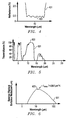
- Figure 3 is a plot of wavelength band versus reflectance for the signature of Figure 1.
- Figure 4 is an alternative plot of wavelength band versus reflectance for the signature of Figure 1 .
- Figure 5 is a plot of a wavelength band versus atmospheric transmittance for the signature of Figure 1 .
- Figure 6 is a plot of a wavelength band versus spectral radiant exitance for blackbody radiation of the signature of Figure 1 .
- Figure 7 is a plot of a wavelength band versus spectral radiant exitance for a hyper-spectral design of the signature of Figure 1 .
- Figure 8 is a plan view of an alternate embodiment of a signature constructed in accordance with the present invention.
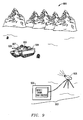
- Figure 9 is a schematic, operational diagram of a passive identification system constructed in accordance with the present invention.
- the signature 101 is part of a system that is designed to reflect light, such as infrared light, at very limited wavelengths in order to remotely identify an object.
- Signature 101 comprises a laminate of materials having a substrate 103, such as Mylar, and a thin film 105 mounted on a surface of the substrate 103.
- the thin film 105 may comprise a dielectric, vapor-deposited, multilayer laminate.
- the thin film 105 comprises a plurality of layers 107 having a high index of refraction that are interleaved with a plurality of layers 109 having a low index of refraction.
- Each of the layers 107, 109 has a thickness of one-quarter wavelength, other than a center, high index layer 111, which has a thickness of one-half wavelength.
- Figure 3 depicts a plot 301 of wavelength band versus reflectance for the signature 101 of Figure 1 .
- the value of the reflectance of the wavelength band is dependent upon the number of layers 107, 109, 111 in the signature 101, as described above.
- the peak reflectance 303 may range from 50 to 100% reflectance, as compared to the reflectance 305 of the structure on which signature 101 is located, which may only have a value of approximately 10% reflectance.
- Figure 4 depicts an alternative configuration or plot 401 of wavelength band versus reflectance for signature 101.
- Plot 401 illustrates the effect of the quarter-wave stack design of the thin film 105 ( Figure 2 ) on reflectance.
- signature may be configured with an unusually low reflectance (valley 403) on the order of only one-half percent (0.5%) reflectance as compared to the relatively higher reflectance of approximately 10% of the structure (see Figure 3 ) on which signature 101 is located.
- Figure 5 depicts a plot 501 of wavelength versus percentage of atmospheric transmittance (smoothed) for signature 101.
- the portion 503 of plot 501 illustrates the transmittance of thin film 105.
- Figure 6 is a plot 601 of a wavelength band versus spectral radiant exitance for blackbody radiation of signature 101.
- Figure 7 depicts a plot 701 of wavelength versus spectral radiant exitance for a hyper-spectral design of the signature 101 of Figure 1.
- the portions 703 of plot 701 illustrate multiple absorption lines having very narrow, half-wave bandwidths.
- Prior art detectors or sensors, which utilize "band averaging" techniques, are unable to detect these very narrowly separated absorption lines.
- Figure 8 is a plan view of an alternate embodiment of a signature 801 constructed in accordance with the present invention.
- Signature 801 is somewhat analogous to a bar code configuration. Although signature 801 is invisible to the naked eye, it can be detected and identified remotely at great distances when applied to an exterior surface of an object.
- Figure 9 is a schematic, operational diagram of a passive identification system 901 constructed in accordance with the present invention.
- the system 901 is designed to passively and remotely identify objects 907 with appropriate software.
- the system 901 identifies objects such as equipment, airborne aircraft, grounded aircraft, tanks, etc.
- the system 901 is also capable of tracking engagements of the objects and movement of supplies to and from the objects in real-time.
- the system 901 utilizes a series of signatures 909, which may comprise signatures 101, 801 (described above).
- the signatures 909 are positioned on exterior surfaces of a plurality of the objects 907.
- each of the signatures 909 has an encoded, two-dimensional, reflective configuration that is spectrally tailored to define a unique signature for each of the objects 907.
- a material used to form the reflective surfaces of the signatures 909 only reflects energy in wavelength band widths of approximately one-half wavelength.
- the signatures 909 may utilize patterns and symbols to further distinguish between the objects 907.
- the signatures 909 may be, for example, painted on the objects 907, and/or adhered to the objects 907 as appliqué.
- the signatures 909 are invisible to the naked human eye such that no intuitive knowledge can be gained by human observation of the signatures 909.
- the system 901 also comprises an optical imaging system 903 for remotely and passively detecting and decoding the signatures 909 and thereby identifying the objects 907 based on the signatures 909.
- a portion of the optical imaging system 903 may utilize existing sensors 908, such as those known in the art.
- the optical imaging system 903 has a scanning system 905 that passively records the light, such as infrared light, emanating from the signatures 909 in respective, specific wavelength bands.
- the optical imaging system 903 recognizes the signatures 909 to discern what the objects 907 are based on a database of information in the software.
- the wavelength bands are encoded to lie outside of threat bands of hostile detectors and hostile guided weapons.
- the scanning system 908 may be positioned remotely at ground-based, airborne, and/or satellite-based positions.
- the present invention has several advantages, including the ability to passively identify objects at large distances by utilizing an integrated, two-dimensional pattern, spectral tailoring, and an imaging system.
- This encoded information allows objects of various origin and configuration to be easily and rapidly identified by optical means.
- the present invention also track supplies while remaining invisible to the naked eye so that no intuitive knowledge can be gained by observing the information. This feature is particularly valuable with respect to low observable materials.
- Ground-based, airborne, or even satellite-based devices can be used to identify and track engagements of objects in real-time.
- a tailored reflective surface at a specific wavelength band is used to identify the objects.
- the material that forms the reflective surface only reflects energy in a very narrow wavelength band.
- the engineered material may be painted on an object or adhered to the object as a decal to provide the object with a unique signature.
- the signature is located on an exterior surface of the object and also may be formed in a particular pattern or symbol, such as a star or bars.
- the signatures are designed to be distinguishable from other signatures at great distances, and they do not lie in the threat zones of unauthorized detectors. Many different wavelength bands may be used to distinguish between different types of equipment.
- the system uses a database of information to passively record and recognize the light emanating from the signatures to discern the objects.
Landscapes
- Physics & Mathematics (AREA)
- General Physics & Mathematics (AREA)
- Engineering & Computer Science (AREA)
- Theoretical Computer Science (AREA)
- Investigating Or Analysing Materials By Optical Means (AREA)
- Image Input (AREA)
Applications Claiming Priority (2)
| Application Number | Priority Date | Filing Date | Title |
|---|---|---|---|
| US645029 | 1996-05-15 | ||
| US10/645,029 US7290710B2 (en) | 2003-08-21 | 2003-08-21 | System, method, and apparatus for passive, multi-spectral, optical identification of remote objects |
Publications (2)
| Publication Number | Publication Date |
|---|---|
| EP1517265A2 true EP1517265A2 (de) | 2005-03-23 |
| EP1517265A3 EP1517265A3 (de) | 2006-11-08 |
Family
ID=34194216
Family Applications (1)
| Application Number | Title | Priority Date | Filing Date |
|---|---|---|---|
| EP04254923A Withdrawn EP1517265A3 (de) | 2003-08-21 | 2004-08-17 | System, Verfahren und Vorrichtung zur passiven multispektralen optischen Identifikation entfernter Objekte |
Country Status (2)
| Country | Link |
|---|---|
| US (1) | US7290710B2 (de) |
| EP (1) | EP1517265A3 (de) |
Families Citing this family (2)
| Publication number | Priority date | Publication date | Assignee | Title |
|---|---|---|---|---|
| US8865293B2 (en) | 2008-12-15 | 2014-10-21 | 3M Innovative Properties Company | Optically active materials and articles and systems in which they may be used |
| US8102306B2 (en) | 2010-05-13 | 2012-01-24 | The United States Of America As Represented By The Secretary Of The Navy | Active-radar-assisted passive composite imagery for aiding navigation or detecting threats |
Family Cites Families (9)
| Publication number | Priority date | Publication date | Assignee | Title |
|---|---|---|---|---|
| US3936822A (en) * | 1974-06-14 | 1976-02-03 | Hirschberg Kenneth A | Method and apparatus for detecting weapon fire |
| US5734343A (en) | 1996-07-18 | 1998-03-31 | Motorola, Inc. | One-way optical highway communication system |
| US6215731B1 (en) * | 1997-04-30 | 2001-04-10 | Thomas Smith | Acousto-optic weapon location system and method |
| US6621764B1 (en) * | 1997-04-30 | 2003-09-16 | Thomas Smith | Weapon location by acoustic-optic sensor fusion |
| US6142372A (en) * | 1998-09-17 | 2000-11-07 | Wright; John E. | Tractor/trailer having bar code thereon and a GPS receiver for tracking and logging purposes |
| US6874639B2 (en) | 1999-08-23 | 2005-04-05 | Spectra Systems Corporation | Methods and apparatus employing multi-spectral imaging for the remote identification and sorting of objects |
| US6806480B2 (en) | 2000-06-30 | 2004-10-19 | David Reshef | Multi-spectral products |
| JP2002265004A (ja) * | 2001-03-08 | 2002-09-18 | Nisscom Corp | 産業廃棄物の最終処分場搬入管理システム |
| US6832728B2 (en) * | 2001-03-26 | 2004-12-21 | Pips Technology, Inc. | Remote indicia reading system |
-
2003
- 2003-08-21 US US10/645,029 patent/US7290710B2/en not_active Expired - Lifetime
-
2004
- 2004-08-17 EP EP04254923A patent/EP1517265A3/de not_active Withdrawn
Also Published As
| Publication number | Publication date |
|---|---|
| EP1517265A3 (de) | 2006-11-08 |
| US20050040245A1 (en) | 2005-02-24 |
| US7290710B2 (en) | 2007-11-06 |
Similar Documents
| Publication | Publication Date | Title |
|---|---|---|
| CA2189377C (en) | Active cooperative tuned identification friend or foe (actiff) | |
| US8033450B2 (en) | Expression codes for microparticle marks based on signature strings | |
| AU2002362643B2 (en) | Article with retroreflective and radio frequency-responsive features | |
| EP3317624B1 (de) | Optisches identifizierungs- und charakterisierungssystem und tags | |
| US6758405B2 (en) | Article with retroreflective and radio frequency-responsive features | |
| US20050195386A1 (en) | Object identification using quantum dots fluorescence allocated on fraunhofer solar spectral lines | |
| US20090040025A1 (en) | Radio Frequency Identification Interrogation Systems and Methods of Operating The Same | |
| WO1997011353A1 (en) | Target detection system utilizing multiple optical criteria | |
| US4797683A (en) | Multi-spectral radome | |
| KR20150093719A (ko) | 플랫폼에 장착된 카메라를 위한 보호 하우징 | |
| US11500138B2 (en) | Retroreflecting article with contrast reduction layer | |
| US7290710B2 (en) | System, method, and apparatus for passive, multi-spectral, optical identification of remote objects | |
| WO2006016094A1 (en) | Identification device and method | |
| US5093574A (en) | Infrared sensor for short range detection wherein the sun may be in the field of view of the detector | |
| US20110188707A1 (en) | System and Method for Pleographic Subject Identification, Targeting, and Homing Utilizing Electromagnetic Imaging in at Least One Selected Band | |
| US7965219B1 (en) | Patterned optical material and metamaterial for protection from and defeat of directed energy | |
| US9748643B2 (en) | Identification or messaging systems and related methods | |
| KR20240143802A (ko) | 다중 및 광대역 스텔스 구조체 | |
| US7920049B2 (en) | Registered 3-D optical thinfilm for remote identification | |
| US7276699B2 (en) | Absorptance enhancing coating for MWIR detectors | |
| US20040065850A1 (en) | Thermal imaging identification signage | |
| US20170016977A1 (en) | System and method for providing remote target identification using radiofrequency identification | |
| US8947204B1 (en) | Optical interrogation and registration system | |
| WO2017163057A1 (en) | Filter system | |
| EP2320521A1 (de) | Verfahren zum gesteuerten Reflektieren von Radarsignalen mittels Reflektionselementen |
Legal Events
| Date | Code | Title | Description |
|---|---|---|---|
| PUAI | Public reference made under article 153(3) epc to a published international application that has entered the european phase |
Free format text: ORIGINAL CODE: 0009012 |
|
| AK | Designated contracting states |
Kind code of ref document: A2 Designated state(s): AT BE BG CH CY CZ DE DK EE ES FI FR GB GR HU IE IT LI LU MC NL PL PT RO SE SI SK TR |
|
| AX | Request for extension of the european patent |
Extension state: AL HR LT LV MK |
|
| PUAL | Search report despatched |
Free format text: ORIGINAL CODE: 0009013 |
|
| AK | Designated contracting states |
Kind code of ref document: A3 Designated state(s): AT BE BG CH CY CZ DE DK EE ES FI FR GB GR HU IE IT LI LU MC NL PL PT RO SE SI SK TR |
|
| AX | Request for extension of the european patent |
Extension state: AL HR LT LV MK |
|
| 17P | Request for examination filed |
Effective date: 20070502 |
|
| AKX | Designation fees paid |
Designated state(s): DE FR GB IT |
|
| 17Q | First examination report despatched |
Effective date: 20070621 |
|
| STAA | Information on the status of an ep patent application or granted ep patent |
Free format text: STATUS: THE APPLICATION IS DEEMED TO BE WITHDRAWN |
|
| 18D | Application deemed to be withdrawn |
Effective date: 20110301 |