EP1517134A1 - Drug screening method and device using a Nipkow confocal scanner - Google Patents
Drug screening method and device using a Nipkow confocal scanner Download PDFInfo
- Publication number
- EP1517134A1 EP1517134A1 EP04020880A EP04020880A EP1517134A1 EP 1517134 A1 EP1517134 A1 EP 1517134A1 EP 04020880 A EP04020880 A EP 04020880A EP 04020880 A EP04020880 A EP 04020880A EP 1517134 A1 EP1517134 A1 EP 1517134A1
- Authority
- EP
- European Patent Office
- Prior art keywords
- cell
- image
- screening device
- section
- new drug
- Prior art date
- Legal status (The legal status is an assumption and is not a legal conclusion. Google has not performed a legal analysis and makes no representation as to the accuracy of the status listed.)
- Granted
Links
Images




Classifications
-
- G—PHYSICS
- G01—MEASURING; TESTING
- G01N—INVESTIGATING OR ANALYSING MATERIALS BY DETERMINING THEIR CHEMICAL OR PHYSICAL PROPERTIES
- G01N33/00—Investigating or analysing materials by specific methods not covered by groups G01N1/00 - G01N31/00
- G01N33/48—Biological material, e.g. blood, urine; Haemocytometers
- G01N33/50—Chemical analysis of biological material, e.g. blood, urine; Testing involving biospecific ligand binding methods; Immunological testing
- G01N33/5005—Chemical analysis of biological material, e.g. blood, urine; Testing involving biospecific ligand binding methods; Immunological testing involving human or animal cells
- G01N33/5008—Chemical analysis of biological material, e.g. blood, urine; Testing involving biospecific ligand binding methods; Immunological testing involving human or animal cells for testing or evaluating the effect of chemical or biological compounds, e.g. drugs, cosmetics
- G01N33/502—Chemical analysis of biological material, e.g. blood, urine; Testing involving biospecific ligand binding methods; Immunological testing involving human or animal cells for testing or evaluating the effect of chemical or biological compounds, e.g. drugs, cosmetics for testing non-proliferative effects
-
- G—PHYSICS
- G01—MEASURING; TESTING
- G01N—INVESTIGATING OR ANALYSING MATERIALS BY DETERMINING THEIR CHEMICAL OR PHYSICAL PROPERTIES
- G01N21/00—Investigating or analysing materials by the use of optical means, i.e. using sub-millimetre waves, infrared, visible or ultraviolet light
- G01N21/62—Systems in which the material investigated is excited whereby it emits light or causes a change in wavelength of the incident light
- G01N21/63—Systems in which the material investigated is excited whereby it emits light or causes a change in wavelength of the incident light optically excited
- G01N21/64—Fluorescence; Phosphorescence
- G01N21/6408—Fluorescence; Phosphorescence with measurement of decay time, time resolved fluorescence
-
- G—PHYSICS
- G01—MEASURING; TESTING
- G01N—INVESTIGATING OR ANALYSING MATERIALS BY DETERMINING THEIR CHEMICAL OR PHYSICAL PROPERTIES
- G01N21/00—Investigating or analysing materials by the use of optical means, i.e. using sub-millimetre waves, infrared, visible or ultraviolet light
- G01N21/62—Systems in which the material investigated is excited whereby it emits light or causes a change in wavelength of the incident light
- G01N21/63—Systems in which the material investigated is excited whereby it emits light or causes a change in wavelength of the incident light optically excited
- G01N21/64—Fluorescence; Phosphorescence
- G01N21/6428—Measuring fluorescence of fluorescent products of reactions or of fluorochrome labelled reactive substances, e.g. measuring quenching effects, using measuring "optrodes"
-
- G—PHYSICS
- G01—MEASURING; TESTING
- G01N—INVESTIGATING OR ANALYSING MATERIALS BY DETERMINING THEIR CHEMICAL OR PHYSICAL PROPERTIES
- G01N21/00—Investigating or analysing materials by the use of optical means, i.e. using sub-millimetre waves, infrared, visible or ultraviolet light
- G01N21/62—Systems in which the material investigated is excited whereby it emits light or causes a change in wavelength of the incident light
- G01N21/63—Systems in which the material investigated is excited whereby it emits light or causes a change in wavelength of the incident light optically excited
- G01N21/64—Fluorescence; Phosphorescence
- G01N21/645—Specially adapted constructive features of fluorimeters
- G01N21/6452—Individual samples arranged in a regular 2D-array, e.g. multiwell plates
-
- G—PHYSICS
- G01—MEASURING; TESTING
- G01N—INVESTIGATING OR ANALYSING MATERIALS BY DETERMINING THEIR CHEMICAL OR PHYSICAL PROPERTIES
- G01N21/00—Investigating or analysing materials by the use of optical means, i.e. using sub-millimetre waves, infrared, visible or ultraviolet light
- G01N21/62—Systems in which the material investigated is excited whereby it emits light or causes a change in wavelength of the incident light
- G01N21/63—Systems in which the material investigated is excited whereby it emits light or causes a change in wavelength of the incident light optically excited
- G01N21/64—Fluorescence; Phosphorescence
- G01N21/645—Specially adapted constructive features of fluorimeters
- G01N21/6456—Spatial resolved fluorescence measurements; Imaging
- G01N21/6458—Fluorescence microscopy
-
- G—PHYSICS
- G01—MEASURING; TESTING
- G01N—INVESTIGATING OR ANALYSING MATERIALS BY DETERMINING THEIR CHEMICAL OR PHYSICAL PROPERTIES
- G01N33/00—Investigating or analysing materials by specific methods not covered by groups G01N1/00 - G01N31/00
- G01N33/48—Biological material, e.g. blood, urine; Haemocytometers
- G01N33/50—Chemical analysis of biological material, e.g. blood, urine; Testing involving biospecific ligand binding methods; Immunological testing
- G01N33/5005—Chemical analysis of biological material, e.g. blood, urine; Testing involving biospecific ligand binding methods; Immunological testing involving human or animal cells
- G01N33/5008—Chemical analysis of biological material, e.g. blood, urine; Testing involving biospecific ligand binding methods; Immunological testing involving human or animal cells for testing or evaluating the effect of chemical or biological compounds, e.g. drugs, cosmetics
-
- G—PHYSICS
- G02—OPTICS
- G02B—OPTICAL ELEMENTS, SYSTEMS OR APPARATUS
- G02B21/00—Microscopes
- G02B21/0004—Microscopes specially adapted for specific applications
- G02B21/002—Scanning microscopes
- G02B21/0024—Confocal scanning microscopes (CSOMs) or confocal "macroscopes"; Accessories which are not restricted to use with CSOMs, e.g. sample holders
- G02B21/0036—Scanning details, e.g. scanning stages
- G02B21/0044—Scanning details, e.g. scanning stages moving apertures, e.g. Nipkow disks, rotating lens arrays
-
- G—PHYSICS
- G02—OPTICS
- G02B—OPTICAL ELEMENTS, SYSTEMS OR APPARATUS
- G02B21/00—Microscopes
- G02B21/0004—Microscopes specially adapted for specific applications
- G02B21/002—Scanning microscopes
- G02B21/0024—Confocal scanning microscopes (CSOMs) or confocal "macroscopes"; Accessories which are not restricted to use with CSOMs, e.g. sample holders
- G02B21/0052—Optical details of the image generation
- G02B21/0076—Optical details of the image generation arrangements using fluorescence or luminescence
Definitions
- the present invention relates to a screening method and device used in the discovery of a drug, or drug discovery for developing a new kind of medical product, and so on.
- a device for screening a cell processed by a fluorescent reagent, and so on, and described in International Patent Publication No. 2002-525603 (International Laid-Open No. WO00/17643) is well known as a screening device of this kind.
- Fig. 1 is a constructional view of the screening device described in patent literature 1.
- This device uses a standard objective lens having a magnification power of 1 to 100 in comparison with a camera lens, and an inverted type fluorescent microscope 1 such as a Zeiss Axiovert inverted type fluorescent microscope using a light source (e.g. a 100W mercury-arc lamp or 75W xenon lamp) with power source 2.
- XY stage 3 for moving plate 4 in the XY directions is arranged on the microscope objective lens.
- Plate 4 is a standard plate of 96 wells. A cell is inj ected into each well, and a reagent is added. After plate 4 is placed on microscope assembly 1, plate 4 is moved in the XY directions by XY stage 3. A fluorescent image emitted from the cell of each well is received by camera 7. An output signal of the camera is inputted to central processing unit 10, and is processed and displayed in a display format corresponding to the fluorescent image on display 12 of PC 11. Further, the record of a hard copy can be printed in printer 13.
- the operating effect of the reagent with respect to the cell can be detected.
- a Z-axis focal point driving mechanism 5 is a Z-axis direction moving mechanism for adjusting the focal point of the objective lens.
- Joystick 6 is used to manually move the stage in the XYZ directions.
- power source 8 for the camera, and automatic controller 9 are arranged.
- An object of the present invention is to solve such problems and provide a screening method and device able to obtain the entire image of the cell as a detailed and accurate (with a good SN ratio) image at high speed by observing the cell image while a Nipkow system confocal scanner is used and the focal position of the objective lens is changed in the optical axis direction.
- Another object of the present invention is to provide a screening device which, by reducing the amount of irradiating light of the excitation light, does not produce a negative influence by the excitation light on the cell.
- Another object of the present invention is to provide a new drug screening device able to observe the entire image of the cell with high resolution and a high degree of accuracy by observing the cell image while a Nipkow system confocal scanner is used and the focal position of the objective lens is changed in the optical axis direction, and able to judge the degree of activity of the cell from the obtained image, and display a judging result in an easily recognizable display format.
- Another object of the present invention is to provide a new drug screening device able to automatically inject the cell and the reagent into the well in accordance with a condition set in advance.
- Another object of the present invention is to provide a new drug screening device for calculating an optical flow from a time differential image by an arithmetic operation, and able to determine the degree of activity of the cell by making an inference for distinguishing circulatory activity within the cell and a Brownian movement on the basis of this calculation.
- Still another object of the present invention is to provide a new drug screening device able to simply mark a target well so as to easily find the optimum well, the worst well, and so on, from the plate after measurement.
- Another object of the present invention is to provide a new drug screening device having no negative influence by the excitation light on the cell by reducing the irradiating light amount.
- Another object of the present invention is to provide a new drug screening method and device able to grasp the effect of the reagent with respect to the cell by calculating the degree of activity (ADMETOX) of the cell on the basis of the fluorescent image of the cell, and judging whether this degree of activity is good or not.
- ADMETOX degree of activity
- another object of the present invention is to provide a new drug screening method and device for calculating the optical flow from the time differential image of the fluorescent image by an arithmetic operation, and determining the degree of activity of the cell by making the inference for distinguishing the circulatory activity within the cell and the Brownian movement on the basis of this calculation, and judging whether this degree of activity is good or not, and obtaining this judging result in the early stage of screening.
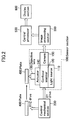
- Fig. 2 is a constructional view showing one embodiment of a screening device in the present invention.
- reference numerals 100, 200, and 300 designate a sensor section, a control mechanical section, and an image processing section respectively.
- Reference numerals 400, 500, and 600 designate a plate (corresponding to plate 4 of Fig. 1), a central processing unit, and a display section respectively.
- Sensor section 100 is constructed from laser light source 110, Nipkow system confocal scanner 120, objective lens 130, focal position variable means 140 and camera 150.
- a laser beam as excitation light generated from laser light source 110 is converged onto a sample of plate 400 by objective lens 130 through Nipkow system confocal scanner 120. Fluorescent light from the sample excited by the laser beam is returned to confocal scanner 120 via objective lens 130, and is inputted to camera 150. In camera 150, a fluorescent image of the XY plane of sample 401 is obtained. In this case, since a Nipkow system confocal scanner is used, a detailed and accurate (with a good SN ratio) image is obtained at high speed.
- Nipkow system confocal scanner 120 is constructed as shown in Fig. 3.
- Fig. 3 shows this construction in reverse relation to Fig. 2 with respect to the upper and lower portions.
- obj ective lens 130 and light receiving element 151 of camera 150 are shown together.
- laser beam 121 as the excitation light is converged to an individual light beam by each microlens 123 arranged in microlens disk 122.
- the laser beam After the laser beam is transmitted through dichroic mirror 124, the laser beam passes through individual pinhole 126 formed in pinhole disk (also called a Nipkow disk) 125 and is converged to sample 401 by objective lens 130.
- the fluorescent light generated from sample 401 again passes through objective lens 130, and is converged onto the individual pinhole of pinhole disk 125.
- the fluorescent light passing through individual pinhole 126 is reflected on dichroic mirror 124, and a fluorescent image is formed on light receiving element 151 of the camera by relay lens 129.
- Dichroic mirror 124 used here is designed so as to transmit excitation light 121 and reflect the fluorescent light from sample 401.
- Microlens disk 122 and pinhole disk 125 are mechanically connected by member 127, and are integrally rotated around rotating shaft 128. Individual microlens 123 and pinhole 126 are arranged such that the excitation light from individual pinhole 126 formed on pinhole disk 125 scans an observing plane of sample 401. Further, an arranging plane of pinhole 126, the observing plane of sample 401 and light receiving element 151 of the camera are mutually arranged in an optically conjugate relation. Therefore, an optical sectional image of sample 401, i.e. a confocal image is formed on light receiving element 151.
- focal position variable means 140 entirely operates objective lens 130 or sensor section 100, and continuously or discontinuously moves (hereinafter also termed scans) the focal position of objective lens 130 in the Z-axis direction (optical axis direction) .
- a Piezo actuator (simply called actuator) is used as focal position variable means 140.
- actuator an explanation will be given with the actuator as an example.
- Control mechanical section 200 performs an XYZ direction operation for arranging a substrate stage, not shown in the figure, placing plate 400 thereon in a predetermined position with respect to sensor section 100 and moving the substrate stage suitably in the XYZ directions so as to sequentially observe each well. Control mechanical section 200 also performs an XY direction operation for adjusting the XY direction positions of the sensor section.
- Image processing section 300 receives an image signal from camera 150, and performs suitable image processing and data processing for showing the degree of activity of a cell, and so on.
- the processing also includes processing for making a statistical analysis of the fluorescent strength of the cell, kinetics, a histogram, a correlation diagram, and so on.
- the processed image is displayed in display section 600 by central processing unit 500.
- Central processing unit 500 also appropriately controls the operations of control mechanical section 200, actuator 140 and image processing section 300.
- a sample i.e. a living cell and a fluorescent marked reagent, are respectively injected into each well of plate 400 in advance.
- Plate 400 is moved by control mechanical section 200 and is arranged in a predetermined position on sensor section 100.
- the sample is irradiated by the laser beam (excitation light) from sensor section 100, and fluorescent light is generated from the cell.
- This fluorescent light is formed as an image of confocal scanner 120 through objective lens 130 and actuator 140. This image (cell image) is read by camera 150.
- objective lens 130 is continuously or discontinuously scanned by actuator 140 in the Z-axis direction.
- a slice image of the cell is obtained at high speed, and the slice image of the cell in each different sectional position can be obtained from above to below in the Z-axis direction by camera 150.
- image processing section 300 predetermined image processing is performed on the basis of plural slice images obtained by camera 150, and images of the degree of activity, and so on, over the entire cell are obtained.
- processing for forming one two-dimensional image (overlapping image) from the plural slice images obtained by camera 150 by, for example, three-dimensional data processing, and classifying the image by color in accordance with the difference in the expression amount of fluorescent protein, and so on, are also performed. Further, Hough transform processing can be also included in the image processing.
- the image processed by image processing section 300 is stored to a memory means, not shown in the figure, as necessary, and is displayed in display section 600 by central processing unit 500.
- three-dimensional objective lens 130 is scanned in the Z-axis direction by Piezo actuator 140, but three-dimensional processing may be also performed using multiheads with far, mid- and close focal positions, and so on.
- the focal position of the objective lens with respect to the sample may be also moved by voltage control by inserting a varifocal lens of the voltage control between objective lens 130 and confocal scanner 120 without operating objective lens 130 with the Piezo actuator.
- excitation is performed by a laser beam
- fluorescent light may also be generated from the sample by utilizing 2-photon absorption and irradiating infrared light as the excitation light and causing 2-photon absorption.
- it is sufficient to irradiate the infrared light having reduced light energy to the cell so that the influence of light on the cell can be almost eliminated.
- the image of the sample may be also picked up by the camera by dyeing the cell using quantum dots, performing excitation with a short wavelength laser beam, and giving the filter of the camera spectroscopic characteristics with a discriminating function.
- sensitivity and discriminating ability can be easily improved.
- the Nipkow system confocal scanner's output image may also be detected by using a line sensor.
- a coincident property and a higher resolution property can be simultaneously achieved.
- a multicolor line sensor may be also used as the line sensor.
- An image (of a long focal depth corresponding to a scanning thickness which is called a long focal image) obtained by exposing sectional image information of the sample (cell) obtained by scanning the objective lens in the optical axis direction by a required depth within the same frame period of the camera may also be used as the image utilized in image processing section 300.
- Fig. 4 is a constructional view of another embodiment in the present invention. This new drug screening device realizes the following points.
- FIG. 4 An image processed by image processing section 300 is displayed in display section 600 by control section 500a.
- control section 500a which appropriately controls the operations of control mechanical section 200, actuator 140, image processing section 300, judging section 700 and dispenser 800.
- Dispenser 800 has a mechanism for respectively inj ecting the cell (a living cell fluorescent marked in advance) and the reagent into each well of plate 400 by using, for example, an electromagnetic pump, not shown in the figure, and so on, and performing the marking on the plate after the measurement.
- the reagent is not limited to one kind, but various kinds of reagents such as plural reagents, reagents of the same kind but of different densities, and so on, are applied appropriately.
- Dispenser 801 is used for the cell injection, and dispenser 802 is used to inject reagent A.
- Dispenser 803 is used to inject reagent B, and dispenser 804 is used for coating with colored paint for marking.
- the number of dispensers for the reagents and the paint are not limited to the embodiment.
- the cell and the reagent to be injected into each cell are set and stored in control section 500a in advance.
- the electromagnetic pumps of dispensers 801, 802, 803 are operated in accordance with this setting, and the cell and the reagent are automatically injected into each well of plate 400.
- plate 400 is automatically moved to a position corresponding to the injecting dispenser by control mechanical section 200 controlled by control section 500a.
- Judging section 700 has a function for determining the degree of activity of the cell by using data after image processing obtained by image processing section 300.
- a moving vector of fine particles is extracted from the differential image between the image of time (t) and the image of time (t+ ⁇ t) after a certain time has passed. Every ⁇ t in the whole flow of this vector is called an optical flow.
- this optical flow is set to one direction.
- the flow direction is random and no movement is made at a long distance even when the movement is integrated.
- Judging section 700 has an inferential portion (AI inferential engine) assembling a program for distinguishing the circulatory activity within the cell and the Brownian movement on the basis of the optical flow calculated from the time differential image.
- AI inferential engine AI inferential engine
- the degree of activity of the cell can be judged without error.
- the speed of the plasma streaming has a good relation with the degree of activity and a rapid judgment can be made in the early stage of screening.
- judging section 700 can also perform an output operation in a display format easily discriminated in the display section by adding a mark classified by color and corresponding to an adopted or rej ected selection or the degree of activity in each well in accordance with the degree of activity, and so on.
- the cell and the reagent are injected into each cell of plate 400 from the dispenser in accordance with information set to control section 500a in advance.
- dispenser 800 and plate 400 are operated by control mechanical section 200 in accordance with the instructions of control section 500a, and are moved relatively.
- plate 400 After the injection into the well, plate 400 is arranged in a predetermined position on sensor section 100 by operating control mechanical section 200.
- the sample of the well is irradiated by a laser beam (excitation light) from sensor section 100, and fluorescent light is generated from the cell.
- This fluorescent light passes through objective lens 130 and actuator 140 and is formed as an image on confocal scanner 120.
- This image (cell image) is then read by camera 150.
- objective lens 130 is continuously or discontinuously scanned by actuator 140 in the Z-axis direction.
- a slice image of the cell is obtained by camera 150 in each different sectional position from above to below in the Z-axis direction.
- Each slice image obtained by the confocal scanner is a detailed and accurate image having a good SN ratio.
- a Nipkow system confocal scanner is used as the confocal scanner, a detailed and accurate image having a good SN ratio can be obtained at higher speed.
- the image is similarly measured with respect to each well. This image measurement is made at a predetermined time interval.
- Image processing section 300 obtains an image of a super depth, in which the image in the depth direction of the cell is clearly and accurately displayed using plural slice images obtained by camera 150.
- This image is a fluorescent image in which a moving mode of the entire cell is more accurately grasped in comparison with a defocused image using the conventional fluorescent microscope irrespective of the dispersion of each cell in the Z-axis direction within the well.
- These image data can be appropriately stored to a memory means, which is not shown in the figure.
- Hough transform may also be used in the image processing. Further, a super depth fluorescent image may be photographed by camera 150 by continuously scanning actuator 140 in the Z-axis direction.
- Judging section 700 calculates the optical flow by the AI inferential engine from the differential image between the image of time (t) and the image of time (t+ ⁇ t) after a certain time has passed. Judging section 700 then judges the degree of activity of the cell. Judging section 700 further outputs data of the display format, easily discriminated by adding a mark classified by color according to the degree of activity of each well, and so on. Further, judging section 700 also outputs information as to which well is the optimum well and the worst well.
- the judging result in judging section 700 is displayed in display section 600.
- the judging result can be stored to a memory means, not shown in the figure, as necessary.
- Control section 500a can display information such as the injecting condition of the well, for example, the kind and the density of the cell, and the reagent injected into each well, and so on, in display section 600 together with the above judging result.
- control section 500a only a target well of plate 400 after the measurement is marked by operating dispenser 804 for marking and control mechanical section 200 on the basis of the judging result of judging section 700.
- colored paint is attached to the vicinity of the target well of the plate surface by dispenser 804.
- the next embodiment shows a new drug screening method and device for solving the following problems.
- the embodiment of this invention has the following points as objects to solve such problems.
- the effect of the reagent with respect to the cell can be grasped by calculating the degree of activity (ADMETOX) of the cell on the basis of the fluorescent image of the cell and judging whether this degree of activity is good or not.
- the optical flow is calculated from the time differential image of the fluorescent image by an arithmetic operation, and the degree of activity of the cell is determined by making an inference for distinguishing the circulatory activity within the cell and the Brownian movement on the basis of this calculation, and it is judged whether the degree of activity is good or not, and the result of this judgment is obtained in the early stage of screening.
- judging section 700 has a function for determining the degree of activity of the cell by using image data obtained in image processing section 300. Judging section 700 of this embodiment further judges whether the degree of activity calculated in this way is good or not.
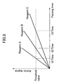
- Fig. 5 schematically shows a time change of the degree of activity of the cell due to a difference in the kind of reagent. The axis of abscissa shows a passing time, and the axis of ordinate shows the degree of activity.
- line A shows the time change in the degree of activity of the cell of a well into which reagent A has been injected.
- Line B shows the time change in the degree of activity of the cell of a well into which reagent B has been injected.
- Line C shows the time change in the degree of activity of the cell of a well into which reagent C has been inj ected.
- the time change in the degree of activity is different depending on the kind of reagent.
- Such characteristics of degree of activity are also different depending on the density of the reagent.
- Judging section 700 applies a certain threshold value to such a degree of activity and judges whether the degree of activity of the cell is good or not, in other words, whether the effect of the reagent with respect to the cell is good or bad according to whether the degree of activity is the threshold value or more, or the threshold value or less.
- Judging section 700 sets the degree of activity of the well by for example, a maximum value or an average value of the degree of activity of each cell, and judges whether the degree of activity is good or not.
- the judging result as to whether the degree of activity is good or not is outputted by adding the information of a display color corresponding to the goodness to the judging result so as to easily identify it. For example, the judging result is outputted by adding red information to the well having a degree of activity of the threshold value or more.
- the judging result can be stored to a memory means, not shown in the figure, as necessary.
- display section 600 displays the judging result of the degree of activity with respect to each well 402 of plate 400.
- reagents A, B and C shown in Fig. 5 are inj ected into the first, second and third columns from the left.
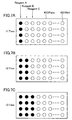
- Figs. 7A, 7B and 7C show display examples of the respective judging results at times t1, t2, t3 of Fig. 3.
- the wells of the threshold value or more in the degree of activity are shown by black circles.
- Fig. 7 shows the display examples of the judging result when the density is different in accordance with each reagent.
- Fig. 7 shows a case in which the density sequentially becomes thin from the upper side to the lower side.
- the degree of activity may also be judged to be good or not by using two threshold values or more.
- image processing section 300 The operations until image data are obtained in image processing section 300, are equal to those in the above embodiment. Therefore, their explanations are omitted here.
- image data processed by image processing section 300 are transmitted to judging section 700.
- Judging section 700 calculates the optical flow by the AI inferential engine from the differential image between the image of time (t) and the image of time (t+ ⁇ t) after a certain time has passed. Judging section 700 then calculates the degree of activity of the cell for each well.
- judging section 700 judges whether the degree of activity of the cell is good or not for each well with a certain threshold value as a reference. In other words, the effect of the reagent with respect to the cell. With respect to the degree of activity of the threshold value or more, it is judged as good, and the judging result is outputted by adding, for example, red display color information.
- Fig. 7 The judging result is displayed in the format as shown in Fig. 7 in display section 600. In this figure, wells judged as good in the degree of activity are displayed in black.
- Figs. 7A, 7B and 7C display the respective judging results at times t1, t2, t3 corresponding to Fig. 5.
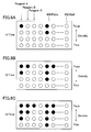
- Fig. 8 shows a display pattern example of the judging result when the reagent of a different kind is simply injected to every column of the well.
- the display pattern becomes more complicated when a reagent of a different kind and density is injected into each cell.
- Control section 500a can display information the injecting condition of the well, for example, the kinds, the densities, and so on, of the cell and the reagent injected into each well in display section 600 together with the display of the above judging result. Thus, whether the degree of activity of the cell is good or not for each well is automatically judged, and the judging result can be displayed in an easily recognizable display format.
- control section 500a only a target well of plate 400 after the measurement is marked by operating dispenser 804 for marking and control mechanical section 200 on the basis of the judging result of judging section 700.
- colored paint is attached to the vicinity of the target well on the plate surface.
- the dispenser may be also operated at high speed by using the Piezo actuator instead of the electromagnetic pump.
- the number of plates 400 is not limited to one, but setting of the injecting condition, the observation and the judgment can be made continuously with respect to plural plates of conditions different from each other.
- image processing section 300 and judging section 700 are shown as independent constructional elements in the drawings, but may also be constructed so as to be included in control section 500a.
- three-dimensional objective lens 130 is scanned in the Z-axis direction by Piezo actuator 140, but three-dimensional processing may also be performed by using multiheads with far, mid- and close focal positions, and so on.
- the focal position of the objective lens with respect to the sample may also be varied by voltage control by inserting a varifocal lens of a voltage control type between objective lens 130 and confocal scanner 120 without operating objective lens 130 by the Piezo actuator.
- the excitation is performed by the laser beam, but fluorescent light may be also generated from the sample by utilizing 2-photon absorption, irradiating infrared light as the excitation light and causing the 2-photon absorption.
- fluorescent light may be also generated from the sample by utilizing 2-photon absorption, irradiating infrared light as the excitation light and causing the 2-photon absorption.
- it is sufficient to irradiate the infrared light having reduced light energy to the cell so that the influence of the light on the cell can be almost removed.
- the image of the sample may also be picked up by the camera by dyeing the cell using quantum dots, and exciting them by a short wavelength laser beam using a camera filter provided with spectroscopic characteristics having a discriminating function.
- sensitivity and discriminating ability can be easily improved.
- the output image of the Nipkow system confocal scanner may also be detected by using a line sensor.
- a coincident property and a higher resolution property can be simultaneously achieved.
- a multicolor line sensor may be also used as the line sensor.
- the living cell is observed intermittently over a long time by the confocal scanner, and the active state of the cell can be also trend-displayed.
- An image (an image of long focal depth corresponding to a scanning thickness which is called a long focal image) obtained by exposing sectional image information of the sample (cell) obtained by scanning the objective lens in the optical axis direction by a required depth within the same frame period of the camera may be also used as the image utilized in image processing section 300.
- the degree of activity can be rapidly judged in the early stage of screening, and screening can be performed easily at high speed.
Landscapes
- Health & Medical Sciences (AREA)
- Life Sciences & Earth Sciences (AREA)
- Immunology (AREA)
- Chemical & Material Sciences (AREA)
- Engineering & Computer Science (AREA)
- Physics & Mathematics (AREA)
- Pathology (AREA)
- Biomedical Technology (AREA)
- General Physics & Mathematics (AREA)
- General Health & Medical Sciences (AREA)
- Biochemistry (AREA)
- Analytical Chemistry (AREA)
- Molecular Biology (AREA)
- Hematology (AREA)
- Nuclear Medicine, Radiotherapy & Molecular Imaging (AREA)
- Urology & Nephrology (AREA)
- Biotechnology (AREA)
- Medicinal Chemistry (AREA)
- Cell Biology (AREA)
- Food Science & Technology (AREA)
- Tropical Medicine & Parasitology (AREA)
- Toxicology (AREA)
- Bioinformatics & Cheminformatics (AREA)
- Microbiology (AREA)
- Chemical Kinetics & Catalysis (AREA)
- Optics & Photonics (AREA)
- Investigating Or Analysing Biological Materials (AREA)
Abstract
Description
It is to be understood that the present invention is not restricted to the foregoing embodiments, rather, many other alterations and modifications thereof may be made without departing from the spirit and essential characteristics thereof.
A moving vector of fine particles is extracted from the differential image between the image of time (t) and the image of time (t+Δt) after a certain time has passed. Every Δt in the whole flow of this vector is called an optical flow. In the case of plasma streaming, this optical flow is set to one direction. In the case of the Brownian movement, the flow direction is random and no movement is made at a long distance even when the movement is integrated.
Claims (34)
- A screening method in which a reagent and a fluorescent marked cell are injected into a well, and
a Nipkow system confocal scanner is used, a focal position is changed in the direction of an optical axis, excitation light is irradiated to said well in each focal position, fluorescent light generated from the cell is received and the degree of activity, and so on, of the cell is measured on the basis of a slice image of the cell. - The screening method according to claim 1, wherein the degree of activity, and so on, of the cell is measured on the basis of plural slice images or long focal images.
- A screening device which comprises a sensor section for preparing a plate constructed by injecting a reagent and a fluorescent marked cell into plural wells, and irradiating excitation light to said wells and obtaining a fluorescent image of the cell by receiving fluorescent light generated from the cell; an image processing section for performing suitable processing with respect to a fluorescent image signal from this sensor section; and a display section for displaying an output of this image processing section; and observes a dynamic mode of the cell, and so on; wherein
said sensor section includes a Nipkow system confocal scanner, an objective lens, focal position variable means for moving the focal position of this objective lens in the optical axis direction, and a camera for taking an output image of said confocal scanner, and is constructed such that the focal position of the objective lens is moved by said focal position variable means in the optical axis direction, and excitation light is irradiated from the confocal scanner to said cell through the objective lens in each focal position, and plural different slice images are obtained in the optical axis direction of the cell. - The screening device according to claim 3, wherein said image processing section has a function for calculating the image of the cell on the basis of said plural slice images or long focal images.
- The screening device according to claim 3, wherein the focal position variable means of said sensor section moves the entire objective lens or sensor section in the optical axis direction.
- The screening device according to claim 5, wherein the focal position variable means of said sensor section uses a Piezo actuator.
- The screening device according to claim 3, wherein said sensor section moves the focal position by using multiheads of focal positions different from each other and switching said multiheads.
- The screening device according to claim 3, wherein said sensor section generates the fluorescent light from said cell by using infrared light as the excitation light and causing 2-photon absorption.
- The screening device according to claim 3, wherein the cell injected into said well is dyed by using quantum dots in advance, and
said sensor section is constructed such that a short wavelength laser beam is irradiated to said cell and the output image of the confocal scanner is picked up by the camera through a filter provided with spectroscopic characteristics having a discriminating function . - The screening device according to claim 3, wherein said sensor section is constructed so as to detect the output image of said confocal scanner by using a line sensor.
- A new drug screening device which comprises a dispenser for injecting a reagent and a fluorescent marked cell into plural wells of a plate; a sensor section for irradiating excitation light to said well and obtaining a fluorescent image of the cell by receiving fluorescent light generated from the cell; an image processing section for performing suitable processing with respect to a fluorescent image signal from this sensor section; a judging section for judging the degree of activity of the cell on the basis of an output image of this image processing section; a display section for displaying results of this judging section; a mechanical control section for moving said plate and the sensor section and controlling these movements; and a control section for setting a condition and controlling the operation of each section; and observes a dynamic mode, and so on, of the cell; wherein
said sensor section includes a Nipkow system confocal scanner, an objective lens, focal position variable means for moving the focal position of said objective lens in the optical axis direction, and a camera for picking-up an output image of said confocal scanner, and is constructed such that excitation light is irradiated from the confocal scanner to said cell through said objective lens and a slice image of the cell is obtained while the focal position of said objective lens is moved by said focal position variable means in the optical axis direction; and
said control section has a function for respectively injecting the cell and the reagent into the plural wells by operating said dispenser on the basis of conditions set in advance. - The new drug screening device according to claim 11, wherein said image processing section has a function for calculating the image of the cell on the basis of said plural slice images or long focal images by three-dimensional data processing.
- The new drug screening device according to claim 11, wherein said judging section has an inferential portion for distinguishing circulatory activity within the cell and a Brownian movement on the basis of an optical flow calculated from a time differential image, and also has a function for determining the degree of activity of the cell.
- The new drug screening device according to claim 11, wherein the new drug screening device further comprises a dispenser for attaching colored paint to said plate, and
the new drug screening device is constructed such that only a target well is marked by this dispenser on the basis of the judging result of said judging section. - The new drug screening device according to claim 11, wherein the focal position variable means of said sensor section is constructed so as to move the entire objective lens or sensor section in the optical axis direction.
- The new drug screening device according to claim 15, wherein the focal position variable means of said sensor section uses a Piezo actuator in the movement in the optical axis direction.
- The new drug screening device according to claim 11, wherein said sensor section switches the focal position by using multiheads of focal positions different from each other and switching said multiheads.
- The new drug screening device according to claim 11, wherein said sensor section generates the fluorescent light from said cell by using infrared light as the excitation light and causing 2-photon absorption.
- The new drug screening device according to claim 11, wherein the cell injected into said well is dyed by using quantum dots in advance, and
said sensor section is constructed such that a short wavelength laser beam is irradiated to said cell and the output image of the confocal scanner is picked up by the camera through a filter provided with spectroscopic characteristics having a discriminating function . - The new drug screening device according to claim 11, wherein said sensor section is constructed so as to detect the output image of said confocal scanner by using a line sensor.
- A new drug screening method in which a reagent and a fluorescent marked cell are injected into plural wells on a plate, a fluorescent image generated from the cell is read for each well, the degree of activity of the cell is calculated on the basis of said fluorescent image, whether the degree of activity of the cell is good or not is judged for each well, and the effects of said reagent with respect to the cell can be confirmed on the basis of this judgment.
- The new drug screening method according to claim 21, wherein the judging result of the degree of activity of each said well is classified by color and displayed.
- The new drug screening method according to claim 21, wherein an optical flow is calculated by an arithmetic operation from a time differential image of the fluorescent image generated from said cell and the degree of activity of said cell is calculated from circulatory activity within the cell obtained on the basis of this optical flow.
- A new drug screening device comprising:a dispenser for injecting a reagent and a fluorescent marked cell into plural wells of a plate;an image processing section for calculating the degree of activity of the cell on the basis of a fluorescent image from the cell obtained by irradiating excitation light to said well;a judging section for partitioning the degree of activity of said cell by a certain threshold value and judging whether this degree of activity is good or not with respect to each said well; anda display section for displaying the judging result of said degree of activity with respect to each well; whereinthe new drug screening device is constructed so as to grasp the effects of the reagent from the judging result of the degree of activity of said cell.
- The new drug screening device according to claim 24, wherein said display section is constructed such that the degree of activity of each said well is classified by color and displayed in a display color corresponding to said judging result.
- The new drug screening device according to claim 24, wherein said judging section has an inferential portion for distinguishing circulatory activity within the cell and a Brownian movement on the basis of an optical flow calculated from a time differential image, and also has a function for determining the degree of activity of the cell.
- The new drug screening device according to claim 24, wherein said dispenser has a dispenser for attaching colored paint onto said plate, and
the new drug screening device is constructed such that only a target well is marked by the dispenser for attaching said colored paint to the vicinity of this target well on the basis of the judging result of said judging section. - The new drug screening device according to claim 24, wherein the new drug screening device is constructed so as to obtain said fluorescent image by an objective lens, a Nipkow system confocal scanner for irradiating the excitation light to said well through said objective lens and obtaining the fluorescent image of the cell by receiving the fluorescent light generated from the cell, and a sensor section including a camera for taking an output image of said confocal scanner.
- The new drug screening device according to claim 24, wherein said sensor section is constructed so as to move the entire objective lens or sensor section in the optical axis direction and obtain plural slice images.
- The new drug screening device according to claim 24, wherein said image processing section has a function for calculating the image of the cell on the basis of said plural slice images or long focal images by three-dimensional data processing.
- The new drug screening device according to claim 24, wherein said sensor section switches the focal position by using multiheads of focal positions different from each other and switching said multiheads.
- The new drug screening device according to claim 24, wherein said sensor section generates the fluorescent light from said cell by using infrared light as the excitation light and causing 2-photon absorption.
- The new drug screening device according to claim 24, wherein the cell injected into said well is dyed by using quantum dots in advance, and
said sensor section is constructed such that a short wavelength laser beam is irradiated to said cell and the output image of a confocal scanner is picked up by a camera through a filter having spectroscopic characteristics having a discriminating function . - The new drug screening device according to claim 24, wherein said sensor section is constructed so as to detect the output image of a confocal scanner by using a line sensor.
Applications Claiming Priority (6)
| Application Number | Priority Date | Filing Date | Title |
|---|---|---|---|
| JP2003329736 | 2003-09-22 | ||
| JP2003329735A JP4110473B2 (en) | 2003-09-22 | 2003-09-22 | Screening method and screening apparatus |
| JP2003329735 | 2003-09-22 | ||
| JP2003329736A JP2005095012A (en) | 2003-09-22 | 2003-09-22 | Drug discovery screening device |
| JP2003342813 | 2003-10-01 | ||
| JP2003342813A JP4507060B2 (en) | 2003-10-01 | 2003-10-01 | Drug discovery screening method and apparatus |
Publications (2)
| Publication Number | Publication Date |
|---|---|
| EP1517134A1 true EP1517134A1 (en) | 2005-03-23 |
| EP1517134B1 EP1517134B1 (en) | 2016-04-20 |
Family
ID=34198769
Family Applications (1)
| Application Number | Title | Priority Date | Filing Date |
|---|---|---|---|
| EP04020880.3A Expired - Lifetime EP1517134B1 (en) | 2003-09-22 | 2004-09-02 | Drug screening device using a Nipkow confocal scanner |
Country Status (2)
| Country | Link |
|---|---|
| US (2) | US20050142608A1 (en) |
| EP (1) | EP1517134B1 (en) |
Cited By (2)
| Publication number | Priority date | Publication date | Assignee | Title |
|---|---|---|---|---|
| EP2090882A3 (en) * | 2008-02-14 | 2010-03-17 | Yokogawa Electric Corporation | Drug discovery screening device |
| CN102687006A (en) * | 2010-01-04 | 2012-09-19 | 日本电气株式会社 | Image diagnosis method, image diagnosis device, and image diagnosis program |
Families Citing this family (7)
| Publication number | Priority date | Publication date | Assignee | Title |
|---|---|---|---|---|
| US7680553B2 (en) * | 2007-03-08 | 2010-03-16 | Smp Logic Systems Llc | Methods of interfacing nanomaterials for the monitoring and execution of pharmaceutical manufacturing processes |
| US20090046359A1 (en) * | 2007-08-14 | 2009-02-19 | Nikon Corporation | Microscope |
| US9933351B2 (en) | 2015-03-06 | 2018-04-03 | Scanit Technologies, Inc. | Personal airborne particle monitor with quantum dots |
| US10458990B1 (en) | 2015-03-06 | 2019-10-29 | Scanit Technologies, Inc. | Spore state discrimination |
| US10684209B1 (en) | 2015-03-06 | 2020-06-16 | Scanit Technologies, Inc. | Particle collection media cartridge with tensioning mechanism |
| WO2016201113A1 (en) * | 2015-06-09 | 2016-12-15 | Scanit Technologies, Inc. | Personal airborne particle monitor with quantum dots |
| WO2019229913A1 (en) * | 2018-05-30 | 2019-12-05 | 株式会社ニコン | Information processing device, information processing method, information processing program, and microscope |
Citations (6)
| Publication number | Priority date | Publication date | Assignee | Title |
|---|---|---|---|---|
| US5795755A (en) * | 1994-07-05 | 1998-08-18 | Lemelson; Jerome H. | Method of implanting living cells by laser poration at selected sites |
| US5843436A (en) * | 1996-04-22 | 1998-12-01 | The Trustees Of Columbia University, In The City Of New York | Method of preventing and treating bacterial infection of sutures and prosthetic devices, and promoting ingress of leukocytes into tumor foci |
| US5876946A (en) * | 1997-06-03 | 1999-03-02 | Pharmacopeia, Inc. | High-throughput assay |
| WO2000017643A2 (en) * | 1998-09-18 | 2000-03-30 | Cellomics, Inc. | A system for cell-based screening |
| US6179421B1 (en) * | 1997-04-17 | 2001-01-30 | Avimo Group Limited | Ocular microcirculation examination and treatment apparatus |
| EP1180679A1 (en) * | 2000-08-14 | 2002-02-20 | Evotec OAI AG | A method for sensing fluorescent samples utilizing moment analysis |
Family Cites Families (18)
| Publication number | Priority date | Publication date | Assignee | Title |
|---|---|---|---|---|
| US5022743A (en) * | 1987-03-27 | 1991-06-11 | The Board Of Trustees Of The Leland Stanford Junior University | Scanning confocal optical microscope |
| US5034613A (en) * | 1989-11-14 | 1991-07-23 | Cornell Research Foundation, Inc. | Two-photon laser microscopy |
| US5067805A (en) * | 1990-02-27 | 1991-11-26 | Prometrix Corporation | Confocal scanning optical microscope |
| US5131776A (en) * | 1990-07-13 | 1992-07-21 | Binney & Smith Inc. | Aqueous permanent coloring composition for a marker |
| JP3082346B2 (en) * | 1991-09-12 | 2000-08-28 | 株式会社ニコン | Fluorescence confocal microscope |
| US5932871A (en) * | 1995-11-08 | 1999-08-03 | Olympus Optical Co., Ltd. | Microscope having a confocal point and a non-confocal point, and a confocal point detect method applied thereto |
| JP2000504239A (en) * | 1995-12-19 | 2000-04-11 | アボツト・ラボラトリーズ | Apparatus for analyte detection and management of therapeutic substances |
| US5717518A (en) * | 1996-07-22 | 1998-02-10 | Kla Instruments Corporation | Broad spectrum ultraviolet catadioptric imaging system |
| JP3816632B2 (en) * | 1997-05-14 | 2006-08-30 | オリンパス株式会社 | Scanning microscope |
| US6077669A (en) * | 1997-11-04 | 2000-06-20 | Becton Dickinson And Company | Kit and method for fluorescence based detection assay |
| US6399936B1 (en) * | 1997-12-01 | 2002-06-04 | New Dimension Research Instrument, Inc. | Optical confocal device having a common light directing means |
| US6121603A (en) * | 1997-12-01 | 2000-09-19 | Hang; Zhijiang | Optical confocal device having a common light directing means |
| US6248988B1 (en) * | 1998-05-05 | 2001-06-19 | Kla-Tencor Corporation | Conventional and confocal multi-spot scanning optical microscope |
| EP1120653B1 (en) * | 1999-07-23 | 2005-10-19 | Olympus Corporation | Method for examining substance interacting with hormone receptor |
| AU4007401A (en) * | 2000-03-06 | 2001-09-17 | Bioseek Inc | Function homology screening |
| JP2002214533A (en) * | 2001-01-23 | 2002-07-31 | Nikon Corp | Confocal microscope |
| US20030013109A1 (en) * | 2001-06-21 | 2003-01-16 | Ballinger Clinton T. | Hairpin sensors using quenchable fluorescing agents |
| US6850362B2 (en) * | 2001-08-08 | 2005-02-01 | Atto Bioscience Inc. | Microscope optical system with a stationary sample stage and stationary viewing ports suited for viewing various fields of view of a sample |
-
2004
- 2004-08-30 US US10/928,173 patent/US20050142608A1/en not_active Abandoned
- 2004-09-02 EP EP04020880.3A patent/EP1517134B1/en not_active Expired - Lifetime
-
2005
- 2005-08-10 US US11/200,143 patent/US20050287520A1/en not_active Abandoned
Patent Citations (6)
| Publication number | Priority date | Publication date | Assignee | Title |
|---|---|---|---|---|
| US5795755A (en) * | 1994-07-05 | 1998-08-18 | Lemelson; Jerome H. | Method of implanting living cells by laser poration at selected sites |
| US5843436A (en) * | 1996-04-22 | 1998-12-01 | The Trustees Of Columbia University, In The City Of New York | Method of preventing and treating bacterial infection of sutures and prosthetic devices, and promoting ingress of leukocytes into tumor foci |
| US6179421B1 (en) * | 1997-04-17 | 2001-01-30 | Avimo Group Limited | Ocular microcirculation examination and treatment apparatus |
| US5876946A (en) * | 1997-06-03 | 1999-03-02 | Pharmacopeia, Inc. | High-throughput assay |
| WO2000017643A2 (en) * | 1998-09-18 | 2000-03-30 | Cellomics, Inc. | A system for cell-based screening |
| EP1180679A1 (en) * | 2000-08-14 | 2002-02-20 | Evotec OAI AG | A method for sensing fluorescent samples utilizing moment analysis |
Non-Patent Citations (3)
| Title |
|---|
| FUJITA K ET AL: "Confocal multipoint multiphoton excitation microscope with microlens and pinhole arrays", OPTICS COMMUNICATIONS, NORTH-HOLLAND PUBLISHING CO. AMSTERDAM, NL, vol. 174, no. 1-4, January 2000 (2000-01-01), pages 7 - 12, XP004186831, ISSN: 0030-4018 * |
| JAYARAMAN S ET AL: "Airway surface liquid osmolality measured using fluorophore-encapsulated liposomes.", THE JOURNAL OF GENERAL PHYSIOLOGY. MAY 2001, vol. 117, no. 5, May 2001 (2001-05-01), pages 423 - 430, XP009012907, ISSN: 0022-1295 * |
| TADAKUMA H ET AL: "Imaging of single fluorescent molecules using video-rate confocal microscopy.", BIOCHEMICAL AND BIOPHYSICAL RESEARCH COMMUNICATIONS. 21 SEP 2001, vol. 287, no. 2, 21 September 2001 (2001-09-21), pages 323 - 327, XP002312263, ISSN: 0006-291X * |
Cited By (2)
| Publication number | Priority date | Publication date | Assignee | Title |
|---|---|---|---|---|
| EP2090882A3 (en) * | 2008-02-14 | 2010-03-17 | Yokogawa Electric Corporation | Drug discovery screening device |
| CN102687006A (en) * | 2010-01-04 | 2012-09-19 | 日本电气株式会社 | Image diagnosis method, image diagnosis device, and image diagnosis program |
Also Published As
| Publication number | Publication date |
|---|---|
| US20050142608A1 (en) | 2005-06-30 |
| EP1517134B1 (en) | 2016-04-20 |
| US20050287520A1 (en) | 2005-12-29 |
Similar Documents
| Publication | Publication Date | Title |
|---|---|---|
| EP1942333B1 (en) | Optical autofocus for use with microtiter plates | |
| US4999513A (en) | Particle measuring apparatus | |
| US7253420B2 (en) | Scanning microscope system | |
| US6979830B2 (en) | Optical architectures for microvolume laser-scanning cytometers | |
| US20130155500A1 (en) | Laser scan confocal microscope | |
| KR20200041982A (en) | Real-time autofocus scanning | |
| EP1635165A2 (en) | Fluorometric imaging apparatus | |
| US8633432B2 (en) | Reflective focusing and transmissive projection device | |
| EP1630546A1 (en) | Spectroscopic analyzer apparatus | |
| EP1517134B1 (en) | Drug screening device using a Nipkow confocal scanner | |
| US11199500B2 (en) | Method and microscopy system for recording a microscopic fluorescence image of a sample region containing a biological sample | |
| US8564789B2 (en) | Three dimensional position observation method and apparatus | |
| JP4085338B1 (en) | Image processing method | |
| JP4507060B2 (en) | Drug discovery screening method and apparatus | |
| JP2019136023A (en) | Bacterium detecting device and bacterium detecting method | |
| CN114994895A (en) | Method and device for the light-sheet microscopic examination of a sample | |
| JP2005095012A (en) | Drug discovery screening device | |
| JPH10206421A5 (en) | ||
| KR102116199B1 (en) | Observation device and method and observation device control program | |
| JP4110473B2 (en) | Screening method and screening apparatus | |
| JP2013054102A (en) | Microscope device | |
| JP2009128267A (en) | Image processing method | |
| US12455241B2 (en) | Sample observation device and sample observation method | |
| CA3260903A1 (en) | Apparatus and method for extended depth of field | |
| JPH116961A (en) | Confocal microscope |
Legal Events
| Date | Code | Title | Description |
|---|---|---|---|
| PUAI | Public reference made under article 153(3) epc to a published international application that has entered the european phase |
Free format text: ORIGINAL CODE: 0009012 |
|
| AK | Designated contracting states |
Kind code of ref document: A1 Designated state(s): AT BE BG CH CY CZ DE DK EE ES FI FR GB GR HU IE IT LI LU MC NL PL PT RO SE SI SK TR |
|
| AX | Request for extension of the european patent |
Extension state: AL HR LT LV MK |
|
| 17P | Request for examination filed |
Effective date: 20050415 |
|
| AKX | Designation fees paid |
Designated state(s): DE GB |
|
| 17Q | First examination report despatched |
Effective date: 20070129 |
|
| GRAP | Despatch of communication of intention to grant a patent |
Free format text: ORIGINAL CODE: EPIDOSNIGR1 |
|
| RIC1 | Information provided on ipc code assigned before grant |
Ipc: G02B 21/00 20060101ALI20151111BHEP Ipc: G01N 21/64 20060101AFI20151111BHEP Ipc: G01N 33/50 20060101ALI20151111BHEP |
|
| INTG | Intention to grant announced |
Effective date: 20151203 |
|
| RIN1 | Information on inventor provided before grant (corrected) |
Inventor name: UCHIDA, ISAO Inventor name: AKIYAMA, TAKASHI Inventor name: MIKURIYA, KENTA Inventor name: IINO, TOSHIO Inventor name: SUZUKI, TOSHIYUKI |
|
| GRAS | Grant fee paid |
Free format text: ORIGINAL CODE: EPIDOSNIGR3 |
|
| GRAA | (expected) grant |
Free format text: ORIGINAL CODE: 0009210 |
|
| AK | Designated contracting states |
Kind code of ref document: B1 Designated state(s): DE GB |
|
| REG | Reference to a national code |
Ref country code: GB Ref legal event code: FG4D |
|
| REG | Reference to a national code |
Ref country code: DE Ref legal event code: R096 Ref document number: 602004049098 Country of ref document: DE |
|
| REG | Reference to a national code |
Ref country code: DE Ref legal event code: R097 Ref document number: 602004049098 Country of ref document: DE |
|
| PLBE | No opposition filed within time limit |
Free format text: ORIGINAL CODE: 0009261 |
|
| STAA | Information on the status of an ep patent application or granted ep patent |
Free format text: STATUS: NO OPPOSITION FILED WITHIN TIME LIMIT |
|
| 26N | No opposition filed |
Effective date: 20170123 |
|
| P01 | Opt-out of the competence of the unified patent court (upc) registered |
Effective date: 20230603 |
|
| PGFP | Annual fee paid to national office [announced via postgrant information from national office to epo] |
Ref country code: GB Payment date: 20230727 Year of fee payment: 20 |
|
| PGFP | Annual fee paid to national office [announced via postgrant information from national office to epo] |
Ref country code: DE Payment date: 20230802 Year of fee payment: 20 |
|
| REG | Reference to a national code |
Ref country code: DE Ref legal event code: R071 Ref document number: 602004049098 Country of ref document: DE |
|
| REG | Reference to a national code |
Ref country code: GB Ref legal event code: PE20 Expiry date: 20240901 |
|
| PG25 | Lapsed in a contracting state [announced via postgrant information from national office to epo] |
Ref country code: GB Free format text: LAPSE BECAUSE OF EXPIRATION OF PROTECTION Effective date: 20240901 |
|
| PG25 | Lapsed in a contracting state [announced via postgrant information from national office to epo] |
Ref country code: GB Free format text: LAPSE BECAUSE OF EXPIRATION OF PROTECTION Effective date: 20240901 |