EP1517050A1 - Selbstsicherndes Schraubelement - Google Patents
Selbstsicherndes Schraubelement Download PDFInfo
- Publication number
- EP1517050A1 EP1517050A1 EP04104523A EP04104523A EP1517050A1 EP 1517050 A1 EP1517050 A1 EP 1517050A1 EP 04104523 A EP04104523 A EP 04104523A EP 04104523 A EP04104523 A EP 04104523A EP 1517050 A1 EP1517050 A1 EP 1517050A1
- Authority
- EP
- European Patent Office
- Prior art keywords
- main body
- self
- pressure
- plane
- screw
- Prior art date
- Legal status (The legal status is an assumption and is not a legal conclusion. Google has not performed a legal analysis and makes no representation as to the accuracy of the status listed.)
- Granted
Links
- 230000007423 decrease Effects 0.000 claims description 2
- 230000003247 decreasing effect Effects 0.000 description 1
- 238000011161 development Methods 0.000 description 1
- 230000018109 developmental process Effects 0.000 description 1
- 238000009434 installation Methods 0.000 description 1
Images

Classifications
-
- B—PERFORMING OPERATIONS; TRANSPORTING
- B24—GRINDING; POLISHING
- B24B—MACHINES, DEVICES, OR PROCESSES FOR GRINDING OR POLISHING; DRESSING OR CONDITIONING OF ABRADING SURFACES; FEEDING OF GRINDING, POLISHING, OR LAPPING AGENTS
- B24B45/00—Means for securing grinding wheels on rotary arbors
- B24B45/006—Quick mount and release means for disc-like wheels, e.g. on power tools
-
- F—MECHANICAL ENGINEERING; LIGHTING; HEATING; WEAPONS; BLASTING
- F16—ENGINEERING ELEMENTS AND UNITS; GENERAL MEASURES FOR PRODUCING AND MAINTAINING EFFECTIVE FUNCTIONING OF MACHINES OR INSTALLATIONS; THERMAL INSULATION IN GENERAL
- F16B—DEVICES FOR FASTENING OR SECURING CONSTRUCTIONAL ELEMENTS OR MACHINE PARTS TOGETHER, e.g. NAILS, BOLTS, CIRCLIPS, CLAMPS, CLIPS OR WEDGES; JOINTS OR JOINTING
- F16B2/00—Friction-grip releasable fastenings
- F16B2/02—Clamps, i.e. with gripping action effected by positive means other than the inherent resistance to deformation of the material of the fastening
- F16B2/18—Clamps, i.e. with gripping action effected by positive means other than the inherent resistance to deformation of the material of the fastening using cams, levers, eccentrics, or toggles
-
- F—MECHANICAL ENGINEERING; LIGHTING; HEATING; WEAPONS; BLASTING
- F16—ENGINEERING ELEMENTS AND UNITS; GENERAL MEASURES FOR PRODUCING AND MAINTAINING EFFECTIVE FUNCTIONING OF MACHINES OR INSTALLATIONS; THERMAL INSULATION IN GENERAL
- F16B—DEVICES FOR FASTENING OR SECURING CONSTRUCTIONAL ELEMENTS OR MACHINE PARTS TOGETHER, e.g. NAILS, BOLTS, CIRCLIPS, CLAMPS, CLIPS OR WEDGES; JOINTS OR JOINTING
- F16B39/00—Locking of screws, bolts or nuts
- F16B39/02—Locking of screws, bolts or nuts in which the locking takes place after screwing down
-
- F—MECHANICAL ENGINEERING; LIGHTING; HEATING; WEAPONS; BLASTING
- F16—ENGINEERING ELEMENTS AND UNITS; GENERAL MEASURES FOR PRODUCING AND MAINTAINING EFFECTIVE FUNCTIONING OF MACHINES OR INSTALLATIONS; THERMAL INSULATION IN GENERAL
- F16B—DEVICES FOR FASTENING OR SECURING CONSTRUCTIONAL ELEMENTS OR MACHINE PARTS TOGETHER, e.g. NAILS, BOLTS, CIRCLIPS, CLAMPS, CLIPS OR WEDGES; JOINTS OR JOINTING
- F16B39/00—Locking of screws, bolts or nuts
- F16B39/22—Locking of screws, bolts or nuts in which the locking takes place during screwing down or tightening
- F16B39/28—Locking of screws, bolts or nuts in which the locking takes place during screwing down or tightening by special members on, or shape of, the nut or bolt
- F16B39/284—Locking by means of elastic deformation
- F16B39/286—Locking by means of elastic deformation caused by saw cuts
Definitions
- the invention relates to a self-locking screw, in particular for attachment a disc-shaped tool on a drive shaft of an electric motor driven Hand tool, with a main body and one via a connecting element with the main body connected pressure body. At least the main body is of one Thread interspersed.
- the pressure body has a first surface at one, the main body facing side and a second surface on a side facing away from the main body on, wherein the first surface defines a first plane and the second surface defines a second plane.
- the screw is due to a relative movement of the pressure hull to the Main body by means of a pivotable expansion element of a ffergna in a clamping position can be brought.
- Self-locking screw elements of the above type are used in many fields.
- the screw is designed as a nut member whose internal thread on the main body with a thread of a threaded rod is engageable.
- self-locking screw elements z.
- the screw advantageously self-locking trained.
- a self-locking screw is known, the one, with threaded through a main body and one with the main body via a connecting element having connected pressure body.
- the pressure hull is pivoted a, arranged on the main body expansion element relative to the main body pivoted.
- the self-locking screw is by means of the expansion of a ffergan, in which the screw on a threaded rod or a Drive shaft of a hand tool is screwed, transferred to a clamping position, in which self-locking the screw on the threaded rod or on the drive shaft of the hand tool is held.
- the self-locking screw according to DE 101 61 026 A1 also ensures at dynamic stresses sufficient support of the screw with the fixed object.
- a disadvantage of the known solution is that during assembly the self-locking screw this already in an early state of installation when screwing the same in a flat contact with the object to be fixed can come. The occurring friction resistances make impossible most of the time a direct contact of the screw already in the screw position, which is why a secure fixation of the object a relatively large distance between the pressure body and the object to be fixed by means of the pivotable expansion element must be overcome. This causes the user to pan of the expansion must apply a lot of force.
- the well-known self-locking screw in particular in the region of the connecting element exposed to high loads on the material, which the usability of the self-locking screw significantly reduced in a repeated use.
- the object of the invention is to provide a self-locking screw that easy and can be mounted with little effort.
- the second plane is at an angle to the first plane.
- the inventive self-locking screw already in the screw position of the screw be brought closer to the object to be fixed.
- the im Substantially entire second surface inclined at an angle on the second side of the pressure hull so that the contact between the screw and the object to be fixed in the screw position of the screw on a line, or on a point contact is reduced.
- the pivoting range of the pressure hull against the Main body is kept to a minimum, bringing the required effort to pivot of the expansion element from the screwing position into the clamping position of the invention self-locking screw less than in the known designs is.
- the angle between the second plane and the first plane is 1 ° to 15 °.
- the expansion element is pivotable about a pivot axis on the main body and has an eccentric pressure surface whose radial distance from the pivot axis in Swivel direction decreases from the clamping position to the screwing position.
- the spreading element has, for example, two fork legs and an operating section.
- the fork legs are advantageously by means of an axis or by means of bearing pins, which Form pivot axis of the expansion element, held in recesses on the main body.
- In the clamping position of the inventive self-locking screw is the part of the pressure surface with the greatest eccentricity, based on the pivot axis on the pressure body effective.
- the main body, the connecting element and the pressure body are together formed in one piece with which a compact design is ensured.
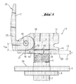
- the inventive self-locking screw 11 is a disc-shaped Tool 1 on a drive shaft 2 of a hand tool, such as attached to a grinder.
- the drive shaft 2 has a device-side stop. 3 on and is provided in the region of the free end 4 with an external thread 5.
- the self-locking screw 11 comprises a main body 12 and a pressure body 13, which is pivotally connected to the main body 12 via a connecting web 14 formed as a connecting web.
- the main body 12, the connecting web 14 formed as a connecting web and the pressure body 13 are integrally formed.
- the self-locking screw element 11 comprises a spreading element 15, which has two fork sections 16 and an actuating section 17.
- the fork sections 16 each have an eccentric pressure surface 19 due to an eccentric arrangement of the pivot axis 18 at the free ends thereof.
- the eccentric pressure surface 19 has the slightest eccentricity e min in the screw position and the greatest eccentricity emax in the clamping position.
- the main body 12 is penetrated by a thread 20, which with the external thread 5 is engageable on the drive shaft 2 in engagement.
- the pressure body 13 has an opening 21 on, which are formed in diameter larger than the outer diameter of the drive shaft 2 is.
- the operating portion 17 of the self-locking screw 11 is also provided with an opening 22 whose dimensions pivot the expansion element 15 of the fferwolf in the clamping position and from the clamping position in the Bolted position allows. In the clamping position, the expansion element 15 is substantially on the outer surface of the main body 12 at.
- the main body 12 facing side 26 of the pressure hull 13 becomes a first plane E1 and through the second surface at the, the main body 12 facing away Page 27 of the pressure hull 13, a second plane E2 is defined.
- the second Level E2 extends at an angle ⁇ of about 8 ° to the first plane E1.
Landscapes
- Engineering & Computer Science (AREA)
- General Engineering & Computer Science (AREA)
- Mechanical Engineering (AREA)
- Constituent Portions Of Griding Lathes, Driving, Sensing And Control (AREA)
- Dowels (AREA)
- Control Of Motors That Do Not Use Commutators (AREA)
Abstract
Description
- Fig. 1
- Eine Seitenansicht eines erfindungsgemässen selbstsichernden Schraubelementes in der Schraubstellung; und
- Fig. 2
- einen Längsschnitt des selbstsichernden Schraubelementes in der Spannstellung.
Claims (4)
- Selbstsicherndes Schraubelement, insbesondere zur Befestigung eines scheibenförmigen Werkzeuges (1) an einer Antriebswelle (2) eines elektromotorisch angetriebenen Handwerkzeuges, mit einem Hauptkörper (12) und einem über ein Verbindungselement (14) mit dem Hauptkörper (12) verbundenen Druckkörper (13), wobei zumindest der Hauptkörper (12) von einem Gewinde (20) durchsetzt ist und wobei der Druckkörper (13) eine erste Fläche an einer, dem Hauptkörper (12) zugewandten Seite (26) und eine zweite Fläche an einer, dem Hauptkörper (12) abgewandten Seite (27) aufweist, wobei die erste Fläche eine erste Ebene (E1) und die zweite Fläche eine zweite Ebene (E2) definiert, und das Schraubelement (11) infolge einer relativen Bewegung des Druckkörpers (13) zu dem Hauptkörper (12) mittels eines verschwenkbaren Spreizelementes (15) von einer Schraubstellung in eine Spannstellung bringbar ist, dadurch gekennzeichnet, dass die zweite Ebene (E2) zu der ersten Ebene (E1) in einem Winkel (α) verläuft.
- Schraubelement nach Anspruch 1, dadurch gekennzeichnet, dass der Winkel (α) 1° bis 15° beträgt.
- Schraubelement nach Anspruch 1 oder 2, dadurch gekennzeichnet, dass das Spreizelement (15) um eine Schwenkachse (18) am Hauptkörper (12) schwenkbar ist und eine exzentrische Druckfläche (19) aufweist, deren Radialabstand von der Schwenkachse (18) in Schwenkrichtung von der Spannstellung zur Schraubstellung hin abnimmt.
- Schraubelement nach einem der Ansprüche 1 bis 3, dadurch gekennzeichnet, dass der Hauptkörper (12), das Verbindungselement (14) und der Druckkörper (13) zusammen einteilig ausgebildet sind.
Applications Claiming Priority (2)
| Application Number | Priority Date | Filing Date | Title |
|---|---|---|---|
| DE10343753 | 2003-09-22 | ||
| DE10343753A DE10343753B4 (de) | 2003-09-22 | 2003-09-22 | Selbstsicherndes Schraubelement |
Publications (2)
| Publication Number | Publication Date |
|---|---|
| EP1517050A1 true EP1517050A1 (de) | 2005-03-23 |
| EP1517050B1 EP1517050B1 (de) | 2006-08-09 |
Family
ID=34177878
Family Applications (1)
| Application Number | Title | Priority Date | Filing Date |
|---|---|---|---|
| EP04104523A Expired - Lifetime EP1517050B1 (de) | 2003-09-22 | 2004-09-20 | Selbstsicherndes Schraubelement |
Country Status (3)
| Country | Link |
|---|---|
| EP (1) | EP1517050B1 (de) |
| AT (1) | ATE335933T1 (de) |
| DE (2) | DE10343753B4 (de) |
Cited By (10)
| Publication number | Priority date | Publication date | Assignee | Title |
|---|---|---|---|---|
| EP2213419A1 (de) * | 2009-01-30 | 2010-08-04 | C. & E. Fein GmbH | Kraftgetriebenes Handwerkzeug mit Spanneinrichtung für ein Werkzeug |
| DE102010032752A1 (de) * | 2010-07-29 | 2012-02-02 | Neumayer Tekfor Holding Gmbh | Befestigungselement |
| WO2012089638A1 (de) * | 2010-12-30 | 2012-07-05 | Robert Bosch Gmbh | Handwerkzeugmaschinenspannvorrichtung |
| JP2013040685A (ja) * | 2011-08-10 | 2013-02-28 | Newfrey Llc | 直角掛けロック・ナットを有する額縁板ブラケット |
| US20190144096A1 (en) * | 2017-11-14 | 2019-05-16 | David L. McClung | Clamping assembly |
| US20190145445A1 (en) * | 2017-11-14 | 2019-05-16 | David L. McClung | Clamping assembly |
| FR3100586A1 (fr) | 2019-09-11 | 2021-03-12 | Psa Automobiles Sa | Support de boitier électronique à levier de verrouillage |
| CN112763132A (zh) * | 2020-12-23 | 2021-05-07 | 安徽西得仪表科技有限公司 | 一种新型压力表防盗装置 |
| DE102010064372B4 (de) | 2010-12-30 | 2022-06-23 | Robert Bosch Gmbh | Handwerkzeugmaschinenspannvorrichtung |
| US11466712B2 (en) * | 2017-11-14 | 2022-10-11 | David L. McClung | Clamping assembly |
Families Citing this family (2)
| Publication number | Priority date | Publication date | Assignee | Title |
|---|---|---|---|---|
| CN106180876B (zh) * | 2016-08-31 | 2018-02-02 | 安徽安凯福田曙光车桥有限公司 | 主减速器锁紧螺母开槽压力钳 |
| TWI756523B (zh) * | 2019-03-12 | 2022-03-01 | 緯創資通股份有限公司 | 卡扣機構及電子裝置的承載結構 |
Citations (4)
| Publication number | Priority date | Publication date | Assignee | Title |
|---|---|---|---|---|
| GB280273A (en) * | 1926-08-10 | 1927-11-10 | Arthur John Wigglesworth | An improved self-locking nut for bolts, threaded screws, and the like |
| EP1125687A1 (de) * | 2000-02-16 | 2001-08-22 | DIAMANT BOART Société Anonyme | Mutter zum Spannen und Sichern eines Werkzeuges, sowie eine Scheibe auf der Spindel einer Bearbeitungsmaschine |
| US20020030328A1 (en) * | 2000-09-08 | 2002-03-14 | Stefan Nock | Clutch assembly and clamp mechanism for rotary tool disc |
| US20030147719A1 (en) * | 2001-12-12 | 2003-08-07 | Jakob Manfred | Self-locking threaded element |
Family Cites Families (2)
| Publication number | Priority date | Publication date | Assignee | Title |
|---|---|---|---|---|
| DE2228062A1 (de) * | 1972-06-09 | 1973-12-20 | Volkswagenwerk Ag | Klemmutter |
| DE4323362A1 (de) * | 1992-07-28 | 1994-02-03 | Bernhard Orlowski | Auf eine Welle aufschraubbare gegen Lösen gesicherte Spannmutter |
-
2003
- 2003-09-22 DE DE10343753A patent/DE10343753B4/de not_active Expired - Fee Related
-
2004
- 2004-09-20 EP EP04104523A patent/EP1517050B1/de not_active Expired - Lifetime
- 2004-09-20 DE DE502004001141T patent/DE502004001141D1/de not_active Expired - Lifetime
- 2004-09-20 AT AT04104523T patent/ATE335933T1/de active
Patent Citations (4)
| Publication number | Priority date | Publication date | Assignee | Title |
|---|---|---|---|---|
| GB280273A (en) * | 1926-08-10 | 1927-11-10 | Arthur John Wigglesworth | An improved self-locking nut for bolts, threaded screws, and the like |
| EP1125687A1 (de) * | 2000-02-16 | 2001-08-22 | DIAMANT BOART Société Anonyme | Mutter zum Spannen und Sichern eines Werkzeuges, sowie eine Scheibe auf der Spindel einer Bearbeitungsmaschine |
| US20020030328A1 (en) * | 2000-09-08 | 2002-03-14 | Stefan Nock | Clutch assembly and clamp mechanism for rotary tool disc |
| US20030147719A1 (en) * | 2001-12-12 | 2003-08-07 | Jakob Manfred | Self-locking threaded element |
Cited By (12)
| Publication number | Priority date | Publication date | Assignee | Title |
|---|---|---|---|---|
| EP2213419A1 (de) * | 2009-01-30 | 2010-08-04 | C. & E. Fein GmbH | Kraftgetriebenes Handwerkzeug mit Spanneinrichtung für ein Werkzeug |
| US8317574B2 (en) | 2009-01-30 | 2012-11-27 | C. & E. Fein Gmbh | Power-driven hand tool with clamping fixture for a tool |
| DE102010032752A1 (de) * | 2010-07-29 | 2012-02-02 | Neumayer Tekfor Holding Gmbh | Befestigungselement |
| WO2012089638A1 (de) * | 2010-12-30 | 2012-07-05 | Robert Bosch Gmbh | Handwerkzeugmaschinenspannvorrichtung |
| DE102010064372B4 (de) | 2010-12-30 | 2022-06-23 | Robert Bosch Gmbh | Handwerkzeugmaschinenspannvorrichtung |
| JP2013040685A (ja) * | 2011-08-10 | 2013-02-28 | Newfrey Llc | 直角掛けロック・ナットを有する額縁板ブラケット |
| US20190144096A1 (en) * | 2017-11-14 | 2019-05-16 | David L. McClung | Clamping assembly |
| US20190145445A1 (en) * | 2017-11-14 | 2019-05-16 | David L. McClung | Clamping assembly |
| US11466712B2 (en) * | 2017-11-14 | 2022-10-11 | David L. McClung | Clamping assembly |
| FR3100586A1 (fr) | 2019-09-11 | 2021-03-12 | Psa Automobiles Sa | Support de boitier électronique à levier de verrouillage |
| CN112763132A (zh) * | 2020-12-23 | 2021-05-07 | 安徽西得仪表科技有限公司 | 一种新型压力表防盗装置 |
| CN112763132B (zh) * | 2020-12-23 | 2023-12-05 | 安徽西得仪表科技有限公司 | 一种压力表防盗装置 |
Also Published As
| Publication number | Publication date |
|---|---|
| DE10343753A1 (de) | 2005-05-04 |
| EP1517050B1 (de) | 2006-08-09 |
| DE502004001141D1 (de) | 2006-09-21 |
| DE10343753B4 (de) | 2006-03-30 |
| ATE335933T1 (de) | 2006-09-15 |
Similar Documents
| Publication | Publication Date | Title |
|---|---|---|
| EP2208576B2 (de) | Oszillationsantrieb | |
| EP1531023B1 (de) | Bohrplatte welche klemmend in einem Grundkörper befestigt ist. | |
| DE102014202765B4 (de) | Befestigungskonzept zur spielfreien Montage von Verstellantrieben in einem Kraftfahrzeug | |
| EP1517050B1 (de) | Selbstsicherndes Schraubelement | |
| EP1968824B1 (de) | Scheibenwischer | |
| DE3605569A1 (de) | Schluesselloses bohrfutter sowie verfahren zur herstellung von schluessellosen bohrfuttern | |
| EP3733349A1 (de) | Spannvorrichtung für eine schraubverbindung | |
| DE3610284A1 (de) | Antriebsmechanismus mit einer gewindespindel und spindelmutter | |
| WO2007095896A1 (de) | Anlenkvorrichtung | |
| DE102012105575B4 (de) | Lagerungseinheit | |
| AT974U1 (de) | Verbindungsanordnung | |
| EP0228993B1 (de) | Vorrichtung zum Befestigen von Gegenständen an einem Untergrund | |
| EP1726403A2 (de) | Klemmhebel mit höhenverstellbarem Gegenlager | |
| DE69326168T2 (de) | Blattbefestigung für ein verstellbares schaufelblatt | |
| DE3917345A1 (de) | Einrichtung zum drehfesten vereinigen scheibenfoermiger bearbeitungswerkzeuge mit der arbeitsspindel von elektrowerkzeugen | |
| DE69615589T2 (de) | Adaption für drehende werkzeuge | |
| EP0062271B1 (de) | Befestigungselement | |
| EP1319850B1 (de) | Selbstsicherndes Schraubelement | |
| DE102005026720A1 (de) | Scheibenbremse für ein Landfahrzeug | |
| EP3523160B1 (de) | Getriebeanordnung für einen spindelantrieb, spindelantrieb und fahrzeugsitz | |
| EP2210720B1 (de) | Reibschlüssige rotationswerkzeugbefestigungsvorrichtung | |
| EP2735653B1 (de) | Formschlüssige Verbindung mit Abbruchfunktion in einer Richtung zwischen zwei Bauteilen | |
| DE8201247U1 (de) | Schaufel fuer grosse ventilatoren, geblaese und dergleichen | |
| EP0395889A2 (de) | Werkstückspannvorrichtung | |
| EP1559509B1 (de) | Vorrichtung zum Verbinden eines Schleifwerkzeugs mit einer Werkzeugmaschine |
Legal Events
| Date | Code | Title | Description |
|---|---|---|---|
| PUAI | Public reference made under article 153(3) epc to a published international application that has entered the european phase |
Free format text: ORIGINAL CODE: 0009012 |
|
| AK | Designated contracting states |
Kind code of ref document: A1 Designated state(s): AT BE BG CH CY CZ DE DK EE ES FI FR GB GR HU IE IT LI LU MC NL PL PT RO SE SI SK TR |
|
| AX | Request for extension of the european patent |
Extension state: AL HR LT LV MK |
|
| 17P | Request for examination filed |
Effective date: 20050923 |
|
| AKX | Designation fees paid |
Designated state(s): AT BE BG CH CY CZ DE DK EE ES FI FR GB GR HU IE IT LI LU MC NL PL PT RO SE SI SK TR |
|
| GRAP | Despatch of communication of intention to grant a patent |
Free format text: ORIGINAL CODE: EPIDOSNIGR1 |
|
| GRAS | Grant fee paid |
Free format text: ORIGINAL CODE: EPIDOSNIGR3 |
|
| GRAA | (expected) grant |
Free format text: ORIGINAL CODE: 0009210 |
|
| AK | Designated contracting states |
Kind code of ref document: B1 Designated state(s): AT BE BG CH CY CZ DE DK EE ES FI FR GB GR HU IE IT LI LU MC NL PL PT RO SE SI SK TR |
|
| PG25 | Lapsed in a contracting state [announced via postgrant information from national office to epo] |
Ref country code: PL Free format text: LAPSE BECAUSE OF FAILURE TO SUBMIT A TRANSLATION OF THE DESCRIPTION OR TO PAY THE FEE WITHIN THE PRESCRIBED TIME-LIMIT Effective date: 20060809 Ref country code: SK Free format text: LAPSE BECAUSE OF FAILURE TO SUBMIT A TRANSLATION OF THE DESCRIPTION OR TO PAY THE FEE WITHIN THE PRESCRIBED TIME-LIMIT Effective date: 20060809 Ref country code: CZ Free format text: LAPSE BECAUSE OF FAILURE TO SUBMIT A TRANSLATION OF THE DESCRIPTION OR TO PAY THE FEE WITHIN THE PRESCRIBED TIME-LIMIT Effective date: 20060809 Ref country code: RO Free format text: LAPSE BECAUSE OF FAILURE TO SUBMIT A TRANSLATION OF THE DESCRIPTION OR TO PAY THE FEE WITHIN THE PRESCRIBED TIME-LIMIT Effective date: 20060809 Ref country code: IE Free format text: LAPSE BECAUSE OF FAILURE TO SUBMIT A TRANSLATION OF THE DESCRIPTION OR TO PAY THE FEE WITHIN THE PRESCRIBED TIME-LIMIT Effective date: 20060809 Ref country code: SI Free format text: LAPSE BECAUSE OF FAILURE TO SUBMIT A TRANSLATION OF THE DESCRIPTION OR TO PAY THE FEE WITHIN THE PRESCRIBED TIME-LIMIT Effective date: 20060809 |
|
| REG | Reference to a national code |
Ref country code: GB Ref legal event code: FG4D Free format text: NOT ENGLISH |
|
| REG | Reference to a national code |
Ref country code: CH Ref legal event code: EP |
|
| REG | Reference to a national code |
Ref country code: IE Ref legal event code: FG4D Free format text: LANGUAGE OF EP DOCUMENT: GERMAN |
|
| REF | Corresponds to: |
Ref document number: 502004001141 Country of ref document: DE Date of ref document: 20060921 Kind code of ref document: P |
|
| PG25 | Lapsed in a contracting state [announced via postgrant information from national office to epo] |
Ref country code: MC Free format text: LAPSE BECAUSE OF NON-PAYMENT OF DUE FEES Effective date: 20060930 |
|
| GBT | Gb: translation of ep patent filed (gb section 77(6)(a)/1977) |
Effective date: 20060923 |
|
| PG25 | Lapsed in a contracting state [announced via postgrant information from national office to epo] |
Ref country code: BG Free format text: LAPSE BECAUSE OF FAILURE TO SUBMIT A TRANSLATION OF THE DESCRIPTION OR TO PAY THE FEE WITHIN THE PRESCRIBED TIME-LIMIT Effective date: 20061109 Ref country code: DK Free format text: LAPSE BECAUSE OF FAILURE TO SUBMIT A TRANSLATION OF THE DESCRIPTION OR TO PAY THE FEE WITHIN THE PRESCRIBED TIME-LIMIT Effective date: 20061109 |
|
| PG25 | Lapsed in a contracting state [announced via postgrant information from national office to epo] |
Ref country code: ES Free format text: LAPSE BECAUSE OF FAILURE TO SUBMIT A TRANSLATION OF THE DESCRIPTION OR TO PAY THE FEE WITHIN THE PRESCRIBED TIME-LIMIT Effective date: 20061120 |
|
| REG | Reference to a national code |
Ref country code: SE Ref legal event code: TRGR |
|
| PG25 | Lapsed in a contracting state [announced via postgrant information from national office to epo] |
Ref country code: PT Free format text: LAPSE BECAUSE OF FAILURE TO SUBMIT A TRANSLATION OF THE DESCRIPTION OR TO PAY THE FEE WITHIN THE PRESCRIBED TIME-LIMIT Effective date: 20070109 |
|
| ET | Fr: translation filed | ||
| REG | Reference to a national code |
Ref country code: IE Ref legal event code: FD4D |
|
| PLBE | No opposition filed within time limit |
Free format text: ORIGINAL CODE: 0009261 |
|
| STAA | Information on the status of an ep patent application or granted ep patent |
Free format text: STATUS: NO OPPOSITION FILED WITHIN TIME LIMIT |
|
| 26N | No opposition filed |
Effective date: 20070510 |
|
| PG25 | Lapsed in a contracting state [announced via postgrant information from national office to epo] |
Ref country code: GR Free format text: LAPSE BECAUSE OF FAILURE TO SUBMIT A TRANSLATION OF THE DESCRIPTION OR TO PAY THE FEE WITHIN THE PRESCRIBED TIME-LIMIT Effective date: 20061110 |
|
| PG25 | Lapsed in a contracting state [announced via postgrant information from national office to epo] |
Ref country code: EE Free format text: LAPSE BECAUSE OF FAILURE TO SUBMIT A TRANSLATION OF THE DESCRIPTION OR TO PAY THE FEE WITHIN THE PRESCRIBED TIME-LIMIT Effective date: 20060809 |
|
| PG25 | Lapsed in a contracting state [announced via postgrant information from national office to epo] |
Ref country code: LU Free format text: LAPSE BECAUSE OF NON-PAYMENT OF DUE FEES Effective date: 20060920 Ref country code: TR Free format text: LAPSE BECAUSE OF FAILURE TO SUBMIT A TRANSLATION OF THE DESCRIPTION OR TO PAY THE FEE WITHIN THE PRESCRIBED TIME-LIMIT Effective date: 20060809 Ref country code: HU Free format text: LAPSE BECAUSE OF FAILURE TO SUBMIT A TRANSLATION OF THE DESCRIPTION OR TO PAY THE FEE WITHIN THE PRESCRIBED TIME-LIMIT Effective date: 20070210 |
|
| PG25 | Lapsed in a contracting state [announced via postgrant information from national office to epo] |
Ref country code: CY Free format text: LAPSE BECAUSE OF FAILURE TO SUBMIT A TRANSLATION OF THE DESCRIPTION OR TO PAY THE FEE WITHIN THE PRESCRIBED TIME-LIMIT Effective date: 20060809 |
|
| REG | Reference to a national code |
Ref country code: FR Ref legal event code: PLFP Year of fee payment: 13 |
|
| REG | Reference to a national code |
Ref country code: FR Ref legal event code: PLFP Year of fee payment: 14 |
|
| REG | Reference to a national code |
Ref country code: FR Ref legal event code: PLFP Year of fee payment: 15 |
|
| PGFP | Annual fee paid to national office [announced via postgrant information from national office to epo] |
Ref country code: DE Payment date: 20180920 Year of fee payment: 15 Ref country code: IT Payment date: 20180925 Year of fee payment: 15 Ref country code: FR Payment date: 20180924 Year of fee payment: 15 |
|
| PGFP | Annual fee paid to national office [announced via postgrant information from national office to epo] |
Ref country code: SE Payment date: 20180919 Year of fee payment: 15 Ref country code: BE Payment date: 20180919 Year of fee payment: 15 Ref country code: FI Payment date: 20180920 Year of fee payment: 15 Ref country code: NL Payment date: 20180919 Year of fee payment: 15 Ref country code: CH Payment date: 20180919 Year of fee payment: 15 Ref country code: GB Payment date: 20180919 Year of fee payment: 15 Ref country code: AT Payment date: 20180920 Year of fee payment: 15 |
|
| REG | Reference to a national code |
Ref country code: DE Ref legal event code: R119 Ref document number: 502004001141 Country of ref document: DE |
|
| REG | Reference to a national code |
Ref country code: FI Ref legal event code: MAE |
|
| PG25 | Lapsed in a contracting state [announced via postgrant information from national office to epo] |
Ref country code: SE Free format text: LAPSE BECAUSE OF NON-PAYMENT OF DUE FEES Effective date: 20190921 Ref country code: FI Free format text: LAPSE BECAUSE OF NON-PAYMENT OF DUE FEES Effective date: 20190920 |
|
| REG | Reference to a national code |
Ref country code: SE Ref legal event code: EUG |
|
| REG | Reference to a national code |
Ref country code: NL Ref legal event code: MM Effective date: 20191001 |
|
| REG | Reference to a national code |
Ref country code: CH Ref legal event code: PL |
|
| PG25 | Lapsed in a contracting state [announced via postgrant information from national office to epo] |
Ref country code: CH Free format text: LAPSE BECAUSE OF NON-PAYMENT OF DUE FEES Effective date: 20190930 Ref country code: LI Free format text: LAPSE BECAUSE OF NON-PAYMENT OF DUE FEES Effective date: 20190930 Ref country code: NL Free format text: LAPSE BECAUSE OF NON-PAYMENT OF DUE FEES Effective date: 20191001 Ref country code: DE Free format text: LAPSE BECAUSE OF NON-PAYMENT OF DUE FEES Effective date: 20200401 |
|
| REG | Reference to a national code |
Ref country code: BE Ref legal event code: MM Effective date: 20190930 |
|
| REG | Reference to a national code |
Ref country code: AT Ref legal event code: MM01 Ref document number: 335933 Country of ref document: AT Kind code of ref document: T Effective date: 20190920 |
|
| PG25 | Lapsed in a contracting state [announced via postgrant information from national office to epo] |
Ref country code: BE Free format text: LAPSE BECAUSE OF NON-PAYMENT OF DUE FEES Effective date: 20190930 Ref country code: IT Free format text: LAPSE BECAUSE OF NON-PAYMENT OF DUE FEES Effective date: 20190920 |
|
| GBPC | Gb: european patent ceased through non-payment of renewal fee |
Effective date: 20190920 |
|
| PG25 | Lapsed in a contracting state [announced via postgrant information from national office to epo] |
Ref country code: FR Free format text: LAPSE BECAUSE OF NON-PAYMENT OF DUE FEES Effective date: 20190930 Ref country code: GB Free format text: LAPSE BECAUSE OF NON-PAYMENT OF DUE FEES Effective date: 20190920 |
|
| PG25 | Lapsed in a contracting state [announced via postgrant information from national office to epo] |
Ref country code: AT Free format text: LAPSE BECAUSE OF NON-PAYMENT OF DUE FEES Effective date: 20190920 |