EP1516992A2 - Dorsill structure for out-swinging type door - Google Patents
Dorsill structure for out-swinging type door Download PDFInfo
- Publication number
- EP1516992A2 EP1516992A2 EP04021669A EP04021669A EP1516992A2 EP 1516992 A2 EP1516992 A2 EP 1516992A2 EP 04021669 A EP04021669 A EP 04021669A EP 04021669 A EP04021669 A EP 04021669A EP 1516992 A2 EP1516992 A2 EP 1516992A2
- Authority
- EP
- European Patent Office
- Prior art keywords
- plate
- doorsill
- seat
- rain shielding
- slot
- Prior art date
- Legal status (The legal status is an assumption and is not a legal conclusion. Google has not performed a legal analysis and makes no representation as to the accuracy of the status listed.)
- Withdrawn
Links
Images


Classifications
-
- E—FIXED CONSTRUCTIONS
- E06—DOORS, WINDOWS, SHUTTERS, OR ROLLER BLINDS IN GENERAL; LADDERS
- E06B—FIXED OR MOVABLE CLOSURES FOR OPENINGS IN BUILDINGS, VEHICLES, FENCES OR LIKE ENCLOSURES IN GENERAL, e.g. DOORS, WINDOWS, BLINDS, GATES
- E06B1/00—Border constructions of openings in walls, floors, or ceilings; Frames to be rigidly mounted in such openings
- E06B1/70—Sills; Thresholds
Definitions
- the invention relates to a doorsill structure, particularly a doorsill structure for out-swinging type door having the effect of shielding the winds and keeping off the water to prevent the water from seeping into the room.
- the major purpose of the invention is disclosed a doorsill structure for out-swinging type door having excellent waterproof effect formed by snap-in assembling of a doorsill seat and a rain shielding plate without using any fastening part.
- a doorsill structure for out-swinging type door can be equipped with a soft packing strip through which a tight contact between door surface of a hinged door and doorsill can be achieved, and provides the excellent effect of shielding the winds and preventing the water from seeping into the room.
- the present invention has invented two preferred embodiments of doorsill structure for out-swinging type door particularly under stress of harsh weather having the effect of shielding the winds and keeping off the water to prevent the water from seeping into the room.
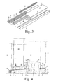
- the first embodiment of doorsill (10) of the invention is depicted as Figure 1 through 4 which comprises a doorsill seat (20), a rain shielding plate (30) and a side plate (40), or even further comprising a soft packing strip (50), and all components are assembled together by using snap-in connecting method without any fastening part.
- the doorsill seat (20) is made of thermoplastic foam material or thermoplastic material by extruding forming technique to form an integral structure. As shown in Figure 2, the doorsill seat (20) has a protruding ridge (21), a front-plate (22) and a back-plate (23) wherein the front-plate (22) and the back-plate (23) are respectively joined to and extended from the front and back side of the protruding ridge (21).
- a slot shaped recession (26) and a snapping slot (27) are respectively formed along the longitudinal direction of the protruding ridge (21), and on the other vertical portion of the protruding ridge (21) where joining to the back-plate (23) a tenon-slot (28) for tenon connection purpose is formed at the junction position of the protruding ridge (21) and the back-plate (23) of the doorsill seat (20).
- the front-plate (22) of the doorsill seat (20) is a plate inclined down to its front side having part of the thickness of the bottom side of its end portion cut away, or reduced, and has a slot (24) for snap-in connection purpose formed on the bottom side at the position adjoining to the portion where the thickness is reduced, so that a wedge shaped rib (25) is formed in the slot (24) to enable the front part of the front-plate (22) to be used as a means for connecting other part by snap-in method.
- a part of the thickness is cut away, and a tenon-slot (29) for tenon connection purpose is formed in proper position to enable the front part of the back-plate (23) to be connected with another part by way of snap-in.
- the rain shielding plate (30) is made of aluminum alloy or thermoplastic material by extruding forming technique, and comprises a cover plate (31), a connecting plate (32) and a baffle plate (33) to provide the effect of moisture-proof and waterproof.
- the cover plate (31) of the rain shielding plate (30) is an inclined plate with inclination angle same as that of the front plate (22) of the aforesaid doorsill seat (20).
- the cover plate (31) has a reverse hook-rib (34) formed at the end position in greater height for the purpose of snap-in connection.
- the connecting plate (32) of the rain shielding plate (30) is a L-shaped plate which has a vertical portion joined to the bottom surface of the front section of the cover plate (31), and a horizontal portion with a small part of its end bended upwardly to form a reverse hook-rib (35) for snap-in connecting purpose.
- the space in between the cover plate (31) and the connecting plate (32) is for accommodating the front part of the front-plate (22) of the doorsill seat (20), and in the meantime the reverse hook-rib (35) of the connecting plate (32) shall snap with the wedge shaped rib (25) of the front-plate (22) to form a snap-in assembled structure.
- the baffle plate (33) of the rain shielding plate (30) is provided with a vertical portion joined to the upper surface of the cover plate (31), and a horizontal portion extended from the top end of the vertical portion.
- the out-swinging hinged door (60) will touch and press the soft packing strip (50) installed on the doorsill (10) of the invention to achieve a tight contact with the soft packing strip (50) when the out-swinging hinged door (60) is closed.
- the side plate (40) is used for mounting a screen door (not shown in the drawings), and has a horizontal plate (41) and a reversed L-shaped plate (42) with its vertical part joined to the horizontal plate (41). Therefore, on the surface of the horizontal plate (41) of the side plate (40) a sliding rail (43) is formed upwardly for mounting a screen door (not shown in the drawings) which can slide on the sliding rail (43).
- the horizontal plate (41) of the side plate (40) has a hook-rib (44) formed at its front end and the reversed L-shaped plate (42) of the side plate (40) also has a reverse hook-rib (45) formed at front end of its horizontal portion.
- the first embodiment of doorsill (10) of the invention can be easily and rapidly constructed by assembling these parts together.
- the second embodiment of doorsill (10) of the invention is depicted as in Figure 5 through 8 which is without a side plate (40) and which comprises a doorsill seat (20') and a rain shielding plate (30'), or even further comprising a soft packing strip (50), and the three components of the doorsill seat (20'), the rain shielding plate (30') and the soft packing strip (50) are assembled together by using snap-in connecting method without any fastening part.
- the detailed structure of the doorsill seat (20') of the second embodiment of doorsill (10), due to almost same as that of the doorsill base (20) of the first embodiment of doorsill (10) of the invention, may refer to and understand from the aforesaid description to that of doorsill seat (20) of the first embodiment of doorsill (10) of the invention.
- the rain shielding plate (30') is made of aluminum alloy or thermoplastic material by extruding forming technique, and comprises a cover plate (31), a connecting plate (32) and a holding plate (33) to provide the effect of moisture-proof and waterproof.
- the function and detailed structure of the cover plate (31) and the connecting plate (32) of the rain shielding plate (30') of the second embodiment of doorsill (10), due to same as that of the rain shielding plate (30) of the first embodiment of doorsill (10) of the invention, may refer to and understand from the aforesaid description to that of the cover plate (31) and the connecting plate (32) of the rain shielding plate (30) of the first embodiment of doorsill (10) of the invention.
- the holding plate (36) of the rain shielding plate (30') is provided with a vertical portion joined to the upper surface of the cover plate (31), and a bending portion (37) with an inserted slot (38) formed on the vertical portion of the holding plate (36).
- the bending portion (37) of the holding plate (36) is inserted and installed into the slot shaped recession (26) of the doorsill seat (20').
- a soft packing strip (50) with a griping-mounting piece (51) shall be installed onto the holding plate (36) of the rain shielding plate (30') by way of having its griping-mounting piece (51) wholly inserted into the inserted slot (38) of the holding plate (36), and the soft packing strip (50) is then positioned on the outer side of the holding plate (36).
- the out-swinging hinged door (60) will touch and press the soft packing strip (50) installed on the doorsill (10) of the invention to achieve a tight contact with the soft packing strip (50) when the out-swinging hinged door (60) is closed.
- the second embodiment of the doorsill (10) of the invention may be easily and rapidly constructed by assembling these parts together.
- the first or second embodiment of doorsill (10) of the invention may be assembled with two jamb (15) installed on both sides of the doorsill (10) and a transom (not shown in the drawings) installed above and parallel to the doorsill (10) to form a doorframe assembly for installing an out-swinging hinged door (60), and by this way to separate the interior (70) and exterior (80). Therefore, the manner to open the out-swinging hinged door (60) is to push the out-swinging hinged door (60) from the interior (70) to the exterior (80), or to pull the out-swinging hinged door (60) from the exterior (80).
- the rain shielding plate (30) or (30') of the doorsill (10) is made of aluminum alloy and possesses the effect of moisture-proof and waterproof. Besides, since the doorsill (10) itself is also higher than the bottom edge of the out-swinging hinged door (60), the doorsill (10) of the invention will form a wall for keeping off the water from the interior (70).
- the out-swinging hinged door (60) when the out-swinging hinged door (60) is closed, the out-swinging hinged door (60) shall tough and press the soft packing strip (50) on the doorsill (10) to form a tight contact to seal up the gap which might exist between the bottom edge of the door (60) and the floor surface of the interior (70) to achieve a dual protecting structure, so that the first or second embodiment of doorsill (10) of the invention shall provide the effect of preventing the water from seeping into the interior (70) under stress of weather..
Landscapes
- Engineering & Computer Science (AREA)
- Civil Engineering (AREA)
- Structural Engineering (AREA)
- Specific Sealing Or Ventilating Devices For Doors And Windows (AREA)
- Building Environments (AREA)
Abstract
Description
Claims (10)
- A doorsill structure for out-swinging type door formed by snap-in connecting a doorsill seat, and a rain shielding plate wherein
the doorsill seat is formed by a longitudinal protruding ridge, a front-plate joined to the bottom section on one side of the protruding ridge and a back-plate joined to the bottom section on the other side of the protruding ridge; and the front-plate is an inclined plate which bottom side of its front end is reduced thickness where a slot is formed; and
the rain shielding plate comprises at least a cover plate and a connecting plate, wherein the cover plate is a inclined plate with the inclination angle same as that of the front plate of the doorsill base, and the connecting plate is a L-shaped plate with its vertical portion joined to the cover plate and the end of its horizontal portion has a reverse hook-rib formed upwardly. - The doorsill structure as defined in claim 1, further comprising a side plate by snap-in connection joined to the back-plate of the doorsill seat, and the side plate has a horizontal plate on which surface has a sliding rail.
- The doorsill structure as defined in claim 1 or claim 2, wherein the doorsill seat has a slot shaped recession formed on the vertical portion of the protruding ridge where joining to the front-plate.
- The doorsill structure as defined in claim 3, wherein the rain shielding plate further comprises a baffle plate which has a vertical portion joined to the cover plate and a horizontal portion extended from the top end of the vertical portion, and the baffle plate is positioned into the slot shaped recession of the doorsill seat to form an inserted slot provided for installing a soft packing strip.
- The doorsill structure as defined in claim 4, further comprising a soft packing strip with a griping-mounting piece inserted into the inserted slot.
- The doorsill structure as defined in claim 3, wherein the rain shielding plate further comprises a holding plate which has a vertical portion joined to the cover plate and a bending portion with an inserted slot, and the holding plate is positioned into the slot shaped recession of the doorsill seat.
- The doorsill structure as defined in claim 6, further comprising a soft packing strip with a griping-mounting piece inserted into the inserted slot of the holding plate of the rain shielding plate.
- The doorsill structure as defined in any of claim 1 to 7, wherein the doorsill seat has a snapping slot formed at the junction of the protruding ridge and the front-plate, and the cover plate of the rain shielding plate has a reverse hook-rib formed upwardly at the higher end.
- The doorsill structure as defined in any of claim 1 to 7, wherein the doorsill seat is formed by thermoplastic foam material or thermoplastic material.
- The doorsill structure as defined in any of claim 1 to 7, wherein the rain shielding plate is made of aluminum alloy or thermoplastic material.
Applications Claiming Priority (2)
| Application Number | Priority Date | Filing Date | Title |
|---|---|---|---|
| CN03279795 | 2003-09-19 | ||
| CNU032797958U CN2672244Y (en) | 2003-09-19 | 2003-09-19 | Threshold structure of out ward push door leaf |
Publications (2)
| Publication Number | Publication Date |
|---|---|
| EP1516992A2 true EP1516992A2 (en) | 2005-03-23 |
| EP1516992A3 EP1516992A3 (en) | 2006-05-31 |
Family
ID=34169875
Family Applications (1)
| Application Number | Title | Priority Date | Filing Date |
|---|---|---|---|
| EP04021669A Withdrawn EP1516992A3 (en) | 2003-09-19 | 2004-09-13 | Dorsill structure for out-swinging type door |
Country Status (2)
| Country | Link |
|---|---|
| EP (1) | EP1516992A3 (en) |
| CN (1) | CN2672244Y (en) |
Cited By (5)
| Publication number | Priority date | Publication date | Assignee | Title |
|---|---|---|---|---|
| DE102008015725A1 (en) | 2008-03-26 | 2009-10-08 | Weru Ag | Door-or window arrangement, has auxiliary profile forming outwardly aligned weather board arranged at lower cross bar of leaf, and fitting retention groove formed in auxiliary profile made of plastic |
| WO2013072911A1 (en) * | 2011-11-14 | 2013-05-23 | J. I. Peled Ltd | Clad slat |
| CN108412368A (en) * | 2018-03-19 | 2018-08-17 | 杭州富阳富腾人防设备有限公司 | A kind of movable sill formula closed guard gate |
| EP3748115A1 (en) * | 2019-06-04 | 2020-12-09 | HAUTAU GmbH | Threshold for a sliding door |
| CN113942408A (en) * | 2020-07-15 | 2022-01-18 | 许继电气股份有限公司 | L-shaped charging pile |
Families Citing this family (6)
| Publication number | Priority date | Publication date | Assignee | Title |
|---|---|---|---|---|
| CN101709618B (en) * | 2009-11-06 | 2011-11-16 | 浙江瑞明节能门窗有限公司 | Novel door sill of vertical hinged door |
| CN103452432B (en) * | 2012-05-30 | 2016-09-14 | 沈阳远大铝业工程有限公司 | The accessible vertical hinged door of high watertightness, air-tightness |
| CN104295186A (en) * | 2014-10-16 | 2015-01-21 | 国家电网公司 | Transformer substation outdoor windowsill drainage structure |
| CN104632008B (en) * | 2015-02-16 | 2016-06-22 | 浙江宏博新型建材有限公司 | A kind of Comecting structure with ramps of threshold system |
| CN104632009B (en) * | 2015-02-16 | 2016-04-06 | 浙江宏博新型建材有限公司 | A kind of threshold system |
| CN108086489B (en) * | 2016-11-22 | 2020-07-31 | 得意昭和防水工程行 | Water-stop structure with adjustable-height water-stop pier and its application method |
Family Cites Families (5)
| Publication number | Priority date | Publication date | Assignee | Title |
|---|---|---|---|---|
| US4207707A (en) * | 1978-07-17 | 1980-06-17 | Lancer Corporation | Metal cladded window products |
| US4716683A (en) * | 1985-05-13 | 1988-01-05 | Rolscreen Company | Door weatherstripping assembly |
| US5553419A (en) * | 1994-06-30 | 1996-09-10 | Renaissance French Doors & Sash, Inc. | Door threshold assembly |
| US6125605A (en) * | 1998-04-03 | 2000-10-03 | Young; Robert H. | Cladding for trim members used on buildings |
| FR2832754B1 (en) * | 2001-11-29 | 2004-09-24 | Rehau Sa | THERMAL BRIDGE BREAK THRESHOLD FOR WINDOW HOLDER AND THE LIKE |
-
2003
- 2003-09-19 CN CNU032797958U patent/CN2672244Y/en not_active Expired - Lifetime
-
2004
- 2004-09-13 EP EP04021669A patent/EP1516992A3/en not_active Withdrawn
Cited By (7)
| Publication number | Priority date | Publication date | Assignee | Title |
|---|---|---|---|---|
| DE102008015725A1 (en) | 2008-03-26 | 2009-10-08 | Weru Ag | Door-or window arrangement, has auxiliary profile forming outwardly aligned weather board arranged at lower cross bar of leaf, and fitting retention groove formed in auxiliary profile made of plastic |
| WO2013072911A1 (en) * | 2011-11-14 | 2013-05-23 | J. I. Peled Ltd | Clad slat |
| CN108412368A (en) * | 2018-03-19 | 2018-08-17 | 杭州富阳富腾人防设备有限公司 | A kind of movable sill formula closed guard gate |
| EP3748115A1 (en) * | 2019-06-04 | 2020-12-09 | HAUTAU GmbH | Threshold for a sliding door |
| DE102019114933A1 (en) * | 2019-06-04 | 2020-12-10 | Hautau Gmbh | Threshold for a sliding door |
| CN113942408A (en) * | 2020-07-15 | 2022-01-18 | 许继电气股份有限公司 | L-shaped charging pile |
| CN113942408B (en) * | 2020-07-15 | 2024-03-08 | 许继电气股份有限公司 | An L-shaped charging pile |
Also Published As
| Publication number | Publication date |
|---|---|
| EP1516992A3 (en) | 2006-05-31 |
| CN2672244Y (en) | 2005-01-19 |
Similar Documents
| Publication | Publication Date | Title |
|---|---|---|
| US6789359B2 (en) | Weeped end plug for sill assembly | |
| US6334283B1 (en) | Water resistant window frame | |
| US4237664A (en) | Sliding door unit | |
| US7266929B1 (en) | Threshold and detachable sealing fin | |
| US4768316A (en) | Casement windows | |
| EP1186740B1 (en) | Adjustable door frame assembly | |
| US4665654A (en) | Weather-tight switchboard cabinet | |
| EP1516992A2 (en) | Dorsill structure for out-swinging type door | |
| CA2881561C (en) | Door jamb and sill assemblies | |
| US20110139379A1 (en) | Door assembly | |
| US4996814A (en) | Insulated, weatherproof window frame of synthetic resin material | |
| CA2615322A1 (en) | Z-bar extension member and assembly | |
| EP1870532A2 (en) | Rooflight | |
| EP1533436B1 (en) | Covering sealing element for roof window | |
| CN204152099U (en) | With the femerell of window frame cladding system | |
| JP2000145304A (en) | Composite sash | |
| EP1516991A2 (en) | Doorsill structure for in-swinging type door | |
| JP3378170B2 (en) | Insulation shoji | |
| JPH094328A (en) | Heat insulating sash | |
| JP3179727B2 (en) | Composite sash | |
| JP3100755U (en) | Door sill structure | |
| JP3137602B2 (en) | Window sash | |
| JPH041267Y2 (en) | ||
| JP6816966B2 (en) | A shutter case equipped with an eave and a shutter device equipped with the shutter case. | |
| JP3964376B2 (en) | Sash window |
Legal Events
| Date | Code | Title | Description |
|---|---|---|---|
| PUAI | Public reference made under article 153(3) epc to a published international application that has entered the european phase |
Free format text: ORIGINAL CODE: 0009012 |
|
| AK | Designated contracting states |
Kind code of ref document: A2 Designated state(s): AT BE BG CH CY CZ DE DK EE ES FI FR GB GR HU IE IT LI LU MC NL PL PT RO SE SI SK TR |
|
| AX | Request for extension of the european patent |
Extension state: AL HR LT LV MK |
|
| PUAL | Search report despatched |
Free format text: ORIGINAL CODE: 0009013 |
|
| AK | Designated contracting states |
Kind code of ref document: A3 Designated state(s): AT BE BG CH CY CZ DE DK EE ES FI FR GB GR HU IE IT LI LU MC NL PL PT RO SE SI SK TR |
|
| AX | Request for extension of the european patent |
Extension state: AL HR LT LV MK |
|
| 17P | Request for examination filed |
Effective date: 20061130 |
|
| AKX | Designation fees paid |
Designated state(s): DE ES FR GB IT NL |
|
| STAA | Information on the status of an ep patent application or granted ep patent |
Free format text: STATUS: THE APPLICATION IS DEEMED TO BE WITHDRAWN |
|
| 18D | Application deemed to be withdrawn |
Effective date: 20090401 |