EP1516802B1 - Side wall pillar of a bus - Google Patents
Side wall pillar of a bus Download PDFInfo
- Publication number
- EP1516802B1 EP1516802B1 EP04021407A EP04021407A EP1516802B1 EP 1516802 B1 EP1516802 B1 EP 1516802B1 EP 04021407 A EP04021407 A EP 04021407A EP 04021407 A EP04021407 A EP 04021407A EP 1516802 B1 EP1516802 B1 EP 1516802B1
- Authority
- EP
- European Patent Office
- Prior art keywords
- hollow profile
- section
- supporting column
- column according
- column
- Prior art date
- Legal status (The legal status is an assumption and is not a legal conclusion. Google has not performed a legal analysis and makes no representation as to the accuracy of the status listed.)
- Expired - Lifetime
Links
Images

Classifications
-
- B—PERFORMING OPERATIONS; TRANSPORTING
- B62—LAND VEHICLES FOR TRAVELLING OTHERWISE THAN ON RAILS
- B62D—MOTOR VEHICLES; TRAILERS
- B62D31/00—Superstructures for passenger vehicles
- B62D31/02—Superstructures for passenger vehicles for carrying large numbers of passengers, e.g. omnibus
Definitions
- the invention relates to a side wall pillar of a bus, which is connectable at opposite ends, each with a frame member and having a closed, extending between the two ends hollow profile element.
- Bodywork skeleton which are constructed from a variety of sidewall columns and longitudinal, transverse, floor and roof racks, are well known in the automotive industry and are mainly used in bus construction in many cases.
- An essential component of a body frame is the side wall pillar, which is intended both for supporting the roof and floor elements as well as for fastening windows and sheet metal. So that the sheet metal panels in the upper part of a Omnisbusses and the surface of the trunk flaps form a flat surface, the sidewall column is split. While the upper part of the sidewall pillar in the body rib represents the connection between the roof beams and the longitudinal profile, the lower part of the sidewall pillar is slightly offset rearwardly from the longitudinal profile to the floor beams.
- a console is provided in the region of the node formed from the upper and lower side wall pillar and the longitudinal profile, which serves as a support for the floor.
- the unit of sidewall columns, roof and floor or floor elements supporting cross members form a so-called annular frame, which can be exposed to vibration loads and bending stresses during the ride, especially in an accident.
- annular frame which can be exposed to vibration loads and bending stresses during the ride, especially in an accident.
- bodywork ribs for example, also provided at the junction sidewall pillar / longitudinal profile / floor support special fittings that strengthen the side wall locally or attached in the form of angle elements between adjacent support.
- Such a node reinforcement for skeleton structures of commercial vehicles is, for example, from the DE 199 29 219 A1 known.
- reinforcements are welded to the side walls of the mutually perpendicular frame support at the openings of a skeleton, for example.
- This additional connection of adjacent frame girders enhances the rigidity of the girder structure.
- the attachment takes place here by Anyaken or welding.
- a disadvantage of the system described is that a significant number of node reinforcements is needed and beyond the production of the required welds is very time consuming.
- the invention is therefore based on the object to provide a support column for a bodywork skeleton of a motor vehicle, which meets the safety requirements, in particular with respect to the required inside the passenger compartment survival space, and at the same time cost and with relatively low manufacturing expense is to produce.
- the support column should be designed to save space, so that the space available for use is not limited.
- the invention relates to a side wall pillar of a bus, which is connectable at opposite ends with at least one body element and which has a hollow profile element (2) extending between the two ends, which is made in one piece and has a longitudinal center axis which is curved or at least not two having parallel portions, wherein at the opposite ends outer pillar portions connect, between which a central pillar portion is provided, and which is characterized in that the longitudinal center axis in the region of the central pillar portion connecting the two outer pillar portions is curved, or at least two not has parallel sections and the central column section in at least one direction of stress has a greater moment of resistance to bending than the outer column sections, wherein in the region of the central column section least s a reinforcing element is provided, which has at least partially a contact area with the hollow profile element and which is disposed within the hollow profile element.
- the effective cross section of the column in this area is increased and / or the material properties are correspondingly improved. This is done either by the provision of an additional reinforcing element, the sectional use of a material of higher quality and / or the selection of a relation to the outer column sections greater wall thickness of the hollow profile element in the central column section.
- a material of higher quality in the middle column section it is of course also conceivable to compensate for the material provided for the hollow profile element in this area in such a way that it has improved material properties.
- a support column for a bodywork skeleton of a motor vehicle is realized, which can be used due to the special shape in areas in which the space is cramped.
- the one-piece design of the hollow profile element and the reinforcement of the support column in the central column area ensure easy manufacture and assembly or attachment of the column in a body skeleton, without sacrificing strength and rigidity.
- a carrier element is provided with the support column according to the invention, which also at connection nodes, for example.
- On a longitudinal member of a bus Karosseriegerippes does not have to be shared, but due to its shape is integrally fed past the carrier.
- the solution according to the invention allows the flexible use of high-strength support columns at various points of a body frame, taking into account special design requirements.
- the extending between the ends of the support column in the longitudinal direction hollow profile element is made in one piece.
- the hollow profile element is either a component or that the hollow profile element has been assembled to a one-piece component before installation in a body skeleton of a plurality of components, for example.
- the support column is at the moment of installation in a body frame as a component available, so that the corresponding column can be easily inserted into the skeleton and connected to the corresponding body elements.
- the support column is to be connected at opposite ends with body elements, such as a floor and a roof rack. However, this does not exclude that the support column is connected to other body elements. So it is conceivable, for example, that in the central column area brackets are attached as brackets of a false floor or that at least in sections, a planking is attached to the support column.
- the support column can theoretically be subdivided into three sections, of which the outer column sections preferably each lie at least partially in planes arranged parallel to one another.
- the central column section is formed in such a column so that this section constitutes the connecting element between the two outer column sections.
- the central pillar portion has two ends, which are respectively connected to the outer pillar portions and thus at least contact a plane in which the outer pillar portions, or at least the middle pillar portion facing end portions of the outer pillar portions are arranged.
- the hollow profile element of the support column according to the invention preferably has an at least approximately rectangular, in particular 60 ⁇ 40 mm 2, large cross section. But it is also conceivable that the cross section has another polygonal or even round contour.
- a further particular embodiment provides a hollow profile element with a square cross section with preferred dimensions of 40 ⁇ 40, 50 ⁇ 50 or 80 ⁇ 80 mm 2 .
- the material is the use of a high-strength steel with a minimum yield strength of 420 N / mm 2 , preferably from
- the hollow profile element in the region of the central column section at least partially has a greater wall thickness than in the region of the outer column sections.
- the wall thickness of the hollow profile is reinforced in this case such that the middle column section of the support column according to the invention has a greater resistance to bending than the outer column sections in at least one possible stress direction.
- at least one additional reinforcing element in the central column section which is arranged outside, for example as a sleeve, or within the hollow profile such that at least in sections a contact surface between the hollow profile and reinforcing element is formed.
- the reinforcing element is connected by means of plug welds with the hollow profile element.
- the reinforcing element is arranged in the central column section within the hollow profile element and a hollow profile, in particular with a rectangular or even square cross-section is formed.
- a different, polygonal or round cross section for the hollow profile-like reinforcing element is also possible.
- an alternative embodiment of the support column according to the invention provides to form the reinforcing element in the form of a T, double T, I, U or L profile.
- the reinforcing element preferably comprises at least partially a high-strength steel with a minimum yield strength of 420 N / mm 2 , in particular S 460, on.
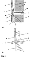
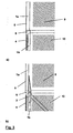
- FIGS. 1 a) and 2 a) are side views or in the FIGS. 1 b) and 2 B ) three - dimensional representations of a support pillar designed according to the invention, which differ from the in FIG. 3 illustrated and known from the prior art support column in particular differ in that they have a continuous hollow profile within the support column despite an S-shock, which extends in this case from a floor to a roof rack.
- Identical component components are provided with the same reference numerals in the figures.
- FIG. 1 is a part of a bus body skeleton shown in which an inventively designed support column 1 is provided, which takes over the function of a side wall pillar.
- the side wall pillar 1 represents as an outer boundary of a bus body skeleton for the statics of the body essential component, since at one end a roof rack and at the opposite end a bottom support are attached (not shown).
- 9 Bleckbeplankungen 5 and discs (not shown) are mounted by means of appropriate fasteners in the passenger area.
- divided sidewall column 1 is the in FIG. 1 illustrated sidewall column made in one piece and has a return in the central region in the form of a s-beat. By provided within the side wall pillar 1 return it is possible to make the sidewall column in one piece and at the same time to ensure that the sheet metal 5 and the surface of the trunk 10 limiting trunk lid 4 form a flat outer surface.
- a reinforcing element 3 is provided in the central region of the sidewall column 1.
- the reinforcing element 3 is executed hollow profile-like, disposed within the hollow profile element 2 and is connected in the upper and in the lower region via two perforated welds 13 with the hollow profile element 2.
- a longitudinal member 6 is attached, which ensures the rigidity of a Omnibusberippes in the longitudinal direction.
- a cross member 7 is fixed in this area, which serves as a console for the floor 8 of the passenger area 9.
- an inner lining 12 is provided, which is also attached to the side wall pillar 1 and ensures a clean completion of the passenger area 9.
- FIG. 2 is the same section of a bus body skeleton as in FIG. 1 shown in the region of the transition between passenger area 9 and trunk 10.
- the structure of the body tread with the straps, the floor, the trunk lid and the Blechbeklankungen corresponds to the in FIG. 1 ,
- the side wall pillar 1 has only one hollow profile element 2, which extends from one end of the pillar to the opposite end and which has a greater wall thickness in the middle region.
- the support column according to the invention it is possible to provide the column with a recess designed in the form of an S-turn, so that arranged on the side wall of a bus a one-piece sidewall column 1 without loss of security, comfort or appearance.
- FIG. 3 For comparison with the in the FIGS. 1 and 2 shown sidewall columns are in FIG. 3 illustrated two sidewall pillar variants of a bus, as known from the prior art.
- Essential feature of the sidewall columns in FIG. 3a and 3b is the two-part design.
- the side wall pillar 1 is divided into an upper and a lower pillar component to obtain a flat surface of the sheet metal panel 5 and the surface of the trunk lid 4.
- FIG. 3b illustrated support column has in addition to the upper and the lower pillar component 1 a, 1 b via an additional reinforcing element 3 that on the side wall pillar, for example.
- this additional component has to be connected to the lower pillar component 1b and, on the other hand, during the production of a bus body skeleton, a welded connection has to be established between the reinforcing element and the upper pillar component 1a.
- the production of such a weld is very expensive, since the seam is in the stress case in the region of the highest bending stress.
- FIGS. 3a 3b and 3b known from the prior art support columns thus represent in terms of safety and manufacturing costs only unsatisfactory technical solutions.
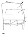
- FIG. 4 shows the behavior of a ring pant of a coach body skeleton in a load case, such as may occur during a tipping over of a bus in an accident.
- the boot space 10 which has a plurality of luggage compartment struts 11 for stiffening the skeleton.
- a cross member 7 On both sides of the cross member 7 is connected to a respective side wall column 1.
- the sidewall columns 1 are connected to each other at the upper ends via a roof rack 15.
- survival space 14 is shown in the interior of the passenger area 9.
- the dimensions of the survival space 14 are prescribed by law and should specify a space in which even in an accident, no objects penetrate.
- the Ringspant moves in the manner shown.
- bending stresses occur which, without provision of appropriate protective measures, have their maximum in the region of the attachment point of the cross member 7, so that in case of load the sidewall column 1 would be bent over in this area and would enter the transfer room 1.
- reinforcing elements 3 are provided in the region of the attachment points of the cross member 7, which ensure that in the load case, the maximum of the ratio of bending moment and moment of resistance occurring against bending upwards, ie moved towards the roof rack. If it then comes to bending or buckling of the side wall pillar, the column is bent over the attachment points of the cross member and at the same time approximately parallel to the lateral boundary of the survival space 14.
- a support column 1 which is both good to manufacture and assemble and meets all requirements for passenger safety ,
Landscapes
- Engineering & Computer Science (AREA)
- Chemical & Material Sciences (AREA)
- Combustion & Propulsion (AREA)
- Transportation (AREA)
- Mechanical Engineering (AREA)
- Body Structure For Vehicles (AREA)
- Rod-Shaped Construction Members (AREA)
Description
Die Erfindung betrifft eine Seitenwandsäule eines Omnibusses, die an gegenüberliegenden Enden mit jeweils einem Rahmenelement verbindbar ist und die ein geschlossenes, sich zwischen den beiden Enden erstreckendes Hohlprofilelement aufweist.The invention relates to a side wall pillar of a bus, which is connectable at opposite ends, each with a frame member and having a closed, extending between the two ends hollow profile element.
Karosseriegerippe, die aus einer Vielzahl von Seitenwandsäulen sowie Längs-, Quer-, Boden- und Dachträgern aufgebaut sind, sind im Fahrzeugbau hinlänglich bekannt und kommen vor allem im Omnibusbau vielfach zum Einsatz. Ein wesentliches Bauteil eines Karosseriegerippes stellt die Seitenwandsäule dar, die sowohl zum Tragen der Dach- und Bodenelemente als auch zur Befestigung von Fenstern sowie Blechbeplankungen vorgesehen ist. Damit die Blechbeplankungen im oberen Teil eines Omnisbusses und die Oberfläche der Kofferaumklappen eine ebene Fläche bilden, wird die Seitenwandsäule geteilt ausgeführt. Während der obere Teil der Seitenwandsäule im Karosserigerippe die Verbindung zwischen den Dachträgern und dem Längsprofil darstellt, verläuft der untere Teil der Seitenwandsäule leicht nach hinten versetzt vom Längsprofil aus zu den Bodenträgern. Darüber hinaus ist im Bereich des aus oberer und unterer Seitenwandsäule sowie des Längsprofils gebildeten Knotenpunkts üblicherweise eine Konsole vorgesehen, die als Auflage für den Fußboden dient.Bodywork skeleton, which are constructed from a variety of sidewall columns and longitudinal, transverse, floor and roof racks, are well known in the automotive industry and are mainly used in bus construction in many cases. An essential component of a body frame is the side wall pillar, which is intended both for supporting the roof and floor elements as well as for fastening windows and sheet metal. So that the sheet metal panels in the upper part of a Omnisbusses and the surface of the trunk flaps form a flat surface, the sidewall column is split. While the upper part of the sidewall pillar in the body rib represents the connection between the roof beams and the longitudinal profile, the lower part of the sidewall pillar is slightly offset rearwardly from the longitudinal profile to the floor beams. In addition, a console is provided in the region of the node formed from the upper and lower side wall pillar and the longitudinal profile, which serves as a support for the floor.
Die Einheit aus Seitenwandsäulen, Dach- sowie Boden- bzw. Fußbodenelemente tragenden Querträgern bilden einen sogenannten Ringspant, der während der Fahrt Schwingungsbelastungen und Biegebeanspruchungen, insbesondere bei einem Unfall, ausgesetzt sein kann. Um trotz immer leichter werdender Bauweisen im Fahrzeugbau die Sicherheitsanforderungen zu erfüllen, werden bei Karosseriegerippen, bspw. auch an dem Knotenpunkt Seitenwandsäule/Längsprofil/Fußbodenauflage spezielle Einbauten vorgesehen, die die Seitenwand lokal verstärken oder in Form von Winkelelementen zwischen angrenzende Träger angebracht werden.The unit of sidewall columns, roof and floor or floor elements supporting cross members form a so-called annular frame, which can be exposed to vibration loads and bending stresses during the ride, especially in an accident. In order to meet the safety requirements despite ever-lighter construction methods in vehicle construction, in the case of bodywork ribs, For example, also provided at the junction sidewall pillar / longitudinal profile / floor support special fittings that strengthen the side wall locally or attached in the form of angle elements between adjacent support.
Eine derartige Knotenverstärkung für Gerippestrukturen von Nutzfahrzeugen ist bspw. aus der
Ferner ist aus der
Neben den vorbeschriebenen Problemen stellt sich im Fahrzeugbau häufig das Problem, dass der für eine Verstärkung benötigte Platz nicht zur Verfügung steht, da die Verstärkung bspw. in den Fußraum des Fahrgastbereiches hineinragt und somit den Fahrgast beeinträchtigen würde.In addition to the problems described above, the problem often arises in vehicle construction that the space required for a reinforcement is not available, since the reinforcement protrudes, for example, into the footwell of the passenger area and thus would impair the passenger.
Ausgehend von dem bekannten Stand der Technik liegt der Erfindung daher die Aufgabe zu Grunde, eine Tragsäule für ein Karosseriegerippe eines Kraftfahrzeugs anzugeben, die die Sicherheitsanforderungen, insbesondere in Bezug auf den innerhalb der Fahrgastzelle erforderlichen Überlebensraum erfüllt, und gleichzeitig kostengünstig und mit verhältnismäßig geringem fertigungstechnischen Aufwand herzustellen ist. Darüber hinaus soll die Tragsäule möglichst platzsparend ausgeführt sein, damit der einer Nutzung zur Verfügung stehende Raum nicht eingeschränkt wird.Based on the known prior art, the invention is therefore based on the object to provide a support column for a bodywork skeleton of a motor vehicle, which meets the safety requirements, in particular with respect to the required inside the passenger compartment survival space, and at the same time cost and with relatively low manufacturing expense is to produce. In addition, the support column should be designed to save space, so that the space available for use is not limited.
Die der Erfindung zu Grunde liegende Aufgabe wird mit einer Seitenwand säule gemäß Patentanspruch 1 gelöst. Vorteilhafte Weiterbildungen des Erfindungsgedankens sind Gegenstand der Unteransprüche sowie aus dem nachfolgenden Beschreibungstext und den Ausführungsbeispielen zu entnehmen.The problem underlying the invention is achieved with a side wall column according to
Die Erfindung betrifft eine Seitenwandsäule eines Omnibusses, die an gegenüberliegenden Enden mit jeweils wenigstens einem Karosserieelement verbindbar ist und die ein sich zwischen den beiden Enden ersteckendes Hohlprofilelement (2) aufweist, das einstückig ausgeführt ist und eine Längsmittenachse aufweist, die gekrümmt ist oder zumindest zwei nicht parallele Abschnitte aufweist, wobei sich an die gegenüberliegenden Enden äußere Säulenabschnitte anschließen, zwischen denen ein mittlerer Säulenabschnitt vorgesehen ist, und die sich dadurch auszeichnet, dass die Längsmittenachse im Bereich des mittleren Säulenabschnitts, der die beiden äußeren Säulenabschnitte verbindet, gekrümmt ist oder zumindest zwei nicht parallele Abschnitte aufweist und der mittlere Säulenabschnitt in wenigstens einer Beanspruchungsrichtung über ein größeres Widerstandsmoment gegen Biegung als die äußeren Säulenabschnitte verfügt wobei im Bereich des mittleren Säulenabschnittes wenigstens ein Verstärkungselement vorgesehen ist, das zumindest abschnittsweise einen Kontaktbereich mit dem Hohlprofilelement aufweist und das innerhalb des Hohlprofilelements angeordnet ist.The invention relates to a side wall pillar of a bus, which is connectable at opposite ends with at least one body element and which has a hollow profile element (2) extending between the two ends, which is made in one piece and has a longitudinal center axis which is curved or at least not two having parallel portions, wherein at the opposite ends outer pillar portions connect, between which a central pillar portion is provided, and which is characterized in that the longitudinal center axis in the region of the central pillar portion connecting the two outer pillar portions is curved, or at least two not has parallel sections and the central column section in at least one direction of stress has a greater moment of resistance to bending than the outer column sections, wherein in the region of the central column section least s a reinforcing element is provided, which has at least partially a contact area with the hollow profile element and which is disposed within the hollow profile element.
Um das Widerstandsmoment der Tragsäule im mittleren Säulenabschnitt zu erhöhen, wird der wirksame Querschnitt der Säule in diesem Bereich vergrößert und/oder die Werkstoffeigenschaften entsprechend verbessert. Dies geschieht wahlweise durch das Vorsehen eines zusätzlichen Verstärkungselementes, den abschnittsweisen Einsatz eines Werkstoffes höherer Güte und/oder die Auswahl einer gegenüber den äußeren Säulensbschnitten größeren Wandstärke des Hohlprofilelementes im mittleren Säulenabschnitt. Neben dem Einsatz eines Werkstoffes höherer Güte im mittleren Säulensbschnitt ist es selbstverständlich auch denkbar, den für das Hohlprofilelement in diesem Bereich vorgesehenen Werkstoff derart zu vergüten, dass dieser über verbesserte Werkstoffeigenschaften verfügt.In order to increase the moment of resistance of the support column in the middle column section, the effective cross section of the column in this area is increased and / or the material properties are correspondingly improved. This is done either by the provision of an additional reinforcing element, the sectional use of a material of higher quality and / or the selection of a relation to the outer column sections greater wall thickness of the hollow profile element in the central column section. In addition to the use of a material of higher quality in the middle column section, it is of course also conceivable to compensate for the material provided for the hollow profile element in this area in such a way that it has improved material properties.
Mit der Erfindung wird damit zum einen eine Tragsäule für ein Karosseriegerippe eines Kraftfahrzeugs realisiert, die auf Grund der speziellen Form in Bereichen einsetzbar ist, in denen die Platzverhältnisse beengt sind. Zum anderen wird durch die einstückige Ausführung des Hohlprofilelementes und die Verstärkung der Tragsäule im mittleren Säulenbereich eine einfache Herstellung und Montage bzw. Befestigung der Säule in einem Karosseriegerippe sicher gestellt, ohne dass hierbei Einbußen bezüglich der Festigkeit und Steifigkeit hingenommen werden müssen. Darüber hinaus wird mit der erfindungsgemäßen Tragsäule ein Trägerelement zur Verfügung gestellt, das auch an Verbindungsknoten, bspw. an einem Längsträger eines Omnibus Karosseriegerippes nicht geteilt werden muss, sondern auf Grund seiner Form einstückig an dem Träger vorbeiführbar ist. Somit ermöglicht die erfindungsgemäße Lösung den flexiblen Einsatz hochfester Tragsäulen an verschiedenen Stellen eines Karosseriegerippes auch unter Berücksichtigung spezieller konstruktiver Anforderungen.With the invention, on the one hand, a support column for a bodywork skeleton of a motor vehicle is realized, which can be used due to the special shape in areas in which the space is cramped. On the other hand, the one-piece design of the hollow profile element and the reinforcement of the support column in the central column area ensure easy manufacture and assembly or attachment of the column in a body skeleton, without sacrificing strength and rigidity. In addition, a carrier element is provided with the support column according to the invention, which also at connection nodes, for example. On a longitudinal member of a bus Karosseriegerippes does not have to be shared, but due to its shape is integrally fed past the carrier. Thus, the solution according to the invention allows the flexible use of high-strength support columns at various points of a body frame, taking into account special design requirements.
Das sich zwischen den Enden der Tragsäule in Längsrichtung erstreckende Hohlprofilelement ist einstückig ausgeführt. Dies bedeutet, dass es sich bei dem Hohlprofilelement entweder um ein Bauteil handelt oder dass das Hohlprofilelement noch vor Einbau in ein Karosseriegerippe aus mehreren Bauelementen, bspw. durch Schweißen, zu einem einstückigen Bauteil zusammengefügt worden ist. Von Bedeutung hierbei ist lediglich, dass die Tragsäule im Moment des Einbaus in ein Karosseriegerippe als ein Bauteil zur Verfügung steht, damit die entsprechende Säule einfach in das Gerippe einsetzbar und mit den entsprechenden Karosserielementen verbindbar ist. Die Tragsäule ist an gegenüberliegenden Enden mit Karosserieelementen, wie etwa einem Boden- sowie einem Dachträger zu verbinden. Dies schließt allerdings nicht aus, dass die Tragsäule mit weiteren Karosserielementen verbunden wird. So ist es etwa denkbar, dass im mittleren Säulenbereich Konsolen als Halterungen eines Zwischenbodens befestigt werden oder dass zumindest abschnittsweise eine Beplankung an der Tragsäule angebracht wird.The extending between the ends of the support column in the longitudinal direction hollow profile element is made in one piece. This means that the hollow profile element is either a component or that the hollow profile element has been assembled to a one-piece component before installation in a body skeleton of a plurality of components, for example. By welding. Of importance here is only that the support column is at the moment of installation in a body frame as a component available, so that the corresponding column can be easily inserted into the skeleton and connected to the corresponding body elements. The support column is to be connected at opposite ends with body elements, such as a floor and a roof rack. However, this does not exclude that the support column is connected to other body elements. So it is conceivable, for example, that in the central column area brackets are attached as brackets of a false floor or that at least in sections, a planking is attached to the support column.
In einer speziellen Ausführungsform ist die Tragsäule gedanklich in drei Abschnitte unterteilbar, von denen die äußeren Säulenabschnitte vorzugsweise jeweils zumindest teilweise in parallel zu einander angeordneten Ebenen liegen. Der mittlere Säulenabschnitt ist bei einer solchen Säule derart geformt, dass dieser Abschnitt das Verbindungselement zwischen den beiden äußeren Säulenabschnitten darstellt. Hierzu verfügt der mittlere Säulenabschnitt über zwei Enden, die jeweils mit den äußeren Säulenabschnitten verbunden sind und somit zumindest eine Ebene berühren, in der die äußeren Säulenabschnitte, bzw. zumindest die dem mittleren Säulenabschnitt zugewandten Endbereiche der äußeren Säulenabschnitte, angeordnet sind.In a special embodiment, the support column can theoretically be subdivided into three sections, of which the outer column sections preferably each lie at least partially in planes arranged parallel to one another. The central column section is formed in such a column so that this section constitutes the connecting element between the two outer column sections. For this purpose, the central pillar portion has two ends, which are respectively connected to the outer pillar portions and thus at least contact a plane in which the outer pillar portions, or at least the middle pillar portion facing end portions of the outer pillar portions are arranged.
Das Hohlprofilelement der erfindungsgemäßen Tragsäule verfügt vorzugsweise über einen wenigstens nahezu rechteckigen, insbesondere 60 x 40 mm2 großen Querschnitt. Es ist aber auch denkbar, dass der Querschnitt eine andere mehreckige oder sogar runde Kontur aufweist. Eine weitere besondere Ausführungsform sieht ein Hohlprofilelement mit einem quadratischen Querschnitt mit bevorzugten Abmessungen von 40 x 40, 50 x 50 oder 80 x 80 mm2 vor.The hollow profile element of the support column according to the invention preferably has an at least approximately rectangular, in particular 60 × 40 mm 2, large cross section. But it is also conceivable that the cross section has another polygonal or even round contour. A further particular embodiment provides a hollow profile element with a square cross section with preferred dimensions of 40 × 40, 50 × 50 or 80 × 80 mm 2 .
Als Hohlprofilelement kommen insbesondere Bauelemente in Frage, die über eine Wandstärke von mindestens 2 mm verfügen. Als Werkstoff ist die Verwendung eines hochfesten Stahls mit einer Mindesttreckgrenze von 420 N/mm2, vorzugsweise vonAs a hollow profile element in particular components in question, which have a wall thickness of at least 2 mm. The material is the use of a high-strength steel with a minimum yield strength of 420 N / mm 2 , preferably from
S 460, besonders geeignet. Es ist allerdings auch denkbar andere Werkstoffe, die die vorgenannte Anforderung bzgl. der Mindestsreckgrenze erfüllen und wie stahlartige Werkstoffe zu verarbeiten sind, für das Hohlprofilelement einzusetzen.S 460, especially suitable. However, it is also conceivable other materials that meet the aforementioned requirement with respect to the minimum yield strength and how to use steel-like materials to use for the hollow profile element.
In einer weiteren besonderen Ausführungsform der erfindungsgemäßen Tragsäule verfügt das Hohlprofilelement im Bereich des mittleren Säulenabschnittes wenigstens teilweise über eine größere Wandstärke als im Bereich der äußeren Säulenabschnitte. Die Wandstärke des Hohlprofils wird in diesem Fall derart verstärkt, das der mittlere Säulenabschnitt der erfindungsgemäßen Tragsäule in zumindest einer möglichen Beanspruchungsrichtung ein größeres Widerstandmoment gegen Biegung als die äußeren Säulenabschnitte aufweist. Neben einer Erhöhung der Wandstärke ist es ferner möglich, im mittleren Säulenabschnitt wenigstens ein zusätzliches Verstärkungselement vorzusehen, das außerhalb, etwa als Manschette, oder innerhalb des Hohlprofils derart angeordnet wird, dass wenigstens abschnittsweise eine Kontaktfläche zwischen Hohlprofil und Verstärkungselement gebildet wird. Hierbei ist es sogar denkbar, das Verstärkungselement mehrfach geschachtelt, also indem mehrere Hohlprofile über- bzw. ineinander gesteckt werden, auszuführen. In jedem Fall ist sicher zu stellen, dass das Hohlprofil und das wenigstens eine Verstärkungselement im Bereich der Kontaktfläche eine innige Verbindung eingehen. Zur Herstellung einer solchen Verbindung sind annähernd alle bekannten Verbindungstechniken geeignet. So können hierfür sowohl Fertigungsverfahren wie Löten, Kleben, Schweißen oder Nieten eingesetzt werden, die zur Herstellung der Verbindung einen Hilfsstoff benötigen, als auch Verfahren wie Biegen, Pressen oder Ein- bzw. Aufschrumpfen, mit denen eine formschlüssige Verbindung zwischen dem Hohlprofil- und dem Verstärkungselement erzeugt wird. In einer ganz besonders geeigneten Ausführungsform der erfindungsgemäßen Tragsäule wird das Verstärkungselement mit Hilfe von Lochschweißungen mit dem Hohlprofilelement verbunden.In a further particular embodiment of the support column according to the invention, the hollow profile element in the region of the central column section at least partially has a greater wall thickness than in the region of the outer column sections. The wall thickness of the hollow profile is reinforced in this case such that the middle column section of the support column according to the invention has a greater resistance to bending than the outer column sections in at least one possible stress direction. In addition to an increase in the wall thickness, it is also possible to provide at least one additional reinforcing element in the central column section, which is arranged outside, for example as a sleeve, or within the hollow profile such that at least in sections a contact surface between the hollow profile and reinforcing element is formed. In this case, it is even conceivable to nested the reinforcing element several times, that is, by putting several hollow profiles over or into one another. In any case, it must be ensured that the hollow profile and the at least one reinforcing element form an intimate connection in the region of the contact surface. Almost all known joining techniques are suitable for producing such a compound. For this purpose, both manufacturing processes such as soldering, gluing, welding or Rivets are used, which require an adjuvant for the preparation of the compound, as well as methods such as bending, pressing or shrink-in or shrink, with which a positive connection between the hollow profile and the reinforcing element is generated. In a particularly suitable embodiment of the support column according to the invention, the reinforcing element is connected by means of plug welds with the hollow profile element.
Alternativ zu der vorbeschriebenen Variante, das Widerstandsmoment gegen Biegung im mittleren Säulenabschnitt im Vergleich zu den äußeren Säulenabschnitten wenigstens teilweise zu erhöhen, ist es selbstverständlich auch denkbar, im mittleren Säulenabschnitt ein Verstärkungselement vorzusehen und ein Hohlprofil mit annähernd konstanter Wandstärke zu wählen. Für die Verbindung des Hohlprofilelementes mit dem Verstärkungselement sind auch bei dieser speziellen Ausführungsform die bereits beschriebenen Verbindungstechniken einsetzbar.As an alternative to the above-described variant, to at least partially increase the resistance moment against bending in the middle column section in comparison to the outer column sections, it is of course also conceivable to provide a reinforcing element in the central column section and to select a hollow profile with approximately constant wall thickness. For the connection of the hollow profile element with the reinforcing element, the connection techniques already described can also be used in this particular embodiment.
Eine weitere, ganz besonders geignete Ausführungsform der erfindungsgemäßen Tragsäule zeichnet sich dadurch aus, dass das Verstärkungselement im mittleren Säulenabschnitt innerhalb des Hohlprofilelementes angeordnet ist und hohlprofilartig, insbesondere mit einem rechteckigen bzw. sogar quadratischen Querschnitt, ausgebildet ist. Selbstverständlich ist es überdies möglich, einen anderen, mehreckigen oder auch runden Querschnitt für das hohlprofilartige Verstärkungselement zu wählen. Darüber hinaus sieht eine alternative Ausführungsform der erfindungsgemäßen Tragsäule vor, das Verstärkungselement in Form eines T-, Doppel-T-, I-, U- oder L-Profils auszubilden. Auch das Verstärkungselement weist vorzugsweise zumindest teilweise einen hochfesten Stahl mit einer Mindeststreckgrenze von 420 N/mm2, insbesondere S 460, auf. In diesem Zusammenhang ist es besonders geeignet, für die gesamte Tragsäule, also insbesondere für das Hohlprofil- und für das Verstärkungselement den gleichen Werkstoff zu wählen.Another, particularly suitable embodiment of the support column according to the invention is characterized in that the reinforcing element is arranged in the central column section within the hollow profile element and a hollow profile, in particular with a rectangular or even square cross-section is formed. Of course, it is also possible to choose a different, polygonal or round cross section for the hollow profile-like reinforcing element. In addition, an alternative embodiment of the support column according to the invention provides to form the reinforcing element in the form of a T, double T, I, U or L profile. Also, the reinforcing element preferably comprises at least partially a high-strength steel with a minimum yield strength of 420 N / mm 2 , in particular S 460, on. In this context, it is particularly suitable to choose the same material for the entire support column, ie in particular for the hollow profile and for the reinforcing element.
In einer weiteren besonders geeigneten Ausführungsform der erfindungsgemäßen Tragsäule wird eine überaus exakte Anpassung des Widerstandsmoments gegen Biegung durch die Anordnung einer Mehrzahl bzw. eine Kombination verschiedener Elemente der bereits beschriebenen Verstärkungselemente in einer Tragsäule erreicht.In a further particularly suitable embodiment of the support column according to the invention a very exact adaptation of the resistance torque against bending by the arrangement of a plurality or a combination of different Achieved elements of the reinforcing elements already described in a support column.
Die vorliegende Tragsäule für ein Karosseriegerippe eines Kraftfahrzeugs wird nachfolgend an Hand von Ausführungsbeispielen ohne Beschränkung des allgemeinen Erfindungsgedankens beschrieben. Hierbei zeigen:
- Fig. 1
- Tragsäule mit Verstärkungselement
- Fig. 2
- einstückige Tragsäule mit verstärktem Mittelbereich
- Fig. 3
- Tragsäule aus dem Stand der Technik
- Fig. 4
- Ringspant eines Karosseriegerippes im Belastungsfall
- Fig. 1
- Support pillar with reinforcing element
- Fig. 2
- one-piece support column with reinforced middle section
- Fig. 3
- Support column from the prior art
- Fig. 4
- Ringspant a body skeleton under load case
In den
In
Um neben den fertigungstechnischen Vorteilen bei der Verwendung einer einstückigen Tragsäule als Seitenwandsäule 1, auch die Sicherheit eines Omnibus-Karosseriegerippes gewährleisten zu können, ist im mittleren Bereich der Seitenwandsäule 1, ein Verstärkungselement 3 vorgesehen. Das Verstärkungselement 3 ist hohlprofilartig ausgeführt, innerhalb des Hohlprofilelements 2 angeordnet und ist im oberen sowie im unteren Bereich über jeweils zwei Lochschweißverbindungen 13 mit dem Hohlprofilelement 2 verbunden.In addition to the manufacturing advantages in the use of a one-piece support column as a
Ferner ist an der Außenseite im mittleren Bereich der Seitenwandsäule 1 ein Längsträger 6 befestigt, der die Steifigkeit eines Omnibusberippes in Längsrichtung sicher stellt. Auf der Innenseite der Seitenwandsäule ist in diesem Bereich ein Querträger 7 befestigt, der als Konsole für den Fußboden 8 des Fahrgastbereiches 9 dient. Um den Fahrgastbereich 9 darüber hinaus auch gegen das Karosseriegerippe abzugrenzen ist eine Innenverkleidung 12 vorgesehen, die ebenfalls an der Seitenwandsäule 1 befestigt ist und für einen sauberen Abschluß des Fahrgastbereiches 9 sorgt.Further, on the outer side in the central region of the
In
Zum Vergleich mit den in den
Die in
Die in den
Darüber hinaus ist im Inneren des Fahrgastbereiches 9 der sogenannte Überlebensraum 14 dargestellt. Die Abmessungen des Überlebensraums 14 sind vom Gesetzgeber vorgeschrieben und sollen einen Raum festlegen, in den auch bei einem Unfall keine Gegenstände eindringen. Wird der in
Durch das Vorsehen einer einstückigen Seitenwandsäule, in der das Verstärkungselement 3, wie bereits eingehend erläutert, angeordnet wird, läßt sich daher auf besonders bevorzugte Weise eine Tragsäule 1 erzeugen, die sowohl gut zu fertigen bzw. montieren ist als auch alle Anforderungen an die Fahrgastsicherheit erfüllt.By providing a one-piece sidewall column, in which the reinforcing
- 11
- Tragsäulesupport column
- 1a1a
- oberes SäulenbauelementUpper pillar component
- 1b1b
- unteres Säulenbauelementlower column component
- 22
- HohlprofilelementSectional element
- 33
- VertstärkungselementVertstärkungselement
- 44
- KofferraumklappeTrunk lid
- 55
- Blechbeplankungplanking
- 66
- Längsträgerlongitudinal beams
- 77
- Querträgercrossbeam
- 88th
- Fußbodenfloor
- 99
- Fahrgastbereichpassenger area
- 1010
- Kofferraumtrunk
- 1111
- KofferraumstrebenTrunk struts
- 1212
- Innenverkleidunginterior panelling
- 1313
- Lochschweißungplug welding
- 1414
- ÜberlebensraumAbout Habitat
- 1515
- Dachträgerroof rack
Claims (13)
- Side wall column of a bus that can be connected by its opposite ends with at least one body element in each case and has a hollow profile element (2), which element (2) extends between the two ends, is of a one-piece design and has a longitudinal centre axis that is bent or at least has two non-parallel sections, with outer column sections being connected to the opposite ends and a central column section being provided between them,
characterised in that the longitudinal centre axis is bent in the area of the central column section that connects the two outer column sections or at least has two non-parallel sections and the central column section has a higher section modulus against bending in at least one stress direction than the outer column sections, with at least one reinforcement element being provided in the area of the central column section, which element, at least in part, has an area of contact with the hollow profile element and is arranged within the hollow profile element. - Supporting column according to Claim 1, characterised in that the hollow profile element (2) has an at least almost rectangular cross-section.
- Supporting column according to Claim 1 or 2, characterised in that the hollow profile element (2) has a wall thickness of at least 2 mm.
- Supporting column according to one of Claims 1 to 3, characterised in that the hollow profile element (2) at least partially has a high-strength steel with a minimum yield strength of at least 420 N/mm2, preferably S 460.
- Supporting column according to one of Claims 1 to 4, characterised in that the hollow profile element (2) at least partially has a greater wall thickness in the area of the central column section than in the area of the outer column sections.
- Supporting column according to one of Claims 1 to 5, characterised in that the reinforcement element (3) is designed as a hollow profile.
- Supporting column according to one of Claims 1 to 6, characterised in that the reinforcement element (3) has an at least almost rectangular cross-section.
- Supporting column according to one of Claims 1 to 7, characterised in that the reinforcement element (3) has a round cross-section.
- Supporting column according to claim 1, characterised in that the reinforcement element (3) is designed in the form of a T, double T, I, U or L profile.
- Supporting column according to one of Claims 1 to 9, characterised in that the reinforcement element (3) at last partially has a high-strength steel with a minimum yield strength of at least 420 N/mm2, preferably S 460.
- Supporting column according to one of Claims 1 to 10, characterised in that the hollow profile element (2) has an S deflection or two kinks in the area of the central column section.
- Supporting column according to one of Claims 1 to 11, characterised in that the reinforcement element (3) is fastened to the hollow profile element (2) by means of welded and/or riveted joints.
- Supporting column according to one of Claims 1 to 12, characterised in that the reinforcement element (3) is connected to the hollow profile element (2) by means of at least one plug-welded joint (13).
Priority Applications (1)
| Application Number | Priority Date | Filing Date | Title |
|---|---|---|---|
| PL04021407T PL1516802T5 (en) | 2003-09-17 | 2004-09-09 | Side wall pillar of a bus |
Applications Claiming Priority (2)
| Application Number | Priority Date | Filing Date | Title |
|---|---|---|---|
| DE10342842.9A DE10342842B4 (en) | 2003-09-17 | 2003-09-17 | Support column for a body skeleton |
| DE10342842 | 2003-09-17 |
Publications (4)
| Publication Number | Publication Date |
|---|---|
| EP1516802A2 EP1516802A2 (en) | 2005-03-23 |
| EP1516802A3 EP1516802A3 (en) | 2006-05-31 |
| EP1516802B1 true EP1516802B1 (en) | 2008-12-31 |
| EP1516802B2 EP1516802B2 (en) | 2013-04-10 |
Family
ID=34177785
Family Applications (1)
| Application Number | Title | Priority Date | Filing Date |
|---|---|---|---|
| EP04021407.4A Expired - Lifetime EP1516802B2 (en) | 2003-09-17 | 2004-09-09 | Side wall pillar of a bus |
Country Status (5)
| Country | Link |
|---|---|
| EP (1) | EP1516802B2 (en) |
| CN (1) | CN100457530C (en) |
| DE (2) | DE10342842B4 (en) |
| ES (1) | ES2316906T5 (en) |
| PL (1) | PL1516802T5 (en) |
Cited By (1)
| Publication number | Priority date | Publication date | Assignee | Title |
|---|---|---|---|---|
| EP4721891A1 (en) | 2024-10-01 | 2026-04-08 | voestalpine Krems GmbH | Vehicle with a cabin, this cabin with a profile and this profile |
Family Cites Families (14)
| Publication number | Priority date | Publication date | Assignee | Title |
|---|---|---|---|---|
| DE59501217D1 (en) * | 1995-03-22 | 1998-02-12 | Porsche Ag | Hollow profile for a support structure of a motor vehicle |
| DE19519353A1 (en) | 1995-05-26 | 1996-11-28 | Porsche Ag | Carrier of a vehicle body structure and method for its production |
| DE19638904A1 (en) | 1996-09-23 | 1998-03-26 | Bayerische Motoren Werke Ag | Process for producing a hollow beam for vehicle bodies |
| DE19644047A1 (en) * | 1996-10-31 | 1998-05-07 | Bayerische Motoren Werke Ag | Side column for body of motor vehicle |
| DE19818260B4 (en) * | 1998-04-23 | 2008-08-21 | Volkswagen Ag | Body pillar, in particular B pillar, for a motor vehicle |
| DE19829832B4 (en) * | 1998-07-03 | 2008-03-27 | Volkswagen Ag | Body structure for a motor vehicle |
| DE19903724A1 (en) * | 1999-01-30 | 2000-08-03 | Porsche Ag | Carcass for large capacity vehicles, and especially omnibuses, has large volume hollow profiles with not-completely symmetrical cross section forming pillars and longitudinal and transverse beams of main frame |
| DE19903722A1 (en) * | 1999-01-30 | 2000-08-03 | Porsche Ag | Body side wall for large capacity motor vehicles, such as omnibuses, has preformed metal sheets conforming to body's contour and forming side wall skin fastened to carcass directly and indirectly by different joint connections |
| DE19929219B4 (en) | 1999-06-25 | 2009-02-26 | Man Nutzfahrzeuge Ag | Node reinforcement for skeleton structures in superstructures of commercial vehicles |
| EP1227968B1 (en) * | 1999-10-28 | 2004-01-14 | Toyota Jidosha Kabushiki Kaisha | Vehicle pillar structure |
| DE10002617A1 (en) * | 2000-01-22 | 2001-07-26 | Volkswagen Ag | Body element with reinforcement plate |
| DE10015325A1 (en) * | 2000-03-28 | 2001-10-04 | Volkswagen Ag | Body component made of steel |
| DE10126183A1 (en) | 2001-05-30 | 2002-12-12 | Karmann Gmbh W | Device for increasing the strength of a hollow molded part of a vehicle body |
| DE10232320A1 (en) | 2002-07-17 | 2004-02-05 | Bayerische Motoren Werke Ag | Vehicle body with a B-pillar |
-
2003
- 2003-09-17 DE DE10342842.9A patent/DE10342842B4/en not_active Expired - Lifetime
-
2004
- 2004-09-09 DE DE502004008762T patent/DE502004008762D1/en not_active Expired - Lifetime
- 2004-09-09 PL PL04021407T patent/PL1516802T5/en unknown
- 2004-09-09 ES ES04021407T patent/ES2316906T5/en not_active Expired - Lifetime
- 2004-09-09 EP EP04021407.4A patent/EP1516802B2/en not_active Expired - Lifetime
- 2004-09-17 CN CNB2004100471612A patent/CN100457530C/en not_active Expired - Lifetime
Cited By (2)
| Publication number | Priority date | Publication date | Assignee | Title |
|---|---|---|---|---|
| EP4721891A1 (en) | 2024-10-01 | 2026-04-08 | voestalpine Krems GmbH | Vehicle with a cabin, this cabin with a profile and this profile |
| WO2026074043A1 (en) | 2024-10-01 | 2026-04-09 | Voestalpine Krems Gmbh | Vehicle having a cabin, said cabin having a profile, and said profile |
Also Published As
| Publication number | Publication date |
|---|---|
| ES2316906T3 (en) | 2009-04-16 |
| CN1640747A (en) | 2005-07-20 |
| ES2316906T5 (en) | 2013-06-04 |
| EP1516802A2 (en) | 2005-03-23 |
| EP1516802A3 (en) | 2006-05-31 |
| EP1516802B2 (en) | 2013-04-10 |
| PL1516802T3 (en) | 2009-06-30 |
| DE502004008762D1 (en) | 2009-02-12 |
| CN100457530C (en) | 2009-02-04 |
| PL1516802T5 (en) | 2013-11-29 |
| DE10342842A1 (en) | 2005-04-28 |
| DE10342842B4 (en) | 2018-04-19 |
Similar Documents
| Publication | Publication Date | Title |
|---|---|---|
| DE10040824B4 (en) | Steering column support beam structure | |
| DE10108287B4 (en) | body structure | |
| DE4208700C2 (en) | Stem construction for vehicles | |
| EP1840003B1 (en) | Door sill reinforcing element for a car body | |
| DE69708009T2 (en) | vehicle body | |
| EP2483136B1 (en) | Vehicle body structure having a body reinforcement behind the second row of seats | |
| EP0760329B1 (en) | Assembley of side panels of motor car bodies | |
| EP1525132B1 (en) | Floor-supporting arrangement in motor vehicles | |
| EP0749890B1 (en) | Monocoque construction body-in-white for a motor vehicle and procedure for its manufacturing | |
| EP1738943B1 (en) | Door structure of a motor vehicle | |
| EP2390164B1 (en) | Vehicle bodywork in a metal sheet heel area of a passenger cabin | |
| DE102016209186B3 (en) | Body structure for a motor vehicle | |
| DE102010051783A1 (en) | Body for passenger car, has main floor plate, longitudinal beams and cross beams designed as hybrid device with central region and rear portion made of steel, and lateral flange regions, front region and edge area made of light metal alloy | |
| EP0989052A2 (en) | Reinforcement for an integral body and frame of a vehicle | |
| DE102020209517A1 (en) | Vehicle body | |
| WO2011032715A1 (en) | Vehicle bodywork structure in the floor region of the occupant compartment and associated manufacturing method | |
| DE102009041315A1 (en) | A-shaped column for motor vehicles, particularly passenger cars, has outer part and inner part connected with outer part, where outer part is formed as profile component, particularly aluminum-based alloy | |
| EP0774401A2 (en) | Front part for automotive vehicles incorporating a support structure | |
| EP0896919A2 (en) | Transverse support beam for the steering column in a motor vehicle, in particular in a car | |
| DE102010021137A1 (en) | Body component for motor vehicle, particularly passenger car, has bonded blank, particular customized plate with two laminar subareas made from different metal alloys | |
| DE102007032246B4 (en) | Motor vehicle body with side sills | |
| DE102013019591A1 (en) | Coupling structure for coupling roof section with side section of vehicle i.e. motor car, has roof cross beam whose edge portion is connected to two sides of bead having upper edge portion and inner roof longitudinal carrier | |
| DE10023506B4 (en) | Cockpit carrier for the body of a motor vehicle | |
| DE102005045781B4 (en) | frame structure | |
| DE102005011834B4 (en) | Lateral roof frame for a motor vehicle |
Legal Events
| Date | Code | Title | Description |
|---|---|---|---|
| PUAI | Public reference made under article 153(3) epc to a published international application that has entered the european phase |
Free format text: ORIGINAL CODE: 0009012 |
|
| AK | Designated contracting states |
Kind code of ref document: A2 Designated state(s): AT BE BG CH CY CZ DE DK EE ES FI FR GB GR HU IE IT LI LU MC NL PL PT RO SE SI SK TR |
|
| AX | Request for extension of the european patent |
Extension state: AL HR LT LV MK |
|
| PUAL | Search report despatched |
Free format text: ORIGINAL CODE: 0009013 |
|
| AK | Designated contracting states |
Kind code of ref document: A3 Designated state(s): AT BE BG CH CY CZ DE DK EE ES FI FR GB GR HU IE IT LI LU MC NL PL PT RO SE SI SK TR |
|
| AX | Request for extension of the european patent |
Extension state: AL HR LT LV MK |
|
| 17P | Request for examination filed |
Effective date: 20061125 |
|
| AKX | Designation fees paid |
Designated state(s): AT BE BG CH CY CZ LI |
|
| 17Q | First examination report despatched |
Effective date: 20070202 |
|
| RBV | Designated contracting states (corrected) |
Designated state(s): DE ES FR IT PL SE TR |
|
| REG | Reference to a national code |
Ref country code: DE Ref legal event code: 8566 |
|
| GRAP | Despatch of communication of intention to grant a patent |
Free format text: ORIGINAL CODE: EPIDOSNIGR1 |
|
| RTI1 | Title (correction) |
Free format text: SIDE WALL PILLAR OF A BUS |
|
| GRAS | Grant fee paid |
Free format text: ORIGINAL CODE: EPIDOSNIGR3 |
|
| GRAA | (expected) grant |
Free format text: ORIGINAL CODE: 0009210 |
|
| AK | Designated contracting states |
Kind code of ref document: B1 Designated state(s): DE ES FR IT PL SE TR |
|
| REF | Corresponds to: |
Ref document number: 502004008762 Country of ref document: DE Date of ref document: 20090212 Kind code of ref document: P |
|
| REG | Reference to a national code |
Ref country code: SE Ref legal event code: TRGR |
|
| REG | Reference to a national code |
Ref country code: ES Ref legal event code: FG2A Ref document number: 2316906 Country of ref document: ES Kind code of ref document: T3 |
|
| REG | Reference to a national code |
Ref country code: PL Ref legal event code: T3 |
|
| PLBI | Opposition filed |
Free format text: ORIGINAL CODE: 0009260 |
|
| PLAZ | Examination of admissibility of opposition: despatch of communication + time limit |
Free format text: ORIGINAL CODE: EPIDOSNOPE2 |
|
| 26 | Opposition filed |
Opponent name: DAIMLER AG Effective date: 20090930 |
|
| PLBA | Examination of admissibility of opposition: reply received |
Free format text: ORIGINAL CODE: EPIDOSNOPE4 |
|
| PLAX | Notice of opposition and request to file observation + time limit sent |
Free format text: ORIGINAL CODE: EPIDOSNOBS2 |
|
| PLBB | Reply of patent proprietor to notice(s) of opposition received |
Free format text: ORIGINAL CODE: EPIDOSNOBS3 |
|
| PLAY | Examination report in opposition despatched + time limit |
Free format text: ORIGINAL CODE: EPIDOSNORE2 |
|
| PLBC | Reply to examination report in opposition received |
Free format text: ORIGINAL CODE: EPIDOSNORE3 |
|
| REG | Reference to a national code |
Ref country code: FR Ref legal event code: CD |
|
| REG | Reference to a national code |
Ref country code: ES Ref legal event code: PC2A Owner name: "MAN TRUCK & Effective date: 20110620 Ref country code: ES Ref legal event code: PC2A Owner name: MAN TRUCK & BUS AG Effective date: 20110620 |
|
| REG | Reference to a national code |
Ref country code: DE Ref legal event code: R081 Ref document number: 502004008762 Country of ref document: DE Owner name: MAN TRUCK & BUS AG, DE Free format text: FORMER OWNER: MAN NUTZFAHRZEUGE AG, 80995 MUENCHEN, DE Effective date: 20110518 |
|
| PUAH | Patent maintained in amended form |
Free format text: ORIGINAL CODE: 0009272 |
|
| STAA | Information on the status of an ep patent application or granted ep patent |
Free format text: STATUS: PATENT MAINTAINED AS AMENDED |
|
| 27A | Patent maintained in amended form |
Effective date: 20130410 |
|
| AK | Designated contracting states |
Kind code of ref document: B2 Designated state(s): DE ES FR IT PL SE TR |
|
| REG | Reference to a national code |
Ref country code: SE Ref legal event code: RPEO |
|
| REG | Reference to a national code |
Ref country code: DE Ref legal event code: R102 Ref document number: 502004008762 Country of ref document: DE Effective date: 20130410 |
|
| REG | Reference to a national code |
Ref country code: ES Ref legal event code: DC2A Ref document number: 2316906 Country of ref document: ES Kind code of ref document: T5 Effective date: 20130604 |
|
| REG | Reference to a national code |
Ref country code: PL Ref legal event code: T5 |
|
| REG | Reference to a national code |
Ref country code: FR Ref legal event code: PLFP Year of fee payment: 13 |
|
| REG | Reference to a national code |
Ref country code: FR Ref legal event code: PLFP Year of fee payment: 14 |
|
| REG | Reference to a national code |
Ref country code: FR Ref legal event code: PLFP Year of fee payment: 15 |
|
| REG | Reference to a national code |
Ref country code: DE Ref legal event code: R081 Ref document number: 502004008762 Country of ref document: DE Owner name: MAN TRUCK & BUS SE, DE Free format text: FORMER OWNER: MAN TRUCK & BUS AG, 80995 MUENCHEN, DE |
|
| PGFP | Annual fee paid to national office [announced via postgrant information from national office to epo] |
Ref country code: TR Payment date: 20230828 Year of fee payment: 20 Ref country code: IT Payment date: 20230920 Year of fee payment: 20 |
|
| PGFP | Annual fee paid to national office [announced via postgrant information from national office to epo] |
Ref country code: SE Payment date: 20230926 Year of fee payment: 20 Ref country code: PL Payment date: 20230830 Year of fee payment: 20 Ref country code: FR Payment date: 20230926 Year of fee payment: 20 Ref country code: DE Payment date: 20230928 Year of fee payment: 20 |
|
| PGFP | Annual fee paid to national office [announced via postgrant information from national office to epo] |
Ref country code: ES Payment date: 20231017 Year of fee payment: 20 |
|
| REG | Reference to a national code |
Ref country code: DE Ref legal event code: R071 Ref document number: 502004008762 Country of ref document: DE |
|
| REG | Reference to a national code |
Ref country code: ES Ref legal event code: FD2A Effective date: 20240927 |
|
| PG25 | Lapsed in a contracting state [announced via postgrant information from national office to epo] |
Ref country code: ES Free format text: LAPSE BECAUSE OF EXPIRATION OF PROTECTION Effective date: 20240910 |
|
| REG | Reference to a national code |
Ref country code: SE Ref legal event code: EUG |
|
| PG25 | Lapsed in a contracting state [announced via postgrant information from national office to epo] |
Ref country code: ES Free format text: LAPSE BECAUSE OF EXPIRATION OF PROTECTION Effective date: 20240910 |