EP1516798A1 - Shock absorbing steering column unit for vehicle - Google Patents
Shock absorbing steering column unit for vehicle Download PDFInfo
- Publication number
- EP1516798A1 EP1516798A1 EP03760906A EP03760906A EP1516798A1 EP 1516798 A1 EP1516798 A1 EP 1516798A1 EP 03760906 A EP03760906 A EP 03760906A EP 03760906 A EP03760906 A EP 03760906A EP 1516798 A1 EP1516798 A1 EP 1516798A1
- Authority
- EP
- European Patent Office
- Prior art keywords
- column
- automotive vehicle
- columns
- telescopic adjustment
- steering column
- Prior art date
- Legal status (The legal status is an assumption and is not a legal conclusion. Google has not performed a legal analysis and makes no representation as to the accuracy of the status listed.)
- Granted
Links
Images





Classifications
-
- B—PERFORMING OPERATIONS; TRANSPORTING
- B62—LAND VEHICLES FOR TRAVELLING OTHERWISE THAN ON RAILS
- B62D—MOTOR VEHICLES; TRAILERS
- B62D1/00—Steering controls, i.e. means for initiating a change of direction of the vehicle
- B62D1/02—Steering controls, i.e. means for initiating a change of direction of the vehicle vehicle-mounted
- B62D1/16—Steering columns
- B62D1/18—Steering columns yieldable or adjustable, e.g. tiltable
- B62D1/184—Mechanisms for locking columns at selected positions
-
- B—PERFORMING OPERATIONS; TRANSPORTING
- B62—LAND VEHICLES FOR TRAVELLING OTHERWISE THAN ON RAILS
- B62D—MOTOR VEHICLES; TRAILERS
- B62D1/00—Steering controls, i.e. means for initiating a change of direction of the vehicle
- B62D1/02—Steering controls, i.e. means for initiating a change of direction of the vehicle vehicle-mounted
- B62D1/16—Steering columns
- B62D1/18—Steering columns yieldable or adjustable, e.g. tiltable
- B62D1/181—Steering columns yieldable or adjustable, e.g. tiltable with power actuated adjustment, e.g. with position memory
-
- B—PERFORMING OPERATIONS; TRANSPORTING
- B62—LAND VEHICLES FOR TRAVELLING OTHERWISE THAN ON RAILS
- B62D—MOTOR VEHICLES; TRAILERS
- B62D1/00—Steering controls, i.e. means for initiating a change of direction of the vehicle
- B62D1/02—Steering controls, i.e. means for initiating a change of direction of the vehicle vehicle-mounted
- B62D1/16—Steering columns
- B62D1/18—Steering columns yieldable or adjustable, e.g. tiltable
- B62D1/19—Steering columns yieldable or adjustable, e.g. tiltable incorporating energy-absorbing arrangements, e.g. by being yieldable or collapsible
- B62D1/192—Yieldable or collapsible columns
-
- B—PERFORMING OPERATIONS; TRANSPORTING
- B62—LAND VEHICLES FOR TRAVELLING OTHERWISE THAN ON RAILS
- B62D—MOTOR VEHICLES; TRAILERS
- B62D1/00—Steering controls, i.e. means for initiating a change of direction of the vehicle
- B62D1/02—Steering controls, i.e. means for initiating a change of direction of the vehicle vehicle-mounted
- B62D1/16—Steering columns
- B62D1/18—Steering columns yieldable or adjustable, e.g. tiltable
- B62D1/19—Steering columns yieldable or adjustable, e.g. tiltable incorporating energy-absorbing arrangements, e.g. by being yieldable or collapsible
- B62D1/195—Yieldable supports for the steering column
Definitions
- the present invention relates to an impact absorbing type steering column apparatus for an automotive vehicle.
- a steering column apparatus for an automotive vehicle according to a telescopic type capable of adjusting a steering column in axial directions, corresponding to a driving position (posture) of a driver, for example, an upper column is fitted in a telescopically slidable manner to a lower column fixed to a car body.
- the upper column is so fitted to the lower column fixed to the car body as not to slide at a normal time.
- an electric power steering type in a column assist system is that an electric power assist apparatus is provided at a column portion between a steering wheel and an upper joint of an intermediate shaft, thus performing the steering assist.
- the upper column upon the secondary collision, just when the upper column gets collapsed and is to start moving towards the front side of the automotive vehicle, the upper column might not necessarily smoothly slide on the lower column.
- a fitting angle of a steering wheel (which is an angle of a steering shaft to the horizon) is set as large as 30 degrees or thereabouts, depending on the automotive vehicles.
- an acting direction of an impact load towards the front side of the automotive vehicle is not coincident with a slide direction of the upper column at the fitting portions of the two columns, and consequently blocking (unsmoothed) force acts on between the fitting portions of the two columns.
- the upper column might not necessarily smoothly slide on the lower column.
- the operation involves effecting a movement in the axial direction with one hand in a blocked state, wherein operating force rises and a locked state occurs as the case may be.
- a spacer formed of a resin is interposed between the two columns according to Japanese Utility Model Application Laid-Open No. 1-172965, a spacer formed of super high polymeric polyethylene is press-fitted in between the two columns according to Japanese Patent Application Laid-Open No. 9-95245, and a spacer partially formed with a recessed portion and including a metal mesh coated with Teflon (registered trademark), is press-fitted in between the two columns according to Japanese Patent No. 2983130.
- an improvement characterized in that a low-friction material treatment is effected on one or both of slide surfaces of fitting portions of the two columns.
- the low-friction material treatment is effected on one or both of the slide surfaces of the fitting portions of the two columns, and hence a slide load of the upper column can be reduced by decreasing a coefficient of friction on the slide surfaces of the fitting portions of the two columns. Accordingly, if a fitting length between the two columns is comparatively short, or even if a fitting angle of a steering wheel is large, a smooth start of the movement of the upper column towards the front side of the automotive vehicle can be attained.
- the low-friction material treatment is effected on one or both of the slide surfaces of the fitting portions of the two columns, and therefore the operating force for the telescopic adjustment can be reduced by decreasing the coefficient of friction on the slide surfaces of the fitting portions of the two columns, whereby the operation for the telescopic adjustment can be smoothly conducted.
- a collapsing stroke implies a collapsing length, and the collapsing implies the absorption of the impact energy through plastic deformation and the like.
- FIG. 1 is a side view of the impact absorbing type steering column apparatus of the tilt/telescopic adjustment type in a first embodiment of the present invention.
- FIGS. 2A and 2B are sectional views taken along the line A-A in FIG. 1 and the line B-B in FIG. 1, respectively.
- FIG. 3 is a side view of the steering column apparatus shown in FIG. 1, illustrating a shortest position in a telescopic adjustment.
- FIG. 4 is a view showing a state of an end of absorption of an impact caused when a secondary collision happens.
- the first embodiment illustrates an example of a fastening lock mechanism of a center holding type tilt/telescopic adjustment apparatus.
- An inner column 1 is fitted in a telescopically slidable manner into an outer column 2.
- a steering shaft 3 is rotatably supported within the two columns 1 and 2.
- the outer column 2 is secured to a car body through proper fastening members (unillustrated) by horizontally extending members 104 of a car body sided bracket 4 of the fastening lock mechanism of the tilt/telescopic adjustment apparatus.
- the car body sided bracket 4 integrally has a pair of side plate members 4a and 4b respectively formed with tilt adjustment grooves 5a, 5b and extending in a perpendicular direction with the outer column 2 interposed therebetween.
- a ring-shaped member 6 is provided along an outer periphery of the outer column 2.
- the ring-shaped member 6 is constructed of a member 6a taking substantially in a U-shape and a bolt 6b for fastening both of lower side ends of this member 6a.
- the outer column 2 is provided integrally with a pair of flanges 7a, 7b anterior and posterior to the ring-shaped member 6.
- the flanges 7a, 7b are held between the two side plate members 4a, 4b of the car body sided bracket 4.
- a lower end of the outer column 2 is formed with a slit 2a extending in an axial direction between the flanges 7a and 7b.
- a bolt 8a is provided outwardly of one side plate member 4a of the car body sided bracket 4, and a front end of the bolt 8a is fixed to the ring-shaped member 6.
- the bolt 8a is provided with a manipulation lever 9 and a cam lock mechanism.
- the cam lock mechanism is structured of a first cam member 10 rotating integrally with the manipulation lever 9 and a second cam member 11 that is non-rotational.
- the first cam member 10 moves in the axial direction while a crest portion of the first cam member 10 engages with a target cam portion of the second cam member 11 as the first cam member 10 rotates, thus locking therewith and unlocking therefrom.
- the non-rotational second cam member 11 and the bolt 8a are constructed integrally in terms of their rotational action. Namely, the bolt 8a is non-rotational.
- a thrust bearing 12 is provided between a head of the bolt 8a and the manipulation lever 9.
- a bolt 8b is provided outwardly of the other side plate member 4b of the car body sided bracket 4.
- An intermediate portion of the bolt 8b is thread-engaged with the ring-shaped member 6, and a front end thereof penetrates through the outer column 2 and engages with a telescopic adjustment groove 13 formed in the inner column 1.
- the manipulation lever 9 is rotated in one direction.
- the cam/lock mechanism acts to separate the first cam member 10 and the second cam member 11 from each other, whereby the first cam member 10 presses the bolt 8a outwards (towards the left in FIGS. 2A and 2B), and the second cam member 11 presses one side plate member 4a of the car sided bracket 4 inwards (towards the right in FIGS. 2A and 2B).
- one pair of side plate members 4a, 4b of the car body sided bracket 4 are respectively pressed inwards, as a result of this, one pair of flanges 7a, 7b are pinched and held by the side plate members 4a, 4b, and the slit 2a of the outer column 2 is closed, whereby the outer column 2 shrinks in its diameter. With this diametrical shrinkage, the outer column 2 presses the inner column 1, thereby enabling the fastening in the tilt/telescopic adjustment position.
- the two columns 1, 2 are fastened evenly from both sides, and hence the center of the two columns 1, 2 can be invariably kept.
- the cam/lock mechanism acts to make the first cam member 10 and the second cam member 11 approach each other, whereby the first cam member 10 moves the bolts 8a inwards (towards the right in FIGS. 2A and 2B), and the second cam member 11 releases the pressing upon one side plate member 4a of the car body sided bracket 4, and opens one side plate member 4a outwards (towards the left in FIGS. 2A and 2B).
- the pair of side plate members 4a, 4b of car body sided bracket 4 respectively expand outwards, with the result that the pair of flanges 7a, 7b expand outwards, whereby the inner column 1 can be released from being fastened by the outer column 2.
- a low-friction material treatment is effected over at least a lengthwise range of the telescopic adjustment on one or both of the slide surfaces of the fitting portions of the two columns 1, 2.
- the low-friction material treatment is one of baking of molybdenum disulfide, baking of fluororesin, baking of a mixture of molybdenum disulfide and fluororesin, coating of a ceramic, a metal soap treatment, a low-friction plating treatment and coating of a lubricating agent such as grease, etc. but is not limited to these treatments.
- the telescopic adjustment groove 13 is, as illustrated in FIGS. 2A and 2B, a bottomed groove extending in the axial directions.
- the telescopic adjustment groove 13 is formed so that a groove width thereof becomes gradually smaller as its position gets closer to an end portion from a central portion thereof.
- the front end of the bolt 8b sequentially expands the telescopic adjustment groove 13, whereby the impact energy can be absorbed.
- the telescopic adjustment groove 13 may also be a through-hole.
- the outer column 2 may be formed with a telescopic adjustment groove similar to the groove 13, with which the front end of the bolt 8a engages, wherein both of the bolts 8a and 8b may absorb the impact energy.
- the inner column 1 further moves towards the front side of the automotive vehicle.
- the front end of the bolt 8b sequentially expands the telescopic adjustment groove 13, thereby generating a collapse load.
- the impact energy is thus absorbed.
- the inner column 1 moves down to the end of the telescopic adjustment groove 13, the collapsing finishes.
- the low-friction material treatment is effected on one or both of the slide surfaces of the fitting portions of the two columns 1, 2, and hence the slide load of the inner column 1 can be reduced by decreasing a coefficient of the friction on the slide surfaces of the fitting portions of the two columns 1, 2. Accordingly, if a fitting length between the two columns 1, 2 is comparatively short, or even if a fitting angle of the steering wheel is large, a smooth start of the movement of the inner column 1 towards the front side of the automotive vehicle can be attained.
- the low-friction material treatment may be executed also on the slide-abutting surface shown by [EA] for absorbing the impact energy.
- the low-friction material treatment is effected on one or both of the slide surfaces of the fitting portions of the two columns 1, 2, and therefore the operating force for the telescopic adjustment can be reduced by decreasing the coefficient of friction on the slide surfaces of the fitting portions of the two columns 1, 2, whereby the operation for the telescopic adjustment can be smoothly conducted.
- FIG. 5 is a side view of an impact absorbing type steering column apparatus of a tilt/telescopic adjustment type in accordance with a second embodiment of the present invention.
- an outer jacket 102 integral with the outer column 2 which will be explained later on, is integral with a gearbox of an electric power assist (Electric Power Steering (EPS)).
- EPS Electric Power Steering
- FIG. 6 is a sectional view taken along the line B-B in FIG. 5.
- the second embodiment includes a column assist type electric power steering (EPS) apparatus, and is an exemplification of a tilt/telescopic fastening lock mechanism of such a type that a fastening bolt directly penetrates the outer jacket.
- EPS electric power steering
- the car body sided bracket 4 whose horizontal portions 104 are fixed to the car body is integrally formed with a pair of side plate members 4a, 4b extending in the perpendicular directions with the outer column 2 interposed therebetween.
- a pair of embracing members 30a, 30b having large wall thickness and serving to embrace the inner column 1 and thus fasten the column 1, are integrally formed at a rear end of the outer column 2 between the side plate members 4a, 4b.
- Lower ends of the pair of embracing members 30a, 30b respectively have flat portions swollen sideways suitably for being pressed by the side plate members 4a, 4b, and a slit 30c is formed in the middle between the embracing members 30a, 30b.
- a stopper bolt 31 is fitted in an upper portion of the pair of embracing members 30a, 30b. A lower end of the stopper bolt 31 engages with the telescopic adjustment groove 13 of the inner column 1.
- a fastening bolt 32 is inserted through the lower swollen portions of the pair of embracing members 30a, 30b between the pair of side plates 4a, 4b of the car body sided bracket 4.
- An adjustment nut 33 is screwed to a front thread portion of the fastening bolt 32, and the manipulation lever 9 is fitted through a fitting bolt 34 to the adjustment nut 33.
- the fastening bolt 32 moves to the right in FIG. 6, thereby separating the pair of side plate members 4a, 4b from each other and the pair of embracing members 30a, 30b from each other. With this separation, the pressing against the inner column 1 can be cancelled.
- the low-friction material treatment may also be effected on the slide-abutting surface for the energy absorption (EA).
- the low-friction material treatment is effected over at least the lengthwise range of the telescopic adjustment on one or both of the slide surfaces of the fitting portions of the two columns 1, 2.
- the low-friction material treatment is one of the baking of molybdenum disulfide, the baking of fluororesin, the baking of the mixture of molybdenum disulfide and fluororesin, the coating of a ceramic, the metal soap treatment, the low-friction plating treatment and the coating of the lubricating agent such as grease, etc. but is not limited to these treatments.
- the telescopic adjustment groove 13 is, as illustrated in FIG. 6, a groove extending in the axial direction.
- the telescopic adjustment groove 13 is formed so that a groove width thereof becomes gradually smaller as its position gets closer to an end portion from a central portion thereof in the axial direction.
- a lower end of a stopper bolt 31 sequentially expands the telescopic adjustment groove 13, whereby the impact energy can be absorbed.
- the telescopic adjustment groove 13 may also be a bottomed groove.
- a plurality of telescopic adjustment grooves 13 and a plurality f stopper bolts 31 in a peripheral direction, and their positions are shifted in the axial directions, whereby an occurrence of a peak load may be prevented.
- the inner column 1 moves along the outer column 2 fixed to the car body towards the front side of the automotive vehicle, while the lower end of the stopper bolt 31 engages with the telescopic adjustment groove 13.
- the inner column 1 further moves towards the front side of the automotive vehicle.
- the lower end of the stopper bolt 31 sequentially expands the telescopic adjustment groove 13, thereby generating a collapse load. The impact energy is thus absorbed.
- the inner column 1 moves down to the end of the telescopic adjustment groove 13, the collapsing finishes.
- the low-friction material treatment is effected on one or both of the slide surfaces of the fitting portions of the two columns 1, 2, and hence the slide load of the inner column 1 can be reduced by decreasing the coefficient of the friction on the slide surfaces of the fitting portions of the two columns 1, 2. Accordingly, if the fitting length between the two columns 1, 2 is comparatively short, or even if the fitting angle of the steering wheel is large, the smooth start of the movement of the inner column 1 towards the front side of the automotive vehicle can be attained.
- the subsequent collapsing can be smoothly performed, thereby facilitating the control of the absorption of the impact energy.
- none of the blocking load affects the two columns, thereby enabling the collapsing to be smoothly done.
- the low-friction material treatment is effected on one or both of the slide surfaces of the fitting portions of the two columns 1, 2, and therefore the operating force for the telescopic adjustment can be reduced by decreasing the coefficient of friction on the slide surfaces of the fitting portions of the two columns 1, 2, whereby the operation for the telescopic adjustment can be smoothly conducted.
- the embracing members 30a, 30b integral with the outer column 2 is made integral with the EPS gear box but may also be separated therefrom.
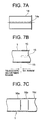
- FIGS. 7A - 7C show a third embodiment.
- FIG. 7A is a semi-sectional view of a sleeve.
- FIG. 7B is a partial sectional view showing a modified example of the inner column.
- FIG. 7C is a partial sectional view of a further modified example of the inner column.
- Each of these sleeves is inserted in between the outer column 2 and the inner column 1 of the steering column apparatus as shown in, e.g., FIG. 5.
- a sleeve 14, of which an inner surface is subjected to the low-friction material treatment is fitted into portions corresponding to the fitting portions of the two columns along the inner surface of the outer column 2 of the steering column apparatus shown in FIG. 5.
- the low-friction material treatment is one of the baking of molybdenum disulfide, the baking of fluororesin, the baking of the mixture of molybdenum disulfide and fluororesin, the coating of a ceramic, the metal soap treatment, the low-friction plating treatment and the coating of the lubricating agent such as grease, etc. but is not limited to these treatments.
- a single slit 14a is formed in a circumferential area, thereby facilitating the low-friction material treatment on the inner surface. This is because rounding work can be carried out after the low-friction material treatment. Moreover, the low-friction treatment may be effected also on the outer periphery of the inner column.
- FIG. 7B shows an example in which a plurality of protruded streaks 15 are formed in the peripheral direction of the inner column 1.
- the protruded streaks 15 on the inner column 1 are press-fitted into the outer column 2, thereby generating the collapse load.
- the impact energy is thus absorbed.
- the low-friction material is coated over at least one of the inner column and the outer column.
- An area formed with the protruded streaks on the inner column 1 serves as the energy absorption (EA) range, while the left side area of the inner column 1 from the protruded streak 15 in FIG. 7B serves as the telescopic adjustment range.
- EA energy absorption
- FIG. 7C shows an example in which the inner column 1 is formed so that its diameter gradually becomes larger in the sequence of a small-diameter portion 16a, an intermediate-diameter portion 16b and a large-diameter portion 16c.
- the small-diameter portion 16a, the intermediate-diameter portion 16b and the large-diameter portion 16c of the inner column 1 are sequentially press-fitted into the outer column 2, thereby generating the collapse load.
- the impact energy is thus absorbed.
- the inner column 1 may be formed in an elliptical shape suited for changing its diameter.
- the low friction material is coated over at least one of the inner column and the outer column.
- the impact absorption system may be the system for press-fitting into the outer column 2, or may be the system for expanding the telescopic adjustment groove 13 as in the first and second embodiments, or may also be a combination of these systems.
- Other systems are available without being limited to those systems on condition that the energy absorption types be those utilizing the relative movement of the inner column to the outer column.
- FIG. 8 is a side view of an impact absorption type steering column apparatus of the tilt/telescopic type according to a fourth embodiment of the present invention.
- FIG. 2A is a sectional view taken along the line A-A in FIG. 8.
- the tilt/telescopic adjustment mechanism is the same as that in the second embodiment.
- FIG. 9 is a side view of the steering column apparatus shown in FIG. 8, showing a shortest telescopic adjustment state.
- FIG. 10 is a side view of the steering column apparatus shown in FIG. 8, showing a state in which the absorption of the impact generated upon the secondary collision is terminated.
- a metallic ring 20 formed of iron, etc. is press-fitted or otherwise into a predetermined position of an outer peripheral surface of the inner column 1.
- An annular damper 21 formed of a rubber or a synthetic resin is provided integrally with the metallic ring 20 on the side of the outer column 2.
- the metallic ring 20 and the damper 21 when adjusted to the shortest telescopic adjustment state, act as a stopper for regulating the telescopic slide by abutting on the outer column 2. Moreover, on this occasion, the damper 21 prevents abutting noises caused by abutting on the outer column 2 and also restrains an impact thereof.
- the low-friction material treatment is effected on one or both of the slide surfaces, especially at least on the collapse slide surface at the fitting portions of the two columns 1, 2.
- the low-friction material treatment may also be effected on the slide-abutting surface in the energy absorption range.
- the low-friction material treatment is one of the baking of molybdenum disulfide, the baking of fluororesin, the baking of the mixture of molybdenum disulfide and fluororesin, the coating of a ceramic, the metal soap treatment, the low-friction plating treatment and the coating of the lubricating agent such as grease, etc. but is not limited to these treatments.
- the low-friction material treatment is effected on one or both of the slide surfaces of the fitting portions of the two columns 1, 2, and hence the slide load of the inner column 1 can be reduced by decreasing the coefficient of the friction on the slide surfaces of the fitting portions of the two columns 1, 2. Accordingly, if the fitting length between the two columns 1, 2 is comparatively short, or even if the fitting angle of the steering wheel is large, the smooth start of the movement of the inner column 1 towards the front side of the automotive vehicle can be attained.
- the subsequent collapsing can be smoothly performed, thereby facilitating the control of the absorption of the impact energy.
- none of the blocking load affects the two columns, thereby enabling the collapsing to be smoothly done.
- the low-friction material treatment is effected on one or both of the slide surfaces of the fitting portions of the two columns 1, 2, and therefore the operating force for the telescopic adjustment can be reduced by decreasing the coefficient of friction on the slide surfaces of the fitting portions of the two columns 1, 2, whereby the operation for the telescopic adjustment can be smoothly conducted.
- FIG. 11 is a side view of an impact absorption type steering column apparatus of the tilt/telescopic type according to a fifth embodiment of the present invention.
- the tilt/telescopic adjustment mechanism is the same as that in the second embodiment.
- FIG. 6 is a sectional view taken along the line B-B in FIG. 11.
- a metallic ring 20 formed of iron, etc. is press-fitted or otherwise into a predetermined position on the inner column 1.
- a damper 21 formed of a rubber or a synthetic resin is provided integrally with the metallic ring 20 on the side of the outer column 2.
- the metallic ring 20 and the damper 21 impinge on the rear end of the outer column 2. Thereafter, the inner column 1 further moves towards the front side of the automotive vehicle. On this occasion, the metallic ring 20 frictionally slides on the outer peripheral surface of the inner column 1 moving towards the front side of the automotive vehicle while being engaged and stopped with the rear end of the outer column 2, thereby generating the collapse load. The impact energy is thus absorbed.
- the outer jacket 102 integral with the outer column 2 is formed integrally with a housing of the electric power assist (Electric Power Steering (EPS)) mechanism.
- EPS Electric Power Steering
- the low-friction material treatment is effected on one or both of the slide surfaces of the fitting portions of the two columns 1, 2.
- the low-friction material treatment is as described above and effected in at least the telescopic slide-abutting range anterior to the ring and may also be effected posterior to the ring.
- the low-friction material treatment is effected on one or both of the slide surfaces of the fitting portions of the two columns 1, 2, and hence the slide load of the inner column 1 can be reduced by decreasing the coefficient of the friction on the slide surfaces of the fitting portions of the two columns 1, 2. Accordingly, if the fitting length between the two columns 1, 2 is comparatively short, or even if the fitting angle of the steering wheel is large, the smooth start of the movement of the inner column 1 towards the front side of the automotive vehicle can be attained. As a result, the subsequent collapsing can be smoothly performed, thereby facilitating the control of the absorption of the impact energy.
- the telescopic adjustment system if handled with one hand when performing the operation for the telescopic adjustment, the movement of the inner column through within the outer column gets unsmoothed (blocked), resulting possibly in the rise in the telescopic operating force.
- the low-friction material treatment is effected on one or both of the slide surfaces of the fitting portions of the two columns 1, 2, and therefore the telescopic operating force can be reduced by decreasing the coefficient of friction on the slide surfaces of the fitting portions of the two columns 1, 2, whereby the telescopic operation can be smoothly conducted.
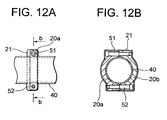
- FIG. 12A is a side view of an impact absorption type steering column apparatus of the tilt/telescopic type according to a sixth embodiment of the present invention.
- FIG. 12B is a sectional view taken along the line b-b in FIG. 12A.
- the metallic ring 20 is fitted on an outer peripheral surface of an inner column 40 subjected to the low-friction material treatment described above.
- the metallic ring 20 is constructed of a pair of half-ring segments 20a, 20b into which the ring 20 is segmented by half.
- the pair of half-ring segments 20a, 20b are fastened at their upper and lower ends by a pair of bolts 51, 52.
- a damper 21 formed of a synthetic resin is covered over the pair of half-ring segments 20a, 20b.
- a gap between the two pieces of half-ring segments 20a, 20b is changed by varying the fastening force of the pair of bolts 51, 52, whereby the fitting state (fastening state) of the metallic ring 20 can be adjusted and the collapse load can be set and adjusted much easier than in the embodiments discussed above.
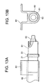
- FIG. 13A is a side view of an impact absorption type steering column apparatus of a non-telescopic type according to a seventh embodiment of the present invention.
- FIG. 13B is a rear view (showing the front side as viewed from the rear side of the automotive vehicle) of the steering column apparatus shown in FIG. 13A.
- the impact absorption type steering column apparatus in the seventh embodiment comes under a non-telescopic adjustment system incapable of making the telescopic adjustment, wherein an inner column 61 is so press-fitted into an outer column 62 formed integrally with a car body sided bracket 60 as not to slide thereon at a normal time, and a steering shaft 63 is rotatably supported within the two columns 61, 62. If the secondary collision happens, however, a contrivance is that the inner column 61 becomes movable along the outer column 62 towards the front side of the automotive vehicle.
- the metallic ring 20 formed of iron, etc. is press-fitted or otherwise into a predetermined position on the inner column 61.
- the damper 21 formed of a rubber or a synthetic resin is provided on the metallic ring 20 on the side of an outer column 62.
- the metallic ring 20 and the damper 21 impinge on the rear end of the outer column 62. Thereafter, the inner column 61 further moves towards the front side of the automotive vehicle. On this occasion, the metallic ring 20 frictionally slides on the outer peripheral surface of the inner column 61 moving towards the front side of the automotive vehicle while engaging with the rear side end of the outer column 62, thereby generating the collapse load. The impact energy is thus absorbed.
- the low-friction material treatment is effected on one or both of the slide surfaces of the fitting portions of the two columns 61, 62.
- the low-friction material treatment is as described above.
- the low-friction material treatment is effected on the press-fitting portions of the two columns 61, 62 or on the energy absorbing portion.
- the low-friction material treatment is effected on one or both of the slide surfaces of the fitting portions of the two columns 61, 62, and hence the slide load of the inner column 61 can be reduced by decreasing the coefficient of the friction on the slide surfaces of the fitting portions of the two columns 61, 62. Accordingly, if the fitting length between the two columns 61, 62 is comparatively short, or even if the fitting angle of the steering wheel is large, the smooth start of the movement of the inner column 61 towards the front side of the automotive vehicle can be attained. As a result, the subsequent collapsing can be smoothly performed, thereby facilitating the control of the absorption of the impact energy.
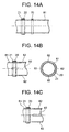
- FIGS. 14A - 14C are semi-sectional views of the steering column in an eighth embodiment of the present invention.
- FIG. 14A is the semi-sectional view showing a first example thereof.
- FIG. 14B shows a semi-sectional view and a rear view illustrating a second example thereof.
- FIG. 14C is the semi-sectional view showing a third example thereof.
- the eighth embodiment can be applied to the fourth through seventh embodiments discussed above.
- FIGS. 15A - 15D are semi-sectional views of the steering column in the eighth embodiment of the present invention.
- FIG. 15A is the semi-sectional view showing a fourth example thereof.
- FIG. 15B is a semi-sectional view showing a fifth example thereof.
- FIG. 15C is the semi-sectional view showing a sixth example thereof.
- FIG. 15D is the semi-sectional view showing a seventh example thereof.
- FIGS. 14A - 14C and 15A - 15D the right side corresponds to the rear side of the automotive vehicle, while the left side corresponds to the front side of the automotive vehicle.
- the configurations on the front and rear sides of the automotive vehicle are the same as the configurations of the front and rear sides of the ring 20 and of the damper 21 in FIG. 11.
- the ring 20 impinges on the outer jacket, subsequently the collapsing progresses to such an extent that the outer jacket impinges on the ring 70, thereby absorbing the energy.
- another metallic ring 70 is provided in a different position on the steering column 81 in the axial directions.
- the second example in FIG. 14B is that the steering column 81 is formed with four lines of protruded streaks 82 spaced equally in the peripheral direction. Each of the protruded streaks 82 extends in the axial directions.
- the metallic ring 20 and the damper 21 are press-fitted onto the outer peripheral portions of these protruded streaks 82.
- the protruded streaks may be a plastically deformable member as shown in the Figure and may also be formed by cut-raising.
- the third example in FIG. 14C is that the same metallic ring 20 and damper 21 as those in the fourth embodiment are fitted onto the portions of the protruded streaks 82 on the front side of the automotive vehicle. With this contrivance, resistance caused by the frictional slide is increased stepwise, thereby augmenting the collapse load.
- the steering column 81 is constructed of a small-diameter portion 81a, an intermediate-diameter portion 81b and a large-diameter portion 81c.
- the same metallic ring 20 and damper 21 as those in the fourth embodiment are fitted onto the small-diameter portion 81a. Owing to this contrivance, the resistance caused by the frictional slide is increased at three stages, thereby further augmenting the collapse load. Moreover, the collapsing characteristic can be changed as intended in a way that properly changes lengths of the large-, intermediate- and small-diameter portions.
- the fifth example in FIG. 15B is such that a tapered portion 81d is formed between the small-diameter portion 81a and the large-diameter portion 81c, and the metallic ring 20 and the damper 21 are fitted onto the small-diameter portion 81a. With this contrivance, the resistance caused by the frictional slide is gradually increased, thereby further augmenting the collapse load.
- the sixth example in FIG. 15C is that the steering column 81 has the metallic ring 20 that is made thin in its wall thickness on the rear side of the automotive vehicle, and is formed with a resistance-escape hole 83. Owing to this contrivance, the resistance caused by the frictional slide is reduced, thus attaining a scheme of decreasing the collapse load.
- the steering column 81 has the metallic ring 20 that is made thin in its wall thickness of a major-diametrical portion thereof on the rear side of the automotive vehicle. With this contrivance, the resistance caused by the frictional slide is reduced, thus attaining a scheme of decreasing the collapse load.
- the present invention can be modified in a variety of forms without being limited to the embodiments discussed above.
- the present invention can be applied to an electric power steering system and is highly effective in a column type electric power steering particularly because of difficulty of setting a sufficient amount of collapsing.
- the present invention is also applicable to a tilt type and a telescopic type.
- the low-friction material treatment is effected on one or both of the slide surfaces of the fitting portions of the telescopic adjustment portions between the two columns. Then, if the steering column apparatus is one of the non-telescopic adjustment type, the low-friction material treatment is effected on the press-fitting portions of the two columns, and it is therefore possible to reduce the slide load of the upper column by reducing the coefficient of friction on the slide surfaces of the fitting portions of the two columns. Accordingly, if the fitting length between the two columns is comparatively short, or even if the fitting angle of the steering wheel is large, the smooth start of the movement of the upper column towards the front side of the automotive vehicle can be attained.
- the subsequent collapsing can be smoothly performed, thereby facilitating the control of the absorption of the impact energy.
- none of the blocking load affects the two columns, thereby enabling the collapsing to be smoothly done.
- the low-friction material treatment is effected on one or both of the slide surfaces of the fitting portions of the two columns, and therefore the telescopic operating force can be reduced by decreasing the coefficient of friction on the slide surfaces of the fitting portions of the two columns, whereby the telescopic operation can be smoothly conducted.
Landscapes
- Engineering & Computer Science (AREA)
- Chemical & Material Sciences (AREA)
- Combustion & Propulsion (AREA)
- Transportation (AREA)
- Mechanical Engineering (AREA)
- Steering Controls (AREA)
Abstract
Description
Claims (5)
- In an impact absorbing type steering column apparatus for an automotive vehicle in which an upper column is fitted to a lower column fixed to a car body so as to absorb an impact energy upon a secondary collision while moving said upper column towards a front side of the automotive vehicle,
an improvement characterized in that a low-friction material treatment is effected on one or both of slide surfaces of fitting portions of said two columns. - An impact absorbing type steering column apparatus for an automotive vehicle according to claim 1, wherein said steering column apparatus is of an electric power steering type of a column assist type.
- An impact absorbing type steering column apparatus for an automotive vehicle according to claim 1, wherein said steering column apparatus is of an electric power steering type of a column assist type, and is capable of making a telescopic adjustment.
- In an impact absorbing type steering column apparatus for an automotive vehicle in which an upper column is fitted to a lower column fixed to a car body so as to absorb an impact energy upon a secondary collision while moving said upper column towards a front side of the automotive vehicle,
an improvement characterized in that a sleeve subjected to a low-friction material treatment is interposed between fitting portions of said two columns. - An impact absorbing type steering column apparatus for an automotive vehicle according to any one of claims 1 through 4, wherein the low-friction material treatment is one of baking of molybdenum disulfide, baking of fluororesin, baking of a mixture of molybdenum disulfide and fluororesin, coating of a ceramic, a metal soap treatment, a low-friction plating treatment and coating of a lubricating agent.
Applications Claiming Priority (3)
| Application Number | Priority Date | Filing Date | Title |
|---|---|---|---|
| JP2002179131 | 2002-06-19 | ||
| JP2002179131 | 2002-06-19 | ||
| PCT/JP2003/007791 WO2004000627A1 (en) | 2002-06-19 | 2003-06-19 | Shock absorbing steering column unit for vehicle |
Publications (3)
| Publication Number | Publication Date |
|---|---|
| EP1516798A1 true EP1516798A1 (en) | 2005-03-23 |
| EP1516798A4 EP1516798A4 (en) | 2006-08-02 |
| EP1516798B1 EP1516798B1 (en) | 2008-10-01 |
Family
ID=29996557
Family Applications (1)
| Application Number | Title | Priority Date | Filing Date |
|---|---|---|---|
| EP03760906A Expired - Lifetime EP1516798B1 (en) | 2002-06-19 | 2003-06-19 | Shock absorbing steering column unit for vehicle |
Country Status (6)
| Country | Link |
|---|---|
| US (1) | US20050173914A1 (en) |
| EP (1) | EP1516798B1 (en) |
| JP (1) | JPWO2004000627A1 (en) |
| CN (1) | CN100526143C (en) |
| DE (1) | DE60323837D1 (en) |
| WO (1) | WO2004000627A1 (en) |
Cited By (1)
| Publication number | Priority date | Publication date | Assignee | Title |
|---|---|---|---|---|
| EP3360756A1 (en) * | 2017-02-13 | 2018-08-15 | JTEKT Corporation | Steering system |
Families Citing this family (33)
| Publication number | Priority date | Publication date | Assignee | Title |
|---|---|---|---|---|
| JP4147579B2 (en) * | 2002-01-17 | 2008-09-10 | 日本精工株式会社 | Steering device |
| CN100369779C (en) * | 2002-07-08 | 2008-02-20 | 日本精工株式会社 | Electric Steering |
| JP2005280678A (en) * | 2004-03-04 | 2005-10-13 | Nsk Ltd | Steering device |
| JP4548832B2 (en) * | 2005-01-12 | 2010-09-22 | 日新製鋼株式会社 | Automotive steering structure |
| JP4379463B2 (en) * | 2006-10-31 | 2009-12-09 | トヨタ自動車株式会社 | Knee airbag device with column |
| JP2009119999A (en) * | 2007-11-14 | 2009-06-04 | Toyota Motor Corp | Vehicle steering column device |
| US7703804B2 (en) * | 2007-12-27 | 2010-04-27 | Gm Global Technology Operations, Inc. | Telescopically adjustable steering column assembly including an adjustment stop having minimal effect on impact loads |
| KR101268274B1 (en) * | 2009-06-30 | 2013-05-31 | 주식회사 만도 | Steering Column for Vehicle |
| DE102010044495B4 (en) * | 2009-09-07 | 2014-07-03 | Mando Corporation | Steering column for a vehicle |
| DE102009055973B3 (en) * | 2009-11-27 | 2011-06-16 | Thyssenkrupp Presta Ag | Steering column for a motor vehicle |
| JP5077420B2 (en) * | 2010-12-03 | 2012-11-21 | 日本精工株式会社 | Shock absorption steering column device and electric power steering device |
| CN105128926B (en) * | 2011-02-02 | 2017-12-19 | 日本精工株式会社 | Electric type power steering device pole unit |
| US20130133461A1 (en) * | 2011-11-30 | 2013-05-30 | Nexteer (Beijing) Technology Co., Ltd. | Energy absorbing steering column assembly |
| JP5999767B2 (en) * | 2012-12-27 | 2016-09-28 | 株式会社ジェイテクト | Steering device |
| CN105473418B (en) * | 2013-10-30 | 2017-08-08 | 日本精工株式会社 | Steering device |
| CN103818428B (en) * | 2014-02-27 | 2016-06-08 | 长城汽车股份有限公司 | A kind of steering column crumple energy absorption device and column assy |
| WO2015190301A1 (en) * | 2014-06-13 | 2015-12-17 | 日本精工株式会社 | Steering device |
| CN106458247B (en) | 2014-06-13 | 2018-05-25 | 日本精工株式会社 | Steering device |
| JP6417796B2 (en) * | 2014-09-02 | 2018-11-07 | アイシン精機株式会社 | Steering device |
| CN106715240B (en) | 2014-09-16 | 2018-08-28 | 日本精工株式会社 | Transfer |
| JP6429077B2 (en) * | 2015-01-26 | 2018-11-28 | 株式会社ジェイテクト | Steering device |
| DE102015002889B3 (en) * | 2015-03-09 | 2016-05-12 | Thyssenkrupp Ag | Adjustable steering column with improved rigidity |
| US9789897B2 (en) * | 2015-08-11 | 2017-10-17 | Yamada Manufacturing Co., Ltd. | Steering apparatus |
| DE102015216326B4 (en) * | 2015-08-26 | 2016-09-08 | Thyssenkrupp Ag | Motor-adjustable steering column for a motor vehicle |
| JP6627427B2 (en) * | 2015-10-30 | 2020-01-08 | 日本精工株式会社 | Steering device |
| CN107428360B (en) | 2016-03-15 | 2018-10-26 | 日本精工株式会社 | Steering device |
| GB201604974D0 (en) * | 2016-03-23 | 2016-05-04 | Trw Das A S | A steering column assembly |
| DE102016205378B3 (en) * | 2016-03-31 | 2017-05-11 | Thyssenkrupp Ag | Steering column for a motor vehicle |
| KR20180022289A (en) * | 2016-08-24 | 2018-03-06 | 현대자동차주식회사 | Telescopic latch appratus of steering column for vehicle |
| JP6753737B2 (en) * | 2016-08-31 | 2020-09-09 | 株式会社山田製作所 | Steering device |
| CN110091909B (en) * | 2018-01-31 | 2020-10-02 | 长城汽车股份有限公司 | Steering device for vehicle and vehicle |
| DE102018211046B3 (en) * | 2018-07-04 | 2019-08-29 | Thyssenkrupp Ag | Method for adjusting the actuating force for fixing an adjustable steering column |
| US11565640B2 (en) * | 2019-12-05 | 2023-01-31 | Karma Automotive Llc | Support bracket |
Family Cites Families (13)
| Publication number | Priority date | Publication date | Assignee | Title |
|---|---|---|---|---|
| JPS5751574A (en) * | 1980-09-10 | 1982-03-26 | Fuji Kiko Co Ltd | Shock energy absorbing steering device |
| JPH01172965A (en) | 1987-12-28 | 1989-07-07 | Fuji Electric Co Ltd | Electrophotographic sensitive body |
| JPH01172965U (en) * | 1988-05-18 | 1989-12-07 | ||
| JP2983130B2 (en) | 1993-09-07 | 1999-11-29 | 光洋精工株式会社 | Impact absorbing steering column and method of manufacturing the same |
| US5417614A (en) * | 1994-03-14 | 1995-05-23 | General Motors Corporation | Variable length shaft assembly |
| US5590565A (en) * | 1995-02-08 | 1997-01-07 | General Motors Corporation | Motor vehicle steering column |
| JPH0995245A (en) | 1995-09-28 | 1997-04-08 | Koyo Seiko Co Ltd | Impact absorption type steering column |
| JP3004590B2 (en) * | 1996-08-02 | 2000-01-31 | 株式会社山田製作所 | Steering shaft |
| JP2000127991A (en) * | 1998-10-30 | 2000-05-09 | Nsk Ltd | Shock absorbing steering device and automobile |
| JP3853150B2 (en) * | 1999-12-02 | 2006-12-06 | 株式会社ジェイテクト | Telescopic shaft |
| JP2001208089A (en) * | 2000-01-27 | 2001-08-03 | Nsk Ltd | Connecting structure of telescopic shaft |
| JP3431886B2 (en) * | 2000-07-07 | 2003-07-28 | 株式会社山田製作所 | Steering position adjustment device |
| US7047836B2 (en) * | 2002-02-01 | 2006-05-23 | Trw Inc. | Surface treatment for a locking mechanism |
-
2003
- 2003-06-19 US US10/517,259 patent/US20050173914A1/en not_active Abandoned
- 2003-06-19 CN CNB038143658A patent/CN100526143C/en not_active Expired - Fee Related
- 2003-06-19 DE DE60323837T patent/DE60323837D1/en not_active Expired - Lifetime
- 2003-06-19 WO PCT/JP2003/007791 patent/WO2004000627A1/en not_active Ceased
- 2003-06-19 EP EP03760906A patent/EP1516798B1/en not_active Expired - Lifetime
- 2003-06-19 JP JP2004515517A patent/JPWO2004000627A1/en active Pending
Cited By (2)
| Publication number | Priority date | Publication date | Assignee | Title |
|---|---|---|---|---|
| EP3360756A1 (en) * | 2017-02-13 | 2018-08-15 | JTEKT Corporation | Steering system |
| US10479395B2 (en) | 2017-02-13 | 2019-11-19 | Jtekt Corporation | Steering system |
Also Published As
| Publication number | Publication date |
|---|---|
| EP1516798A4 (en) | 2006-08-02 |
| JPWO2004000627A1 (en) | 2005-10-20 |
| WO2004000627A1 (en) | 2003-12-31 |
| CN100526143C (en) | 2009-08-12 |
| EP1516798B1 (en) | 2008-10-01 |
| CN1662411A (en) | 2005-08-31 |
| US20050173914A1 (en) | 2005-08-11 |
| DE60323837D1 (en) | 2008-11-13 |
Similar Documents
| Publication | Publication Date | Title |
|---|---|---|
| EP1516798B1 (en) | Shock absorbing steering column unit for vehicle | |
| US7445241B2 (en) | Vehicle impact absorption type steering column device | |
| US7413222B2 (en) | Position adjustment type steering column device for vehicles | |
| US5718131A (en) | Steering column locking assembly | |
| EP3357789B1 (en) | Steering system | |
| EP2923922B1 (en) | Steering Device | |
| US20070137377A1 (en) | Collapsible steering column device having telescopic mechanism | |
| JP7424306B2 (en) | steering column device | |
| EP1156229A1 (en) | Connection structure of extensible shaft | |
| US9669781B2 (en) | Steering apparatus | |
| JP7310828B2 (en) | steering column device | |
| CN111376967A (en) | Steering system | |
| US20180327018A1 (en) | Vertical position adjustment device for steering wheel | |
| CN114616163B (en) | Outer tube with hole cover | |
| DE102022208251A1 (en) | Anti-rattle caliper assembly | |
| JPH0527338Y2 (en) | ||
| GB2267873A (en) | Collapsible steering column for a vehicle | |
| JPH078157U (en) | Steering wheel position adjustment device | |
| US20210362769A1 (en) | Steering Column and Steering Device | |
| GB2557256A (en) | A collapsible non adjustable steering column assembly | |
| DE19604194A1 (en) | Hub for two=wheeled vehicle | |
| JP2013169800A (en) | Position adjusting type steering column device for vehicle | |
| JPH04137968U (en) | vehicle steering device | |
| JPH0580954U (en) | Telescopic steering device | |
| JPH0522255U (en) | Electric telescopic steering device |
Legal Events
| Date | Code | Title | Description |
|---|---|---|---|
| PUAI | Public reference made under article 153(3) epc to a published international application that has entered the european phase |
Free format text: ORIGINAL CODE: 0009012 |
|
| 17P | Request for examination filed |
Effective date: 20050113 |
|
| AK | Designated contracting states |
Kind code of ref document: A1 Designated state(s): AT BE BG CH CY CZ DE DK EE ES FI FR GB GR HU IE IT LI LU MC NL PT RO SE SI SK TR |
|
| RBV | Designated contracting states (corrected) |
Designated state(s): DE FR GB |
|
| A4 | Supplementary search report drawn up and despatched |
Effective date: 20060629 |
|
| RIC1 | Information provided on ipc code assigned before grant |
Ipc: B62D 5/04 20060101ALI20060623BHEP Ipc: B62D 1/181 20060101ALI20060623BHEP Ipc: B60R 21/05 20060101ALI20060623BHEP Ipc: B62D 1/19 20060101AFI20040114BHEP |
|
| 17Q | First examination report despatched |
Effective date: 20070202 |
|
| GRAP | Despatch of communication of intention to grant a patent |
Free format text: ORIGINAL CODE: EPIDOSNIGR1 |
|
| GRAS | Grant fee paid |
Free format text: ORIGINAL CODE: EPIDOSNIGR3 |
|
| GRAA | (expected) grant |
Free format text: ORIGINAL CODE: 0009210 |
|
| AK | Designated contracting states |
Kind code of ref document: B1 Designated state(s): DE FR GB |
|
| REG | Reference to a national code |
Ref country code: GB Ref legal event code: FG4D |
|
| REF | Corresponds to: |
Ref document number: 60323837 Country of ref document: DE Date of ref document: 20081113 Kind code of ref document: P |
|
| PLBE | No opposition filed within time limit |
Free format text: ORIGINAL CODE: 0009261 |
|
| STAA | Information on the status of an ep patent application or granted ep patent |
Free format text: STATUS: NO OPPOSITION FILED WITHIN TIME LIMIT |
|
| 26N | No opposition filed |
Effective date: 20090702 |
|
| PGFP | Annual fee paid to national office [announced via postgrant information from national office to epo] |
Ref country code: GB Payment date: 20090617 Year of fee payment: 7 |
|
| GBPC | Gb: european patent ceased through non-payment of renewal fee |
Effective date: 20100619 |
|
| REG | Reference to a national code |
Ref country code: FR Ref legal event code: ST Effective date: 20110228 |
|
| PG25 | Lapsed in a contracting state [announced via postgrant information from national office to epo] |
Ref country code: FR Free format text: LAPSE BECAUSE OF NON-PAYMENT OF DUE FEES Effective date: 20100630 |
|
| PG25 | Lapsed in a contracting state [announced via postgrant information from national office to epo] |
Ref country code: GB Free format text: LAPSE BECAUSE OF NON-PAYMENT OF DUE FEES Effective date: 20100619 |
|
| PGFP | Annual fee paid to national office [announced via postgrant information from national office to epo] |
Ref country code: FR Payment date: 20090611 Year of fee payment: 7 |
|
| PGFP | Annual fee paid to national office [announced via postgrant information from national office to epo] |
Ref country code: DE Payment date: 20130612 Year of fee payment: 11 |
|
| REG | Reference to a national code |
Ref country code: DE Ref legal event code: R119 Ref document number: 60323837 Country of ref document: DE |
|
| REG | Reference to a national code |
Ref country code: DE Ref legal event code: R119 Ref document number: 60323837 Country of ref document: DE Effective date: 20150101 |
|
| PG25 | Lapsed in a contracting state [announced via postgrant information from national office to epo] |
Ref country code: DE Free format text: LAPSE BECAUSE OF NON-PAYMENT OF DUE FEES Effective date: 20150101 |