EP1516672B1 - Method and apparatus for separating of organic from inorganic material - Google Patents
Method and apparatus for separating of organic from inorganic material Download PDFInfo
- Publication number
- EP1516672B1 EP1516672B1 EP04021875A EP04021875A EP1516672B1 EP 1516672 B1 EP1516672 B1 EP 1516672B1 EP 04021875 A EP04021875 A EP 04021875A EP 04021875 A EP04021875 A EP 04021875A EP 1516672 B1 EP1516672 B1 EP 1516672B1
- Authority
- EP
- European Patent Office
- Prior art keywords
- container
- inorganic material
- organic material
- cleaning water
- fluidized layer
- Prior art date
- Legal status (The legal status is an assumption and is not a legal conclusion. Google has not performed a legal analysis and makes no representation as to the accuracy of the status listed.)
- Expired - Lifetime
Links
- 239000011147 inorganic material Substances 0.000 title claims abstract description 50
- 229910010272 inorganic material Inorganic materials 0.000 title claims abstract description 47
- 238000000034 method Methods 0.000 title claims description 7
- XLYOFNOQVPJJNP-UHFFFAOYSA-N water Substances O XLYOFNOQVPJJNP-UHFFFAOYSA-N 0.000 claims abstract description 68
- 239000011368 organic material Substances 0.000 claims abstract description 44
- 239000004576 sand Substances 0.000 claims description 58
- 230000033001 locomotion Effects 0.000 claims description 23
- 238000004140 cleaning Methods 0.000 claims description 16
- 239000000203 mixture Substances 0.000 claims description 11
- 238000003756 stirring Methods 0.000 claims description 9
- 239000000523 sample Substances 0.000 claims description 8
- 238000000926 separation method Methods 0.000 claims description 6
- 239000010865 sewage Substances 0.000 claims description 4
- 238000007599 discharging Methods 0.000 claims 4
- 230000001419 dependent effect Effects 0.000 claims 1
- 238000005406 washing Methods 0.000 abstract description 28
- 239000010410 layer Substances 0.000 description 35
- 230000001681 protective effect Effects 0.000 description 23
- 239000000463 material Substances 0.000 description 7
- 230000000694 effects Effects 0.000 description 4
- 230000007423 decrease Effects 0.000 description 3
- 239000013505 freshwater Substances 0.000 description 3
- 239000007788 liquid Substances 0.000 description 3
- 239000000126 substance Substances 0.000 description 3
- 241001417527 Pempheridae Species 0.000 description 2
- 230000005587 bubbling Effects 0.000 description 2
- 230000005465 channeling Effects 0.000 description 2
- 238000000605 extraction Methods 0.000 description 2
- 230000003993 interaction Effects 0.000 description 2
- 238000012423 maintenance Methods 0.000 description 2
- 238000004519 manufacturing process Methods 0.000 description 2
- 239000012044 organic layer Substances 0.000 description 2
- 230000000630 rising effect Effects 0.000 description 2
- 239000007787 solid Substances 0.000 description 2
- 235000010678 Paulownia tomentosa Nutrition 0.000 description 1
- 240000002834 Paulownia tomentosa Species 0.000 description 1
- 230000005540 biological transmission Effects 0.000 description 1
- 230000015572 biosynthetic process Effects 0.000 description 1
- 238000004891 communication Methods 0.000 description 1
- 239000000470 constituent Substances 0.000 description 1
- 238000011109 contamination Methods 0.000 description 1
- 230000001276 controlling effect Effects 0.000 description 1
- 230000003247 decreasing effect Effects 0.000 description 1
- 230000008021 deposition Effects 0.000 description 1
- 238000009826 distribution Methods 0.000 description 1
- 238000011086 high cleaning Methods 0.000 description 1
- 229910052500 inorganic mineral Inorganic materials 0.000 description 1
- 239000011707 mineral Substances 0.000 description 1
- 150000002894 organic compounds Chemical class 0.000 description 1
- 239000005416 organic matter Substances 0.000 description 1
- 239000002245 particle Substances 0.000 description 1
- 230000001105 regulatory effect Effects 0.000 description 1
- 238000011144 upstream manufacturing Methods 0.000 description 1
- 239000002351 wastewater Substances 0.000 description 1
Images

Classifications
-
- B—PERFORMING OPERATIONS; TRANSPORTING
- B01—PHYSICAL OR CHEMICAL PROCESSES OR APPARATUS IN GENERAL
- B01D—SEPARATION
- B01D21/00—Separation of suspended solid particles from liquids by sedimentation
- B01D21/24—Feed or discharge mechanisms for settling tanks
- B01D21/245—Discharge mechanisms for the sediments
- B01D21/2461—Positive-displacement pumps; Screw feeders; Trough conveyors
-
- B—PERFORMING OPERATIONS; TRANSPORTING
- B03—SEPARATION OF SOLID MATERIALS USING LIQUIDS OR USING PNEUMATIC TABLES OR JIGS; MAGNETIC OR ELECTROSTATIC SEPARATION OF SOLID MATERIALS FROM SOLID MATERIALS OR FLUIDS; SEPARATION BY HIGH-VOLTAGE ELECTRIC FIELDS
- B03B—SEPARATING SOLID MATERIALS USING LIQUIDS OR USING PNEUMATIC TABLES OR JIGS
- B03B13/00—Control arrangements specially adapted for wet-separating apparatus or for dressing plant, using physical effects
-
- B—PERFORMING OPERATIONS; TRANSPORTING
- B03—SEPARATION OF SOLID MATERIALS USING LIQUIDS OR USING PNEUMATIC TABLES OR JIGS; MAGNETIC OR ELECTROSTATIC SEPARATION OF SOLID MATERIALS FROM SOLID MATERIALS OR FLUIDS; SEPARATION BY HIGH-VOLTAGE ELECTRIC FIELDS
- B03B—SEPARATING SOLID MATERIALS USING LIQUIDS OR USING PNEUMATIC TABLES OR JIGS
- B03B5/00—Washing granular, powdered or lumpy materials; Wet separating
- B03B5/62—Washing granular, powdered or lumpy materials; Wet separating by hydraulic classifiers, e.g. of launder, tank, spiral or helical chute concentrator type
- B03B5/623—Upward current classifiers
Definitions
- the invention relates to a method and a device for separating organic material from inorganic material, in particular from organic polluted sand of sewage treatment plants, with a container having in its upper region a charging device for the introduction of contaminated inorganic material into the container, with a In the lower portion of the container arranged discharge means for the separated inorganic material, a means for removing the organic material and a supply means for washing water in the lower region of the container, wherein above the supply means for washing water in the container, the separation of the organic material from the inorganic material in one fluidized layer takes place.
- the container of the device can be created in particular in round design, but also with polygonal cross-section. It has a vertical axis and can be composed of cylindrical and conical sections.
- the device is used for washing the organically polluted sand.
- the inorganic material ie the sand
- the separated organic material can be withdrawn together with the wash water, but alternatively also via a separate extraction device.
- the material which is taken from the sand trap of sewage treatment plants or in the sewer cleaning from the sewer system, but also street sweeper, as recorded by sweepers, contains in addition to the inorganic material in the form of sand, stones and the like often considerable amounts of organic material , To the inorganic material In order to be able to feed or otherwise reuse a landfill, it must to a certain extent be freed from the organic material in order to be able to carry out a cost-effective disposal.
- a device of the type described above is known from DE 44 15 647 C2 or even the EP 0 707 520 B1 known.
- the device has a container with a vertical axis.
- the container has a section extending from bottom to top in sections.
- a charging device for the introduction of contaminated inorganic material is provided in the container.
- a discharge device for the separated purified inorganic material which consists of an obliquely upward guided screw conveyor.
- a supply device for washing water In the lower region of the container, above the discharge device for the separated inorganic material, a supply device for washing water is provided, which has a perforated bottom.
- the perforated bottom has a plurality of apertures, nozzles or the like arranged distributed over the cross section, so that with its help a flow which is distributed over the cross section and is directed upward is produced.
- the washing water is supplied in such an amount per unit time and dispensed distributed through the openings of the perforated bottom that a fluidized layer is formed above the perforated bottom, ie a fluidized bed through which the organically contaminated inorganic material is placed in the typical fluidized bed motion state in which the grains of sand repeatedly hit one another and against the wall of the container, so that the adhering organic material is detached from the inorganic material.
- the organic material is removed upwards by the upflowing wash water.
- the fluidized bed produced differs fundamentally from a stirred fixed bed, in which the grains of sand can not move freely.
- the fluidized layer produced typically has a certain amount of expansion in the container, which is monitored by means of a pressure cell.
- the signals of the pressure cell can be used to control the discharge device for the separated inorganic material.
- a bypass is provided which can be technically realized in a variety of ways, for example through an opening in the middle region of the perforated bottom, the arrangement of a bypass or another opening, through which the wash water is also upwards and the cleaned sand in the opposite direction can pass down.
- an agitator is further arranged which has stirring arms, which can be arranged in the lower region of the fluidized sand layer and / or in the lower region of a collecting space for the organic material.
- the fluidized layer is generated solely by the supplied washing water, so that it must be made available in a corresponding amount per unit time.
- the empty pipe speed of the upstream water is about 5 to 15 m / h.
- the stirring arms of the agitator which are arranged circumferentially in the lower region of the fluidized sand layer and / or in the lower region of the collecting space for the organic material, on the one hand prevent channeling in the lower region of the fluidized sand view and on the other hand loosen the organic mass located above the sand layer, so that contaminated material further added via the charging device can penetrate the organic layer and thus reach the area of the fluidized sand layer.
- a method and apparatus for separating sand from wastewater laden with sand and organic matter in a standing vessel is known.
- a charging device is provided in the upper part of the container.
- a discharge device for the separated inorganic material in the form of a screw conveyor.
- a fresh water supply is provided through the fresh water is placed in a circulating flow, in which the specific lighter organic substances are moved upwards to an overflow, while the specific heavier grains of sand fall against the container bottom and there form a sand cake, which a stirrer is mechanically stirred so that the individual grains of sand rub against each other and thereby at best adhering organic substances are abraded.
- the abraded organic substances are carried along with the aid of the supplied fresh water begotten upward flow upwards.
- the polluted sand in the fixed bed is mechanically stirred and discharged only in an amount that ensures a predetermined minimum height of the settled sand.
- the cleaning action is thus based essentially on the mechanical movement of the sand grains in the fixed bed via the agitator, which must be designed with appropriate performance.
- From the DE 198 44 006 A1 is a deposition of mineral sand from a treated mixture of water, organic compounds and sand known.
- the mixture which is introduced from above into a settling tank, is bubbled with fine-bubbled air from bottom to top, so that in the vertical direction, a separation of the particles according to their density. Due to the higher density of the separated sand is discharged regulated.
- the mixture of sand, water and organic constituents can additionally be mechanically stirred during bubbling through the air.
- the sand deposited in the floor area in a fixed bed can be used to determine the torque to be introduced during stirring.
- the fluidity of the mixture can be controlled by additional addition of water from above.
- the device can take over the task of a Sandseparators / sand trap with. Through the fine bubble bubbling of the mixture of sand, water and organic components takes place a corresponding movement of the mixture, which leads to the desired Separier Basil.
- the invention has the object of developing a device of the type described above so that a high cleaning effect is achieved by the adhering to the inorganic material organic material is largely solved by this and subsequently the organic material on the one hand and the inorganic material on the other hand can be removed separately. It is important to allow a simple structure and a low-cost production and a low-cost operation of the device.
- the device operates, as in the prior art, with a fluidized bed to perform the more effective separation between inorganic material and organic material adhering thereto as compared to a fixed bed.
- a fluidized sand layer is maintained as a fluidized bed, the movement of the sand grains initiated thereby resulting in organic material being detached from inorganic material, comminuted and discharged upwards by the washing water.
- the fluidized bed is not only generated and maintained by the addition of wash water. Rather, it is additionally provided a lifting device which, together with the supply means for the washing water in the lower region of the container, the fluidized Layer generated.
- the lifting device provides a component of movement on the grains of sand vertically upwards, ie in the same direction in which also the supplied washing water exerts a vertical component of movement on the grains of sand. It is initiated a circulation flow in the fluidized bed and thus witnesses in areas of the fluidized bed countercurrent washing. Since the lifting device contributes to the generation and maintenance of the fluidized bed, there is advantageously the possibility of a lower water consumption of the washing water supply.
- the design of the device can be made so that the wash water supply alone does not allow exceeding the vortex point, but this is the vertical movement component of the lifting device is required.
- the device can also be used with advantage if relatively small amounts of inorganic material contaminated with organic material are to be separated from one another.
- the lifting device exerts an upward movement component on the mixture of inorganic and organic material in the area of the fluidized bed. It differs significantly from an agitator, which exerts on the grains of sand a substantially horizontally directed component of movement.
- the additional use of a lifting device has the further advantage that the fluidized bed is moved by the circulating flow described on a predetermined path of movement. As a result, a channeling, as is typical for working in a fixed bed, counteracted from the outset.
- such a probe is in the region of the fluidized layer the wall of the container provided to control the expansion height of the fluidized layer by controlling the discharge device for the separated purified inorganic material, wherein the discharge device is designed as a screw conveyor.
- the discharge device for the separated inorganic material is operated in cycles. In the lower part of the container, the cleaned sand passes down through the annular cross-sectional area in the protective collar. He settles there in the form of a fixed bed. With continued operation, this fixed bed would move upwards. This is only conditionally permissible since the washing water supply must not be hindered. To ensure proper working here, the cleaned sand must be removed from its fixed bed again and again and thus the height of the fixed bed by the operation of the trigger device are kept constant within certain limits.
- a particularly simple and inexpensive realization of the lifting device results from a vertically arranged in the center of the container screw conveyor, which is driven by a shaft.
- the shaft protrudes from above into the container, so that the drive is arranged in a simple manner above the container and thus outside the water level.
- the lifting device in the form of such a screw conveyor can be provided at the same time with stirring arms, so that here a jointly drivable unit is provided, which can provide both the function of the lifting device as well as the function of a stirrer.
- a jointly drivable unit is provided, which can provide both the function of the lifting device as well as the function of a stirrer.
- the arrangement of a stirrer is not required per se.
- the lifting device can, as shown by the example of a screw conveyor, be designed as a mechanically operating device. This is operatively arranged in the center or in a central annular region of the container, preferably in such a region of the container, which forms a cylindrical vertical section. But it is also possible to form the lifting device as a pneumatically acting device which operates with a gas, for example with air, so that the lifting device is a compressed air lift.
- the supply of air is conveniently carried out from above. The air is made to flow out in the lower area of the fluidized bed, ie below the water level, so that a vertical component of movement is exerted by the air on the organic and inorganic material, which together with the washing water supply enables the generation and maintenance of the fluidized bed.
- lifting device can also be part of an agitator with shaft driven from above, wherein the lifting device must provide primarily a vertical movement component, while the horizontal movement component of the agitator is used only in addition.
- the device has a supply device for washing water, which is formed approximately as an annular conduit with outlet openings.
- This supply device is thus designed differently than the well-known in the prior art hole bottom with upwardly directed nozzle-shaped openings which are arranged distributed over the cross-sectional area. Such nozzle-shaped openings can become dirty or even clogged, so that a partial closure of the perforated bottom is possible.
- the supply device in the form of an annular line with outlet openings, however, is less prone to failure.
- the number of outlet openings is generally lower than in the case of a perforated floor.
- a protective collar is provided above the annular line on the inner wall of the container, which forms a free space down, in which the annular conduit is arranged.
- the outlet openings of the annular conduit can be arranged oriented upward into the free space. This space is kept free of settled sand in all operating conditions, so that a four-pollution and clogging of the outlet openings is not possible.
- the outlet openings may also be provided laterally or downwardly directed to the arranged in the free space annular conduit.
- the protective collar is designed so that the wash water, after exiting the outlet openings of the annular conduit, describes a flow path which is directed initially or on its way down, then reverses its direction of movement and flows upwards through the space enclosed by the protective collar becomes.
- the shaft of the lifting device or the supply of a working with air lifting device is provided reaching below the annular conduit, so that even in the region of the upward flow of the wash water a ring cross-section is formed.
- a baffle plate may be provided at the lower end of the screw conveyor, whose outer diameter coincides with the outer diameter of the conveyor spiral of the screw conveyor. This also serves to form an annular cross-section for the production of the fluidized bed with the superimposed circulating flow. The washing water is thus concentrated on the ring cross-section and the deflector plate for the rising wash water improves the lifting effect of the screw conveyor.
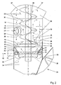
- Fig. 1 shows the device in its entirety.
- the device has a container 1 with a vertical axis 2.
- the container 1 has a wall 3, preferably in a round design, and is arranged vertically aligned with its axis 2.
- the wall 3 of the container 1 is composed of a plurality of cylindrical and / or frusto-conical pieces, in particular so that from bottom to top of the cross-section is increasingly provided, as Fig. 1 shows.
- the container 1 has in its upper region a charging device 4, for example in the form of a funnel, through which the inorganic material soiled with organic material is introduced into the container 1 according to arrow 5.
- the in the operation of the device adjusting water level 6 is indicated.
- a device 7 for removing organic material and liquid adjoins the wall 3 of the container.
- two separate devices may be arranged at different heights, wherein the one device for removing liquid and the other device for the removal of organic material are formed.
- the device for removing organic material is arranged below the device for removing liquid. It connects to a collecting space 8, in which accumulates organic material during operation.
- a supply device 9 is provided for washing water, with the aid of washing water according to arrow 10 is introduced into the interior of the container 1.
- An inlet port 11 is in continuous communication with an annular conduit 12 in the interior of the container 1, via which the task of washing water takes place.
- a protective collar 13 which adjoins the inside of the wall 3 of the container 1, tapers downwardly in a funnel shape and optionally ends in a cylindrical portion, whose lower end is arranged below the ring line 12.
- a free space 14 is created in the gusset between the wall 3 and protective collar 13, which is used to accommodate the annular conduit 12 and determined.
- a shaft 15 which is rotatably driven by a motor 16 and a reduction gear 17.
- the shaft 15 has in a region which can start slightly above the protective collar 13, a screw conveyor 18.
- the screw conveyor 18 may be formed at its lower end via a deflector plate 19 so far closed, so that between the outer diameter of the deflector plate 19 and the inner wall 3 of the container 1, a ring cross-section 20 is formed, from which starting a lifting device 21 acts on the mixture of organically contaminated inorganic material and water.
- the lifting device 21 is designed here as a mechanical lifting device. Essential components of this mechanical lifting device are the shaft 15th and the auger 18. By the action of the lifting device, an upward movement component is exerted on the inorganic and ganic material. The conditions in detail are described below on the basis of Fig. 2 explained.
- the shaft 15 extends with its lower end through the protective collar 13 therethrough. It ends below the same and thus already forms the ring cross-section 20 in the area of the protective collar 13.
- a fluidized layer 22, ie a fluidized bed forms during operation of the device.
- a probe 23 is provided on the outside of the wall 3 of the container 1.
- the probe 23 serves to detect the density of the fluidized bed. From the measured pressure signals, it is possible to deduce the density of the mixture in the fluidized layer 22 and thus the expansion of the fluidized bed.
- These signals are expediently used to convey away the cleaned inorganic material, which passes down through the annular cross-section in the region of the protective collar 13 and settles there, with the aid of a withdrawal device 24 connected to the lower end of the container 1.
- An essential part of the extraction device 24 for the inorganic material is a screw conveyor with shaft 25, screw conveyor 26 and housing 27.
- the screw conveyor with the shaft 25 is driven by a motor 28 and a downstream gear 29 cyclically.
- a chute 30 In the upper region of the housing 27 is a chute 30, with the help of which the discharged cleaned inorganic material is discharged above the water level 6.
- the device is filled with purified inorganic material, ie with sand, with the sand in the bottom Deposits area and a sand cone is formed, which ends approximately in the region of the upper end of the protective collar, so that the inner cross section of the protective collar is more or less completely filled.
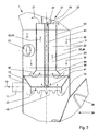
- the supply device 9 is put into operation for washing water, so that washing water according to arrow 10 passes through the inlet port 11 into the annular conduit 12.
- the annular conduit 12 has upwardly directed outlet openings 31.
- the outlet openings 31 are arranged distributed regularly over the circumference of the annular conduit 12.
- the washing water exits through the outlet openings 31 of the annular lines 12 in the space 14 below the protective collar 13. It can be seen that there is no sand, but rather air and / or water in this free space 14, so that even when the device is at a standstill, the outlet openings can neither be clogged, soiled nor galvanized.
- the exiting wash water first reverses its flow direction and then flows under the lower edge of the protective collar 13 as indicated by arrow 33. It takes cleaned sand upwards by continuing to flow upwards through the annular space between protective collar 13 and shaft 15, while in the lower area below the protective collar 13 remains a dotted lines indicated by dashed lines sand pile 34 remains.
- a circulating flow is impressed on the fluidized layer 22, which flow is illustrated by the various arrow representations within the fluidized layer 22.
- the grains of sand in the fluidized layer 22 predominantly according to the arrows 35 move upward, while at a larger radius in the region of the wall 3, a direction of movement according to the arrows 36 downwards predominantly occurs.
- an annular roller flow wherein the flow reversal is illustrated by arrows 37 and 38.
- the flow reversal in the lower region may extend to the annular cross-section at the level of the protective collar 13, while the upper end of the roll flow may also be arranged above the upper end of the screw conveyor 18.
- inorganic material contaminated with organic material is now introduced from above into the container 1, this material being incorporated into the fluidized layer 22. Due to the typical movement of the grains of sand, the impact on each other and the contact with the inner wall 3 of the container, a detachment of the organic material from the inorganic material, comminution and a continued cleaning takes place.
- the lighter organic material is taken up by the wash water, while the sand grains increasingly decrease with decreasing degree of contamination and thereby increasing density down and accumulate in the lower part of the fluidized layer 22.
- Sand grains also pass through the annular space between the shaft 15 and protective collar 13 downwards and are deposited on the sand pile 34.
- the density of the fluidized layer 22 increases. This detects the probe 23, so that outgoing signals are used via a control device to set the trigger 24 in motion and to drive for a predetermined period of time.
- the settled sand pile 34 decreases or its upper limit shifts to a lower level, which again increasingly cleaned sand grains from the fluidized layer 22 down pass and can deposit in the sand heap 34.
- the density of the fluidized layer 22 decreases. With continued loading, a more or less stationary state can occur here, so that the supplied material is continuously cleaned.
- the organic components which have been removed within the fluidized layer 22 and which are comparatively lighter are taken up by the washing water and accumulate in the collecting space 8.
- the shaft 15 of the lifting device 21 can in the region of the collecting space 8, but also in other areas, with stirring arms 39, 40 (FIG. Fig. 1 ) whose task is essentially to repeatedly loosen and break up a solid layer formation of organic material in this area, so that the organic material is discharged via the device 7 together with the washing water.
- stirring arms (not shown) may be provided which, in addition to the action of the required lifting device 21, impart to the sand grains a more or less horizontal component of movement.
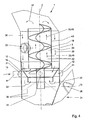
- the lifting device 21 is pneumatically formed.
- the shaft 15 is hollow and has a stepped in diameter extension 41. From above, compressed air is introduced through the interior of the shaft 15 and the extension 41 as indicated by arrow 42. Again, the shaft 15 and the extension 41 is driven, so that the compressed air is supplied via a rotary connection. The compressed air exits at the lower end of the extension 41 according to arrow 47 and, with appropriate washing water supply, reverses its direction of flow.
- a cylinder wall 43 is rotatably connected, which may have an issued catcher collar 44 at its lower end.
- the compressed air flows upwards within the cylinder wall 43 according to arrow 45, so that an upwardly directed component of movement according to arrow 35 is also issued here in the operating state to the sand grains.
- the cylinder wall 43 is open at the top, so that here according to arrow 37, a reversal of the roll flow within the fluidized layer 22 takes place.
- the cylinder wall 43 may be connected to the shaft 15, so be driven in rotation. It is also possible to hang the cylinder wall 43 stationary on the wall 3. In both cases, an annular or cylindrical superimposed flow of the fluidized layer 22 is also impressed here, whereby all those effects are achieved, which are also based on the embodiment according to Fig. 2 occur in a mechanical lifting device 21.
- mechanical and pneumatic lifting devices 21 can be used in combination with one another.
- the wash water supply is somewhat simplified here.
- On the annular conduit 12 is omitted here, so that the free space 14 is used below the protective collar 13 for the distribution of the wash water.
- the lower edge of the protective collar is here provided with prongs or recesses 46, via which the supplied washing water is guided according to the arrows 33 through the space in the protective collar 13 upwards.
- the flow is guided and made uniform, wherein prevail within the cylinder wall 43, the upward flow components, while outside of the cylinder wall 43, the downward flow of the recirculation flow takes place.
- the fluidized bed or the fluidized layer 22 prevails in all two flow cross sections.
- Fig. 4 shows an embodiment in which the cylinder wall 43 of the screw conveyor 18 is associated. It is understood that above the screw conveyor 18, a shaft 15 is provided (not shown), which continues in the lower region of the screw conveyor 18, while a large portion of the height of the screw conveyor 18 is formed wave-less.
- the cylinder wall 43 is connected to the screw conveyor 18 to a co-rotating unit, which is designed to be open at the top and bottom.
- an upwardly directed component of movement according to the arrows 35, 45 prevails inside the cylinder wall 43.
- the annular conduit 12 is here outside the wall 3 arranged circumferentially, while the outlet openings 31 pass through the wall 3.
- the shaft 15 may also differ from the graphical representation of Fig. 4 be provided throughout, like this Fig. 2 shows.
- the fluidized layer 22 is ensured by the interaction of the rising wash water and the lifting device 21. This results in not only the fluidized layer 22, but the imposed circulating flow.
Landscapes
- Chemical & Material Sciences (AREA)
- Chemical Kinetics & Catalysis (AREA)
- Separation Of Solids By Using Liquids Or Pneumatic Power (AREA)
- Processing Of Solid Wastes (AREA)
- Organic Low-Molecular-Weight Compounds And Preparation Thereof (AREA)
- Devices And Processes Conducted In The Presence Of Fluids And Solid Particles (AREA)
- Cleaning By Liquid Or Steam (AREA)
Abstract
Description
Die Erfindung betrifft ein Verfahren und eine Vorrichtung zum Abtrennen von organischem Material von anorganischem Material, insbesondere von organisch verschmutztem Sand von Kläranlagen, mit einem Behälter, der in seinem oberen Bereich eine Beschickungseinrichtung für die Einleitung des verschmutzten anorganischen Materials in den Behälter aufweist, mit einer Im unteren Bereich des Behälters angeordneten Abzugseinrichtung für das abgetrennte anorganische Material, einer Einrichtung zur Abfuhr des organischen Materials und einer Zufuhreinrichtung für Waschwasser im unteren Bereich des Behälters, wobei oberhalb der Zufuhreinrichtung für Waschwasser im Behälter die Trennung des organischen Materials von dem anorganischen Material in einer fluidisierten Schicht erfolgt. Der Behälter der Vorrichtung kann insbesondere in Rundbauweise, aber auch mit polygonartigem Querschnitt erstellt werden. Er besitzt eine vertikale Achse und kann aus zylindrischen sowie kegelförmigen Abschnitten zusammengesetzt sein. Sinnvoll ist eine Querschnittserweiterung von unten nach oben. Die Vorrichtung dient zum Waschen des organisch verschmutzten Sandes. Durch die Abtrennung des organischen Materials wird das anorganische Material, also der Sand, gereinigt. Das abgetrennte organische Material kann zusammen mit dem Waschwasser, alternativ aber auch über eine gesonderte Abzugseinrichtung abgezogen werden.The invention relates to a method and a device for separating organic material from inorganic material, in particular from organic polluted sand of sewage treatment plants, with a container having in its upper region a charging device for the introduction of contaminated inorganic material into the container, with a In the lower portion of the container arranged discharge means for the separated inorganic material, a means for removing the organic material and a supply means for washing water in the lower region of the container, wherein above the supply means for washing water in the container, the separation of the organic material from the inorganic material in one fluidized layer takes place. The container of the device can be created in particular in round design, but also with polygonal cross-section. It has a vertical axis and can be composed of cylindrical and conical sections. It makes sense to extend the cross-section from bottom to top. The device is used for washing the organically polluted sand. By separating the organic material, the inorganic material, ie the sand, is purified. The separated organic material can be withdrawn together with the wash water, but alternatively also via a separate extraction device.
Insbesondere das Material, welches aus dem Sandfang von Kläranlagen oder bei der Kanalreinigung aus dem Kanalnetz entnommen wird, aber auch Straßenkehricht, wie er von Kehrmaschinen aufgenommen wird, enthält neben dem anorganischen Material in Form von Sand, Steinen und dergleichen oft erhebliche Anteile an organischem Material. Um das anorganische Material einer Deponie zuzuführen oder anderweitig wiederverwenden zu können, muss es bis zu gewissem Grade von dem organischem Material befreit werden, um eine kostengünstige Entsorgung durchführen zu können.In particular, the material which is taken from the sand trap of sewage treatment plants or in the sewer cleaning from the sewer system, but also street sweeper, as recorded by sweepers, contains in addition to the inorganic material in the form of sand, stones and the like often considerable amounts of organic material , To the inorganic material In order to be able to feed or otherwise reuse a landfill, it must to a certain extent be freed from the organic material in order to be able to carry out a cost-effective disposal.
Eine Vorrichtung der eingangs beschriebenen Art ist aus der
Aus der
Aus der
Aus der
Der Erfindung liegt die Aufgabe zugrunde, eine Vorrichtung der eingangs beschriebenen Art so weiterzubilden, dass eine hohe Reinigungswirkung erreicht wird, indem das an dem anorganischen Material haftende organische Material von diesem weitgehend gelöst wird und in der Folge das organische Material einerseits und das anorganische Material andererseits getrennt abgeführt werden können. Dabei kommt es darauf an, einen einfachen Aufbau und eine preiswerte Herstellung und einen kostengünstigen Betrieb der Vorrichtung zu ermöglichen.The invention has the object of developing a device of the type described above so that a high cleaning effect is achieved by the adhering to the inorganic material organic material is largely solved by this and subsequently the organic material on the one hand and the inorganic material on the other hand can be removed separately. It is important to allow a simple structure and a low-cost production and a low-cost operation of the device.
Die Aufgabe der Erfindung wird erfindungsgemäß durch die Merkmale der unabhängigen Patentansprüche gelöst.The object of the invention is achieved by the features of the independent claims.
Die Vorrichtung arbeitet, wie im Stand der Technik auch, mit einem Wirbelbett, um die im Vergleich zu einem Festbett effektivere Trennung zwischen anorganischem Material und daran haftendem organischen Material durchzuführen. Es wird also im unteren Bereich des Behälters eine fluidisierte Sandschicht als Wirbelschicht aufrechterhalten, wobei die dadurch initiierte Bewegung der Sandkörner dazu führt, dass organisches Material von anorganischem Material abgelöst, zerkleinert und durch das Waschwasser nach oben ausgetragen wird. Allerdings wird das Wirbelbett nicht nur durch die Zugabe des Waschwassers erzeugt und aufrechterhalten. Es ist vielmehr zusätzlich eine Hebevorrichtung vorgesehen, die zusammen mit der Zufuhreinrichtung für das Waschwasser im unteren Bereich des Behälters die fluidisierte Schicht erzeugt. Die Hebevorrichtung erbringt eine Bewegungskomponente auf die Sandkörner vertikal nach oben, also in der gleichen Richtung, in der auch das zugeführte Waschwasser eine vertikale Bewegungskomponente auf die Sandkörner ausübt. Es wird eine Umlaufströmung in dem Wirbelbett initiiert und so in Bereichen der Wirbelschicht eine Gegenstromwäsche zeugt. Da die Hebevorrichtung zur Erzeugung und Aufrechterhaltung der Wirbelschicht beiträgt, ergibt sich vorteilhaft die Möglichkeit eines geringeren Wasserverbrauchs der Waschwasserzuführung. Die Auslegung der Vorrichtung kann so getroffen sein, dass die Waschwasserzuführung allein eine Überschreitung des Wirbelpunktes noch nicht ermöglicht, sondern hierzu die vertikale Bewegungskomponente der Hebeeinrichtung erforderlich ist. Es ist aber auch möglich, das Waschwasser in größeren Mengen zuzuführen, die alleine ausreicht, den Wirbelpunkt zu überschreiten, um zusätzlich die Umaufströmung und die damit verursachte Gegenstromwäsche im Bereich des Wirbelbettes aufzuprägen. Es entsteht eine verbesserte Abreinigungswirkung. Die Vorrichtung lässt sich mit Vorteil auch dann sinnvoll anwenden, wenn relativ kleine Mengen an mit organischem Material verschmutztem anorganischem Material voneinander abgetrennt werden sollen. Die Hebevorrichtung übt auf das Gemisch aus anorganischem und organischem Material im Bereich des Wirbelbettes eine aufwärtsgerichtete Bewegungskomponente aus. Sie unterscheidet sich damit deutlich von einem Rührwerk, welches auf die Sandkörner eine im Wesentlichen horizontal gerichtete Bewegungskomponente ausübt. Der zusätzliche Einsatz einer Hebevorrichtung hat den weiteren Vorteil, dass das Wirbelbett durch die beschriebene Umlaufströmung auf vorgegebener Bewegungsbahn bewegt wird. Dadurch wird einer Kanalbildung, wie sie für ein Arbeiten im Festbett typisch ist, von vornherein entgegengewirkt.The device operates, as in the prior art, with a fluidized bed to perform the more effective separation between inorganic material and organic material adhering thereto as compared to a fixed bed. Thus, in the lower region of the container, a fluidized sand layer is maintained as a fluidized bed, the movement of the sand grains initiated thereby resulting in organic material being detached from inorganic material, comminuted and discharged upwards by the washing water. However, the fluidized bed is not only generated and maintained by the addition of wash water. Rather, it is additionally provided a lifting device which, together with the supply means for the washing water in the lower region of the container, the fluidized Layer generated. The lifting device provides a component of movement on the grains of sand vertically upwards, ie in the same direction in which also the supplied washing water exerts a vertical component of movement on the grains of sand. It is initiated a circulation flow in the fluidized bed and thus witnesses in areas of the fluidized bed countercurrent washing. Since the lifting device contributes to the generation and maintenance of the fluidized bed, there is advantageously the possibility of a lower water consumption of the washing water supply. The design of the device can be made so that the wash water supply alone does not allow exceeding the vortex point, but this is the vertical movement component of the lifting device is required. But it is also possible to supply the wash water in larger quantities, which alone is sufficient to exceed the vortex point, in addition to impart the upflow and the countercurrent wash thus caused in the field of fluidized bed. The result is an improved cleaning effect. Advantageously, the device can also be used with advantage if relatively small amounts of inorganic material contaminated with organic material are to be separated from one another. The lifting device exerts an upward movement component on the mixture of inorganic and organic material in the area of the fluidized bed. It differs significantly from an agitator, which exerts on the grains of sand a substantially horizontally directed component of movement. The additional use of a lifting device has the further advantage that the fluidized bed is moved by the circulating flow described on a predetermined path of movement. As a result, a channeling, as is typical for working in a fixed bed, counteracted from the outset.
Da die Vorrichtung unter Aufrechterhaltung eines Wirbelbettes arbeitet, besteht - im Gegensatz zu einem Arbeiten in einem Festbett - die Möglichkeit, die Ausdehnung der Wirbelschicht mit einer Drucksonde zu erfassen. Erfindungsgemäß ist eine solche Sonde im Bereich der fluidisierten Schicht an der Wandung des Behälters vorgesehen, um die Ausdehnungshöhe der fluidisierten Schicht durch Steuerung der Abzugseinrichtung für das abgetrennte gereinigte anorganische Material zu steuern, wobei die Abzugseinrichtung als Schneckenfördereinrichtung ausgebildet ist. Die Abzugseinrichtung für das abgetrennte anorganische Material wird taktweise betrieben. Im unteren Bereich des Behälters tritt der gereinigte Sand durch die ringförmige Querschnittsfläche im Schutzkragen nach unten durch. Er lagert sich dort in Form eines Festbettes ab. Bei fortgesetztem Betrieb würde dieses Festbett nach oben wandern. Dies ist nur bedingt zulässig, da die Waschwasserzufuhr nicht behindert werden darf. Um hier ein ordnungsgemäßes Arbeiten sicherzustellen, muss der gereinigte Sand aus seinem Festbett immer wieder entfernt und damit die Höhe des Festbettes durch die Betätigung der Abzugseinrichtung in gewissen Grenzen konstant gehalten werden.Since the device operates while maintaining a fluidized bed, there is the possibility - as opposed to working in a fixed bed - to detect the expansion of the fluidized bed with a pressure probe. According to the invention, such a probe is in the region of the fluidized layer the wall of the container provided to control the expansion height of the fluidized layer by controlling the discharge device for the separated purified inorganic material, wherein the discharge device is designed as a screw conveyor. The discharge device for the separated inorganic material is operated in cycles. In the lower part of the container, the cleaned sand passes down through the annular cross-sectional area in the protective collar. He settles there in the form of a fixed bed. With continued operation, this fixed bed would move upwards. This is only conditionally permissible since the washing water supply must not be hindered. To ensure proper working here, the cleaned sand must be removed from its fixed bed again and again and thus the height of the fixed bed by the operation of the trigger device are kept constant within certain limits.
Eine besonders einfache und preiswerte Realisierung der Hebevorrichtung ergibt sich durch eine senkrecht im Zentrum des Behälters angeordnete Förderschnecke, die über eine Welle angetrieben ist. Die Welle ragt von oben in den Behälter ein, so dass der Antrieb in einfacher Weise oberhalb des Behälters und damit außerhalb des Wasserspiegels angeordnet ist. Die Hebevorrichtung in Form einer solchen Förderschnecke kann gleichzeitig auch mit Rührarmen versehen sein, so dass hier eine gemeinsam antreibbare Einheit geschaffen wird, die sowohl die Funktion der Hebevorrichtung wie auch die Funktion eines Rührwerks erbringen kann. Für die Abreinigungswirkung ist an sich die Anordnung eines Rührwerks nicht erforderlich. Es kann jedoch sinnvoll sein, einen Aufbau einer vergleichsweise festen organischen Schicht oberhalb der Ausdehnungshöhe der Wirbelschicht mit einem Rührarm immer wieder zu lockern bzw. aufzubrechen, damit einerseits die Abfuhr des organischen Materials sichergestellt ist und andererseits kontinuierlich neues abzureinigendes Material, welches durch die Beschickungseinrichtung oben aufgegeben wird, nach unten in die Reinigungszone der Wirbelschicht übertreten kann.A particularly simple and inexpensive realization of the lifting device results from a vertically arranged in the center of the container screw conveyor, which is driven by a shaft. The shaft protrudes from above into the container, so that the drive is arranged in a simple manner above the container and thus outside the water level. The lifting device in the form of such a screw conveyor can be provided at the same time with stirring arms, so that here a jointly drivable unit is provided, which can provide both the function of the lifting device as well as the function of a stirrer. For the Abreinigungswirkung the arrangement of a stirrer is not required per se. However, it may be useful to repeatedly loosen or break up a structure of a comparatively solid organic layer above the expansion height of the fluidized bed with a stirring arm, on the one hand the removal of the organic material is ensured and on the other hand continuously new material to be cleaned off, which by the top loading device is abandoned, can pass down into the cleaning zone of the fluidized bed.
Die Hebevorrichtung kann, wie am Beispiel einer Förderschnecke gezeigt, als mechanisch arbeitende Einrichtung ausgebildet sein. Diese ist wirkungsmäßig im Zentrum bzw. in einem zentralen Ringbereich des Behälters angeordnet, vorzugsweise in einem solchen Bereich des Behälters, der einen zylindrischen vertikalen Abschnitt bildet. Es ist aber auch möglich, die Hebeeinrichtung als pneumatisch wirkende Einrichtung auszubilden, die mit einem Gas, beispielsweise mit Luft, arbeitet, so dass die Hebeeinrichtung einen Druckluftheber darstellt. Die Zuführung der Luft erfolgt zweckmässig von oben. Die Luft wird im unteren Bereich der Wirbelschicht gezielt zum Ausströmen gebracht, also unterhalb des Wasserspiegels, so dass durch die Luft auf das organische und anorganische Material eine vertikale Bewegungskomponente ausgeübt wird, die zusammen mit der Waschwasserzufuhr die Erzeugung und Aufrechterhaltung der Wirbelschicht ermöglicht. Es ist auch möglich, mehrere Hebevorrichtungen in Kombination anzuwenden, beispielsweise eine Kombination aus einer mechanischen und einer pneumatischen Hebevorrichtung. Die Hebevorrichtung kann auch Bestandteil eines Rührwerks mit von oben angetriebener Welle sein, wobei die Hebevorrichtung in erster Linie eine vertikale Bewegungskomponente zur Verfügung stellen muss, während die horizontale Bewegungskomponente des Rührwerks nur zusätzlich genutzt wird.The lifting device can, as shown by the example of a screw conveyor, be designed as a mechanically operating device. This is operatively arranged in the center or in a central annular region of the container, preferably in such a region of the container, which forms a cylindrical vertical section. But it is also possible to form the lifting device as a pneumatically acting device which operates with a gas, for example with air, so that the lifting device is a compressed air lift. The supply of air is conveniently carried out from above. The air is made to flow out in the lower area of the fluidized bed, ie below the water level, so that a vertical component of movement is exerted by the air on the organic and inorganic material, which together with the washing water supply enables the generation and maintenance of the fluidized bed. It is also possible to use several lifting devices in combination, for example a combination of a mechanical and a pneumatic lifting device. The lifting device can also be part of an agitator with shaft driven from above, wherein the lifting device must provide primarily a vertical movement component, while the horizontal movement component of the agitator is used only in addition.
Die Vorrichtung weist eine Zufuhreinrichtung für Waschwasser auf, die etwa als ringförmige Leitung mit Austrittsöffnungen ausgebildet ist. Diese Zufuhreinrichtung ist damit anders ausgebildet als der im Stand der Technik bekannte Lochboden mit nach oben ausgerichteten düsenförmigen Öffnungen, die über die Querschnittsfläche verteilt angeordnet sind. Solche düsenförmigen Öffnungen können verschmutzen oder gar verstopfen, so dass ein partieller Verschluss des Lochbodens möglich ist. Die Zufuhreinrichtung in Form einer ringförmigen Leitung mit Austrittsöffnungen ist dagegen weniger störanfällig. Die Anzahl der Austrittsöffnungen ist grundsätzlich geringer als bei einem Lochboden. Es genügt eine solche ringförmige Leitung, da das Wirbelbett nicht über die gesamte horizontale Querschnittsfläche ausgedehnt wird, sondern gleichsam in einem ringförmigen Spalt zwischen der Hebevorrichtung und dem Innendurchmesser des Behälters erzeugt und aufrechterhalten wird. Das Waschwasser wird damit gezielt in diesem ringförmigen Spalt zugeführt.The device has a supply device for washing water, which is formed approximately as an annular conduit with outlet openings. This supply device is thus designed differently than the well-known in the prior art hole bottom with upwardly directed nozzle-shaped openings which are arranged distributed over the cross-sectional area. Such nozzle-shaped openings can become dirty or even clogged, so that a partial closure of the perforated bottom is possible. The supply device in the form of an annular line with outlet openings, however, is less prone to failure. The number of outlet openings is generally lower than in the case of a perforated floor. It is sufficient such an annular conduit, since the fluidized bed is not extended over the entire horizontal cross-sectional area, but as it is generated and maintained in an annular gap between the lifting device and the inner diameter of the container. The wash water is thus selectively supplied in this annular gap.
Besonders sinnvoll ist es, wenn oberhalb der ringförmigen Leitung an der Innenwandung des Behälters ein Schutzkragen vorgesehen ist, der nach unten einen Freiraum bildet, in welchem die ringförmige Leitung angeordnet ist. Die Austrittsöffnungen der ringförmigen Leitung können nach oben in den Freiraum hinein ausgerichtet angeordnet sein. Dieser Freiraum wird in allen Betriebszuständen frei von abgesetztem Sand gehalten, so dass eine Vierschmutzung und ein Zusetzen der Austrittsöffnungen nicht möglich ist. Die Austrittsöffnungen können aber auch seitlich oder nach unten gerichtet an der in dem Freiraum angeordneten ringförmigen Leitung vorgesehen sein. Der Schutzkragen ist so gestaltet, dass das Waschwasser nach seinem Austritt aus den Austrittsöffnungen der ringförmigen Leitung einen Strömungpfad beschreibt, der zunächst oder auf seinem Weg nach unten gerichtet ist, seine Bewegungsrichtung dann umkehrt und durch den Raum nach oben abströmt, der von dem Schutzkragen eingeschlossen wird. Dabei ist es zweckmässig, dass die Welle der Hebeeinrichtung oder die Zufuhr einer mit Luft arbeitenden Hebeeinrichtung bis unter die ringförmige Leitung reichend vorgesehen ist, so dass bereits im Bereich der Aufwärtsströmung des Waschwassers ein Ringquerschnitt gebildet ist. Wenn die Hebevorrichtung als Förderschnecke ausgebildet ist, kann am unteren Ende der Förderschnecke eine Prallplatte vorgesehen sein, deren Außendurchmesser mit dem Außendurchmesser der Förderwendel der Förderschnecke übereinstimmt. Auch dies dient der Ausbildung eines ringförmigen Querschnittes für die Erzeugung des Wirbelbettes mit der überlagerten Umlaufströmung. Das Waschwasser wird damit auf den Ringquerschnitt konzentriert und die Abweisplatte für das aufströmende Waschwasser verbessert die Hebewirkung der Förderschnecke.It is particularly useful if a protective collar is provided above the annular line on the inner wall of the container, which forms a free space down, in which the annular conduit is arranged. The outlet openings of the annular conduit can be arranged oriented upward into the free space. This space is kept free of settled sand in all operating conditions, so that a four-pollution and clogging of the outlet openings is not possible. The outlet openings may also be provided laterally or downwardly directed to the arranged in the free space annular conduit. The protective collar is designed so that the wash water, after exiting the outlet openings of the annular conduit, describes a flow path which is directed initially or on its way down, then reverses its direction of movement and flows upwards through the space enclosed by the protective collar becomes. It is expedient that the shaft of the lifting device or the supply of a working with air lifting device is provided reaching below the annular conduit, so that even in the region of the upward flow of the wash water a ring cross-section is formed. If the lifting device is designed as a screw conveyor, a baffle plate may be provided at the lower end of the screw conveyor, whose outer diameter coincides with the outer diameter of the conveyor spiral of the screw conveyor. This also serves to form an annular cross-section for the production of the fluidized bed with the superimposed circulating flow. The washing water is thus concentrated on the ring cross-section and the deflector plate for the rising wash water improves the lifting effect of the screw conveyor.
Im Folgenden wird die Erfindung anhand in den Figuren dargestellter bevorzugter Ausführungsbeispiele weiter erläutert und beschrieben.
- Fig. 1
- zeigt eine schematisierte Seitenansicht der gesamten Vorrich- tung.
- Fig. 2
- zeigt einen Detailausschnitt, teilweise geschnitten, gemäss der Ausführungsform der
Fig. 1 der Vorrichtung. - Fig. 3
- zeigt eine ähnliche Schnittdarstellung wie
Fig. 2 , jedoch bei ei- ner anderen Ausführungsform. - Fig. 4
- zeigt eine ähnliche Schnittdarstellung wie die
Fig. 2 und 3 , je- doch bei einer weiteren Ausführungsform.
- Fig. 1
- shows a schematic side view of the entire Vorrich- device.
- Fig. 2
- shows a detail, partially in section, according to the embodiment of the
Fig. 1 the device. - Fig. 3
- shows a similar sectional view as
Fig. 2 but in another embodiment. - Fig. 4
- shows a similar sectional view like the
Fig. 2 and3 but in a further embodiment.
Im unteren Bereich des Behälters 1 ist eine Zufuhreinrichtung 9 für Waschwasser vorgesehen, mit deren Hilfe Waschwasser gemäss Pfeil 10 in das Innere des Behälters 1 eingeleitet wird. Ein Einlassstutzen 11 steht in kontinuierlicher Verbindung zu einer ringförmigen Leitung 12 im Inneren des Behälters 1, über die die Aufgabe des Waschwassers erfolgt.In the lower part of the
Oberhalb der ringförmigen Leitung 12 befindet sich ein Schutzkragen 13, der innen an die Wandung 3 des Behälters 1 anschließt, sich nach unten trichterförmig verjüngt und gegebenenfalls in einem zylindrischen Abschnitt endet, dessen unteres Ende unterhalb der Ringleitung 12 angeordnet ist. Damit wird in dem Zwickel zwischen Wandung 3 und Schutzkragen 13 ein Freiraum 14 geschaffen, der zur Unterbringung der ringförmigen Leitung 12 herangezogen und bestimmt ist.Above the
Von oben reicht in den Behälter 1 eine Welle 15, die über einen Motor 16 und ein Untersetzungsgetriebe 17 rotierend antreibbar ist. Die Welle 15 besitzt in einem Bereich, der etwas oberhalb des Schutzkragens 13 beginnen kann, eine Förderschnecke 18. Die Förderschnecke 18 kann an ihrem unteren Ende über eine Abweisplatte 19 insoweit geschlossen ausgebildet sein, so dass zwischen dem Außendurchmesser der Abweisplatte 19 und der inneren Wandung 3 des Behälters 1 ein Ringquerschnitt 20 gebildet wird, von dem ausgehend nach oben eine Hebevorrichtung 21 auf das Gemisch organisch verschmutzten anorganischen Materials und Wasser einwirkt. Die Hebevorrichtung 21 ist hier als mechanische Hebevorrichtung ausgebildet. Wesentliche Bestandteile dieser mechanischen Hebevorrichtung sind die Welle 15 und die Förderschnecke 18. Durch die Wirkung der Hebevorrichtung wird eine aufwärtsgerichtete Bewegungskomponente auf das anorganische und ganische Material ausgeübt. Die Verhältnisse im Einzelnen werden nachfolgend anhand der
Etwa zwischen dem Schutzkragen 13 bis zum Ende der Hebevorrichtung 21 bzw. der Förderschnecke 18 bzw. geringfügig darüber hinaus bildet sich beim Betrieb der Vorrichtung eine fluidisierte Schicht 22, also ein Wirbelbett aus. Relativ zur Höhe bzw. Ausdehnung der fluidisierten Schicht 22 ist außen an der Wandung 3 des Behälters 1 eine Sonde 23 vorgesehen. Die Sonde 23 dient der Erfassung der Dichte der Wirbelschicht. Aus den gemessenen Drucksignalen kann ein Rückschluss auf die Dichte des Gemisches in der fluidisierten Schicht 22 und damit auf die Ausdehnung der Wirbelschicht folgen. Diese Signale werden zweckmässig dazu benutzt, das gereinigte anorganische Material, welches durch den ringförmigen Querschnitt im Bereich des Schutzkragens 13 nach unten durchtritt und sich dort ablagert, mit Hilfe einer am unteren Ende des Behälters 1 angeschlossenen Abzugseinrichtung 24 schräg nach oben hinwegzufördern. Wesentlicher Bestandteil der Abzugseinrichtung 24 für das anorganische Material ist eine Schneckenfördereinrichtung mit Welle 25, Förderschnecke 26 sowie Gehäuse 27. Die Schneckenfördereinrichtung mit der Welle 25 wird über einen Motor 28 und ein nachgeschaltetes Getriebe 29 taktweise angetrieben. Im oberen Bereich des Gehäuses 27 befindet sich eine Schurre 30, mit deren Hilfe das abgeförderte gereinigte anorganische Material oberhalb des Wasserspiegels 6 abgegeben wird.For example, between the
Anhand der
Über die Beschickungseinrichtung 4 wird nun mit organischem Material verschmutztes anorganisches Material von oben in den Behälter 1 aufgegeben, wobei sich dieses Material in die fluidisierte Schicht 22 einlagert. Durch die typische Bewegung der Sandkörner, das Auftreffen aufeinander sowie den Kontakt mit der inneren Wandung 3 des Behälters erfolgt ein Loslösen des organischen Materials von dem anorganischen Material, eine Zerkleinerung sowie eine fortgesetzte Reinigung. Das leichtere organische Material wird von dem Waschwasser nach oben mitgenommen, während die Sandkörner mit abnehmendem Verschmutzungsgrad und dabei insgesamt zunehmender Dichte vermehrt nach unten durchsinken und sich im unteren Bereich der fluidisierten Schicht 22 ansammeln. Dabei treten Sandkörner auch durch den Ringraum zwischen Welle 15 und Schutzkragen 13 nach unten durch und lagern sich auf dem Sandhaufen 34 auf. Mit diesem Herausführen von Sandkörnern nach unten unter fortgesetzter Beschickung steigt die Dichte der fluidisierten Schicht 22 an. Dies erkennt die Sonde 23, so dass davon ausgehende Signale über eine Steuereinrichtung dazu benutzt werden, um die Abzugseinrichtung 24 in Gang zu setzen und für eine vorgegebene Zeitspanne anzutreiben. Damit verkleinert sich der abgesetzte Sandhaufen 34 bzw. seine Obergrenze verlagert sich auf ein tieferes Niveau, wodurch wieder vermehrt gereinigte Sandkörner aus der fluidisierten Schicht 22 nach unten durchtreten und sich im Bereich des Sandhaufens 34 ablagern können. Damit verringert sich wiederum die Dichte der fluidisierten Schicht 22. Bei fortgesetzter Beschickung kann sich hier ein mehr oder weniger stationärer Zustand einstellen, so dass das zugeführte Material kontinuierlich abgereinigt wird.Via the
Die innerhalb der fluidisierten Schicht 22 abgelösten organischen Bestandteile, die vergleichsweise leichter sind, werden von dem Waschwasser nach oben mitgenommen und reichem sich in dem Sammelraum 8 an. Die Welle 15 der Hebevorrichtung 21 kann im Bereich des Sammelraums 8, aber auch in anderen Bereichen, mit Rührarmen 39, 40 (
Bei der Ausführungsform gemäss
Die Waschwasserzufuhr ist hier etwas vereinfacht ausgebildet. Auf die ringförmige Leitung 12 ist hier verzichtet, so dass der Freiraum 14 unterhalb des Schutzkragens 13 für die Verteilung des Waschwassers genutzt wird. Die untere Kante des Schutzkragens ist hier mit Zacken bzw. Ausnehmungen 46 versehen, über die das zugeführte Waschwasser gemäss den Pfeilen 33 durch den Raum in dem Schutzkragen 13 nach oben geführt wird. Durch die Zylinderwandung 43 wird die Strömung geführt und vergleichmäßigt, wobei innerhalb der Zylinderwandung 43 die aufwärtsgerichteten Strömungskomponenten überwiegen, während außerhalb der Zylinderwandung 43 die Abwärtsströmung der Umwälzströmung stattfindet. In allen beiden Strömungsquerschnitten herrscht natürlich die Wirbelschicht bzw. die fluidisierte Schicht 22 vor.The wash water supply is somewhat simplified here. On the
Bei allen Ausführungsformen wird die fluidisierte Schicht 22 durch das Zusammenwirken des aufströmenden Waschwassers und der Hebevorrichtung 21 sichergestellt. Damit ergibt sich nicht nur die fluidisierte Schicht 22, sondem die aufgeprägte Umwälzströmung.In all embodiments, the
Claims (13)
- A method for separating organic material from inorganic material, particularly sand polluted with organic material coming from sewage treatment plants, wherein polluted inorganic material is introduced into a container (1) and the separated inorganic material is discharged in the lower portion of the container (1) and the organic material is discharged in the upper portion of the container (1) and cleaning water is introduced in the lower portion of the container (1) wherein the separation of the organic material from inorganic material is executed in a fluidized layer (22) above the charging apparatus for the cleaning water in the container (1) and a lifting apparatus (21) is provided that is operative in the area of the fluidized layer (22), by means of which lifting apparatus (21) the mixture of inorganic and organic material is subjected to an upwardly directed component of movement in the area of the turbulent bed of the fluidized layer (22), and that the charging apparatus for the cleaning water and the lifting apparatus (21) are coordinated such that in operation they create the fluidized layer (22) by cooperation of the upwardly flowing cleaning water and the lifting apparatus (21), and that the pressure of the fluidized layer (22) is measured and the discharge of the separated inorganic material is carried out by means of a conveyer spiral that is controlled dependent on the pressure.
- The method according to claim 1, characterized in that the mixture of inorganic and organic material is lifted up mechanically or pneumatically.
- The method according to claim 1 or 2, characterized in that the cleaning water is charged in an annular form.
- The method according to at least one of the foregoing claims, characterized in that the separated inorganic material is discharged in phases.
- An apparatus for separating organic material from inorganic material, particularly sand polluted with organic material coming from sewage treatment plants, with a container (1) having a feeding apparatus (4) for the introduction of polluted inorganic material into said container (1), with a discharging apparatus (24) arranged in the lower portion of the container (1) for the separated inorganic material, an apparatus (7) for the removal of the organic material and a charging apparatus (9) for the cleaning water in the lower portion of the container (1), wherein the separation of the organic material from inorganic material is executed in a fluidized layer (22) above the charging apparatus (9) in the container (1), and a lifting apparatus (21) is provided that is operative in the area of the fluidized layer (22) and that the charging apparatus (9) for the cleaning water in the lower portion of the container (1) and the lifting apparatus (21) are coordinated such that in operation they create the fluidized layer (22) by cooperation of the upwardly flowing cleaning water and the lifting apparatus (21), and that in the area of the fluidized layer (22) a probe (23) is provided at one side (3) of the container (1), which probe is connected to the discharging apparatus (24) via a control device for the control of the discharging apparatus (24) for the separated inorganic material, the discharging apparatus (24) being designed as a conveyer spiral.
- The apparatus according to claim 5, characterized in that said lifting apparatus (21) includes a conveyor spiral (18) being located vertically in the center portion of said container (1) and being driven by a shaft (15).
- The apparatus according to claim 5 or 6, characterized in that said lifting apparatus (21) is designed as a pneumatic lifter.
- The apparatus according to at least one of claims 5 to 7, characterized in that said lifting apparatus (21) is designed as a part of a stirring device with a shaft (15) that is driven from the top.
- The apparatus according to at least one of claims 5 to 8, characterized in that said charging apparatus (9) for cleaning water is designed as an annular conduit (12) including a plurality of exiting openings (31).
- The apparatus according to claim 9, characterized in that a protecting collar (13) is provided above said annular conduit (12) and at the inner wall of said container (1) forming a free space (14), and that said exiting openings (31) of said annular conduit (12) are arranged directing upwards into the free space (14).
- The apparatus according to at least one of claims 9 or 10, characterized in that said shaft (15) of said lifting apparatus (21) is provided to extend below said annular conduit (12) such that an annular cross-section (20) for an upward flow of the cleaning water is formed.
- The apparatus according to at least one of claims 5 to 11, characterized in that the shaft (15) carrying said conveyor spiral (18) includes a deflecting plate (19) for the cleaning water flowing upwardly.
- The apparatus according to at least one of claims 5 to 12, characterized in that said shaft (15) carrying the lifting apparatus (21) further includes stirring arms (39, 40).
Priority Applications (1)
| Application Number | Priority Date | Filing Date | Title |
|---|---|---|---|
| PL04021875T PL1516672T3 (en) | 2003-09-22 | 2004-09-15 | Method and apparatus for separating of organic from inorganic material |
Applications Claiming Priority (2)
| Application Number | Priority Date | Filing Date | Title |
|---|---|---|---|
| DE10343788A DE10343788A1 (en) | 2003-09-22 | 2003-09-22 | Device for separating organic material from inorganic material |
| DE10343788 | 2003-09-22 |
Publications (2)
| Publication Number | Publication Date |
|---|---|
| EP1516672A1 EP1516672A1 (en) | 2005-03-23 |
| EP1516672B1 true EP1516672B1 (en) | 2011-04-20 |
Family
ID=34177879
Family Applications (1)
| Application Number | Title | Priority Date | Filing Date |
|---|---|---|---|
| EP04021875A Expired - Lifetime EP1516672B1 (en) | 2003-09-22 | 2004-09-15 | Method and apparatus for separating of organic from inorganic material |
Country Status (8)
| Country | Link |
|---|---|
| US (1) | US7318527B2 (en) |
| EP (1) | EP1516672B1 (en) |
| JP (1) | JP2005095890A (en) |
| CN (1) | CN1600439A (en) |
| AT (1) | ATE506123T1 (en) |
| DE (2) | DE10343788A1 (en) |
| ES (1) | ES2364879T3 (en) |
| PL (1) | PL1516672T3 (en) |
Families Citing this family (14)
| Publication number | Priority date | Publication date | Assignee | Title |
|---|---|---|---|---|
| US7699177B2 (en) * | 2006-03-20 | 2010-04-20 | Parkson Corporation | Method and apparatus for washing sand |
| US7954642B2 (en) * | 2008-09-26 | 2011-06-07 | U Chicago Argonne, Llc | Process and apparatus for separating solid mixtures |
| CN201389491Y (en) * | 2009-04-07 | 2010-01-27 | 陈文宏 | Sand guiding and washing machine |
| CN101912758B (en) * | 2010-08-03 | 2013-11-06 | 沈安平 | V-shaped reaction kettle |
| CN102039216A (en) * | 2010-09-01 | 2011-05-04 | 王银河 | Organic waste mixing slag remover |
| US8730243B2 (en) | 2011-01-19 | 2014-05-20 | General Electric Company | Systems, methods, and user interfaces for displaying waveform information |
| CN102205262B (en) * | 2011-05-17 | 2014-02-26 | 中国科学院过程工程研究所 | Liquid-solid interference fluidized bed separator, its separation method and application |
| US9809475B2 (en) | 2012-05-07 | 2017-11-07 | Aqwise-Wise Water Technologies Ltd | Accumulated residue removal from carriers used in a water treatment system |
| DE102015112254A1 (en) * | 2015-07-28 | 2017-02-02 | Bta International Gmbh | Hydrodynamic heavy material separation of a slurry |
| US10441958B2 (en) * | 2015-08-28 | 2019-10-15 | Hunter Process Technologies Pty Limited | System, method and apparatus for froth flotation |
| GB2556038A (en) * | 2016-11-10 | 2018-05-23 | Henry Coulton Richard | Separator apparatus and method |
| CN117123558A (en) * | 2023-09-15 | 2023-11-28 | 安徽富春色纺有限公司 | Sand grain cleaning device and cleaning method thereof |
| CN117963574B (en) * | 2024-03-29 | 2024-07-23 | 巴中碳原子新材料科技有限公司 | Discharger with negative pressure function |
| EP4628183A1 (en) | 2024-04-02 | 2025-10-08 | Stjernholm A/S | A sand-manure liquid separation plant, a use of the plant, and a method of using the plant |
Family Cites Families (14)
| Publication number | Priority date | Publication date | Assignee | Title |
|---|---|---|---|---|
| US630309A (en) * | 1897-12-24 | 1899-08-08 | Albert Aeberg | Apparatus for cleaning paper-pulp. |
| US964261A (en) * | 1910-03-14 | 1910-07-12 | Frank G Janney | Ore-classifier. |
| US1035145A (en) * | 1912-04-05 | 1912-08-13 | Lewis L Beeken | Hydraulic classifier. |
| US1277145A (en) * | 1917-10-30 | 1918-08-27 | Leroy E Sowers | Separator for separating manganese dioxid from ores containing the same. |
| US2519781A (en) * | 1946-09-30 | 1950-08-22 | Alexander B Morris | Apparatus for cleaning and/or grading for size, sand, or other similar substances |
| US4124497A (en) * | 1976-07-02 | 1978-11-07 | Hulegard Trueman L | Apparatus for separating mineral and the like from earth and the like |
| US5167375A (en) * | 1988-04-04 | 1992-12-01 | Datta Rabinder S | Apparatus for mineral matter separation |
| IT1241887B (en) * | 1990-08-02 | 1994-02-01 | Ferrero Spa | WET SEPARATOR FOR DISCRIMINATION IN AT LEAST TWO FRACTIONS OF HETEROGENEOUS MIXTURES OF BODIES OF DIFFERENT DENSITIES DISPERSED IN A FLUID AND PARTICULARLY IN WATER |
| AT399141B (en) * | 1993-08-13 | 1995-03-27 | Anlagenbau Franz Zierler | METHOD AND DEVICE FOR SEPARATING SAND FROM WASTE WATER LOADED WITH SAND AND ORGANIC SUBSTANCES |
| DE4415647C2 (en) | 1994-05-04 | 1996-10-02 | Huber Hans Gmbh Maschinen Und | Device for separating inorganic material contaminated with organic material from a liquid |
| DE29614456U1 (en) * | 1996-08-21 | 1996-11-14 | Feierabend, Andreas, 45326 Essen | Device for cleaning and separating sand from a sand / liquid mixture, in particular sand / water mixture |
| DE19805451A1 (en) * | 1998-02-11 | 1999-08-19 | Bormet Maschinenbau Gmbh | Refuse washer for the removal of toxic substances |
| DE19844006A1 (en) * | 1998-09-25 | 2000-04-06 | Strate Technologie Fuer Abwass | Process and assembly to separate and wash sand particles in a waste water treatment plant renders mineral sand fit for disposal to an open site |
| US6250473B1 (en) * | 1998-11-17 | 2001-06-26 | Firstenergy Ventures Corp. | Method and apparatus for separating fast settling particles from slow settling particles |
-
2003
- 2003-09-22 DE DE10343788A patent/DE10343788A1/en not_active Withdrawn
-
2004
- 2004-09-15 DE DE502004012411T patent/DE502004012411D1/en not_active Expired - Lifetime
- 2004-09-15 AT AT04021875T patent/ATE506123T1/en active
- 2004-09-15 EP EP04021875A patent/EP1516672B1/en not_active Expired - Lifetime
- 2004-09-15 ES ES04021875T patent/ES2364879T3/en not_active Expired - Lifetime
- 2004-09-15 PL PL04021875T patent/PL1516672T3/en unknown
- 2004-09-21 JP JP2004273478A patent/JP2005095890A/en not_active Withdrawn
- 2004-09-21 US US10/946,417 patent/US7318527B2/en not_active Expired - Lifetime
- 2004-09-22 CN CNA2004100824775A patent/CN1600439A/en active Pending
Also Published As
| Publication number | Publication date |
|---|---|
| US20050061715A1 (en) | 2005-03-24 |
| CN1600439A (en) | 2005-03-30 |
| DE502004012411D1 (en) | 2011-06-01 |
| PL1516672T3 (en) | 2011-09-30 |
| EP1516672A1 (en) | 2005-03-23 |
| JP2005095890A (en) | 2005-04-14 |
| DE10343788A1 (en) | 2005-04-28 |
| ATE506123T1 (en) | 2011-05-15 |
| ES2364879T3 (en) | 2011-09-15 |
| US7318527B2 (en) | 2008-01-15 |
Similar Documents
| Publication | Publication Date | Title |
|---|---|---|
| EP1516672B1 (en) | Method and apparatus for separating of organic from inorganic material | |
| EP2012901B1 (en) | Process and apparatus for removing coarse solids from a viscous fluid | |
| EP0951327B1 (en) | Device for continuous filtration of liquids | |
| EP0592508B2 (en) | Process and device for improving the treatment of sewage solids, sand, rubbish or the like | |
| DE2941439C2 (en) | ||
| DE2042353C3 (en) | Device for filtering liquids | |
| DE4212097C2 (en) | ||
| EP1210987B1 (en) | Device for obtaining coarse and fine fractions from a sand mixture | |
| DE10200599B4 (en) | Device for separating organic and inorganic material from a liquid | |
| EP0927579A2 (en) | Method and device for removing solids from a solid-liquid mixture | |
| EP1137469B1 (en) | Device for separating waste water | |
| EP0811428A2 (en) | Device for separating composite materials suspended in a liquid | |
| EP0048683B1 (en) | Method and apparatus for the purification of pollutant residues | |
| EP1079933B1 (en) | Separation of solids consisting of organic and inorganic material | |
| DE4410969C1 (en) | Separating device for solid/fluid mixtures | |
| DE2444241C3 (en) | Method and device for separating inorganic solids from organic solids from waste water | |
| WO1995019212A1 (en) | Device for cleaning solid materials contained in waste water | |
| DE19619147A1 (en) | Washing press for screened material e.g. gravel | |
| EP0594167A1 (en) | Device for removing separable matter from a liquid flowing in a gutter | |
| EP0732458B1 (en) | Device for removing solids from a fluid/solid mass | |
| DE9209026U1 (en) | Device for improving the treatment of wastewater solids, sand, garbage, etc. | |
| DE102006018774A1 (en) | Cleaning and separating machine for mass-produced parts with has washing fluid in bottom section of holding container, and centrifuge provided in top open region of holding container, with separate supply tank for washing fluid | |
| DE10253133A1 (en) | Method and device for withdrawing suspensions from a reactor | |
| AT34339B (en) | Sorting machine. | |
| DE2042994A1 (en) | Sewage treatment plant working according to the activated sludge process |
Legal Events
| Date | Code | Title | Description |
|---|---|---|---|
| PUAI | Public reference made under article 153(3) epc to a published international application that has entered the european phase |
Free format text: ORIGINAL CODE: 0009012 |
|
| AK | Designated contracting states |
Kind code of ref document: A1 Designated state(s): AT BE BG CH CY CZ DE DK EE ES FI FR GB GR HU IE IT LI LU MC NL PL PT RO SE SI SK TR |
|
| AX | Request for extension of the european patent |
Extension state: AL HR LT LV MK |
|
| 17P | Request for examination filed |
Effective date: 20050222 |
|
| AKX | Designation fees paid |
Designated state(s): AT BE BG CH CY CZ DE DK EE ES FI FR GB GR HU IE IT LI LU MC NL PL PT RO SE SI SK TR |
|
| 17Q | First examination report despatched |
Effective date: 20061227 |
|
| RAP1 | Party data changed (applicant data changed or rights of an application transferred) |
Owner name: HUBER SE |
|
| GRAP | Despatch of communication of intention to grant a patent |
Free format text: ORIGINAL CODE: EPIDOSNIGR1 |
|
| RTI1 | Title (correction) |
Free format text: METHOD AND APPARATUS FOR SEPARATING OF ORGANIC FROM INORGANIC MATERIAL |
|
| GRAS | Grant fee paid |
Free format text: ORIGINAL CODE: EPIDOSNIGR3 |
|
| GRAA | (expected) grant |
Free format text: ORIGINAL CODE: 0009210 |
|
| AK | Designated contracting states |
Kind code of ref document: B1 Designated state(s): AT BE BG CH CY CZ DE DK EE ES FI FR GB GR HU IE IT LI LU MC NL PL PT RO SE SI SK TR |
|
| REG | Reference to a national code |
Ref country code: GB Ref legal event code: FG4D Free format text: NOT ENGLISH |
|
| REG | Reference to a national code |
Ref country code: CH Ref legal event code: EP |
|
| REG | Reference to a national code |
Ref country code: IE Ref legal event code: FG4D Free format text: LANGUAGE OF EP DOCUMENT: GERMAN |
|
| REF | Corresponds to: |
Ref document number: 502004012411 Country of ref document: DE Date of ref document: 20110601 Kind code of ref document: P |
|
| REG | Reference to a national code |
Ref country code: DE Ref legal event code: R096 Ref document number: 502004012411 Country of ref document: DE Effective date: 20110601 |
|
| REG | Reference to a national code |
Ref country code: SE Ref legal event code: TRGR |
|
| REG | Reference to a national code |
Ref country code: NL Ref legal event code: VDEP Effective date: 20110420 |
|
| REG | Reference to a national code |
Ref country code: ES Ref legal event code: FG2A Ref document number: 2364879 Country of ref document: ES Kind code of ref document: T3 Effective date: 20110915 |
|
| REG | Reference to a national code |
Ref country code: PL Ref legal event code: T3 |
|
| PG25 | Lapsed in a contracting state [announced via postgrant information from national office to epo] |
Ref country code: PT Free format text: LAPSE BECAUSE OF FAILURE TO SUBMIT A TRANSLATION OF THE DESCRIPTION OR TO PAY THE FEE WITHIN THE PRESCRIBED TIME-LIMIT Effective date: 20110822 |
|
| REG | Reference to a national code |
Ref country code: IE Ref legal event code: FD4D |
|
| PG25 | Lapsed in a contracting state [announced via postgrant information from national office to epo] |
Ref country code: FI Free format text: LAPSE BECAUSE OF FAILURE TO SUBMIT A TRANSLATION OF THE DESCRIPTION OR TO PAY THE FEE WITHIN THE PRESCRIBED TIME-LIMIT Effective date: 20110420 Ref country code: GR Free format text: LAPSE BECAUSE OF FAILURE TO SUBMIT A TRANSLATION OF THE DESCRIPTION OR TO PAY THE FEE WITHIN THE PRESCRIBED TIME-LIMIT Effective date: 20110721 Ref country code: SI Free format text: LAPSE BECAUSE OF FAILURE TO SUBMIT A TRANSLATION OF THE DESCRIPTION OR TO PAY THE FEE WITHIN THE PRESCRIBED TIME-LIMIT Effective date: 20110420 Ref country code: CY Free format text: LAPSE BECAUSE OF FAILURE TO SUBMIT A TRANSLATION OF THE DESCRIPTION OR TO PAY THE FEE WITHIN THE PRESCRIBED TIME-LIMIT Effective date: 20110420 |
|
| PG25 | Lapsed in a contracting state [announced via postgrant information from national office to epo] |
Ref country code: NL Free format text: LAPSE BECAUSE OF FAILURE TO SUBMIT A TRANSLATION OF THE DESCRIPTION OR TO PAY THE FEE WITHIN THE PRESCRIBED TIME-LIMIT Effective date: 20110420 |
|
| PG25 | Lapsed in a contracting state [announced via postgrant information from national office to epo] |
Ref country code: CZ Free format text: LAPSE BECAUSE OF FAILURE TO SUBMIT A TRANSLATION OF THE DESCRIPTION OR TO PAY THE FEE WITHIN THE PRESCRIBED TIME-LIMIT Effective date: 20110420 Ref country code: IE Free format text: LAPSE BECAUSE OF FAILURE TO SUBMIT A TRANSLATION OF THE DESCRIPTION OR TO PAY THE FEE WITHIN THE PRESCRIBED TIME-LIMIT Effective date: 20110420 Ref country code: EE Free format text: LAPSE BECAUSE OF FAILURE TO SUBMIT A TRANSLATION OF THE DESCRIPTION OR TO PAY THE FEE WITHIN THE PRESCRIBED TIME-LIMIT Effective date: 20110420 |
|
| PLBE | No opposition filed within time limit |
Free format text: ORIGINAL CODE: 0009261 |
|
| STAA | Information on the status of an ep patent application or granted ep patent |
Free format text: STATUS: NO OPPOSITION FILED WITHIN TIME LIMIT |
|
| PG25 | Lapsed in a contracting state [announced via postgrant information from national office to epo] |
Ref country code: RO Free format text: LAPSE BECAUSE OF FAILURE TO SUBMIT A TRANSLATION OF THE DESCRIPTION OR TO PAY THE FEE WITHIN THE PRESCRIBED TIME-LIMIT Effective date: 20110420 Ref country code: DK Free format text: LAPSE BECAUSE OF FAILURE TO SUBMIT A TRANSLATION OF THE DESCRIPTION OR TO PAY THE FEE WITHIN THE PRESCRIBED TIME-LIMIT Effective date: 20110420 Ref country code: SK Free format text: LAPSE BECAUSE OF FAILURE TO SUBMIT A TRANSLATION OF THE DESCRIPTION OR TO PAY THE FEE WITHIN THE PRESCRIBED TIME-LIMIT Effective date: 20110420 |
|
| 26N | No opposition filed |
Effective date: 20120123 |
|
| BERE | Be: lapsed |
Owner name: HUBER SE Effective date: 20110930 |
|
| PG25 | Lapsed in a contracting state [announced via postgrant information from national office to epo] |
Ref country code: MC Free format text: LAPSE BECAUSE OF NON-PAYMENT OF DUE FEES Effective date: 20110930 |
|
| REG | Reference to a national code |
Ref country code: DE Ref legal event code: R097 Ref document number: 502004012411 Country of ref document: DE Effective date: 20120123 |
|
| PG25 | Lapsed in a contracting state [announced via postgrant information from national office to epo] |
Ref country code: IT Free format text: LAPSE BECAUSE OF FAILURE TO SUBMIT A TRANSLATION OF THE DESCRIPTION OR TO PAY THE FEE WITHIN THE PRESCRIBED TIME-LIMIT Effective date: 20110420 |
|
| PG25 | Lapsed in a contracting state [announced via postgrant information from national office to epo] |
Ref country code: BE Free format text: LAPSE BECAUSE OF NON-PAYMENT OF DUE FEES Effective date: 20110930 |
|
| PG25 | Lapsed in a contracting state [announced via postgrant information from national office to epo] |
Ref country code: LU Free format text: LAPSE BECAUSE OF NON-PAYMENT OF DUE FEES Effective date: 20110915 |
|
| PG25 | Lapsed in a contracting state [announced via postgrant information from national office to epo] |
Ref country code: BG Free format text: LAPSE BECAUSE OF FAILURE TO SUBMIT A TRANSLATION OF THE DESCRIPTION OR TO PAY THE FEE WITHIN THE PRESCRIBED TIME-LIMIT Effective date: 20110720 |
|
| PG25 | Lapsed in a contracting state [announced via postgrant information from national office to epo] |
Ref country code: TR Free format text: LAPSE BECAUSE OF FAILURE TO SUBMIT A TRANSLATION OF THE DESCRIPTION OR TO PAY THE FEE WITHIN THE PRESCRIBED TIME-LIMIT Effective date: 20110420 |
|
| PG25 | Lapsed in a contracting state [announced via postgrant information from national office to epo] |
Ref country code: HU Free format text: LAPSE BECAUSE OF FAILURE TO SUBMIT A TRANSLATION OF THE DESCRIPTION OR TO PAY THE FEE WITHIN THE PRESCRIBED TIME-LIMIT Effective date: 20110420 |
|
| PGFP | Annual fee paid to national office [announced via postgrant information from national office to epo] |
Ref country code: ES Payment date: 20150924 Year of fee payment: 12 |
|
| REG | Reference to a national code |
Ref country code: FR Ref legal event code: PLFP Year of fee payment: 13 |
|
| REG | Reference to a national code |
Ref country code: FR Ref legal event code: PLFP Year of fee payment: 14 |
|
| PGFP | Annual fee paid to national office [announced via postgrant information from national office to epo] |
Ref country code: CH Payment date: 20170920 Year of fee payment: 14 |
|
| PGFP | Annual fee paid to national office [announced via postgrant information from national office to epo] |
Ref country code: AT Payment date: 20170921 Year of fee payment: 14 Ref country code: SE Payment date: 20170921 Year of fee payment: 14 |
|
| PG25 | Lapsed in a contracting state [announced via postgrant information from national office to epo] |
Ref country code: ES Free format text: LAPSE BECAUSE OF NON-PAYMENT OF DUE FEES Effective date: 20160916 |
|
| REG | Reference to a national code |
Ref country code: FR Ref legal event code: PLFP Year of fee payment: 15 |
|
| REG | Reference to a national code |
Ref country code: ES Ref legal event code: FD2A Effective date: 20181128 |
|
| REG | Reference to a national code |
Ref country code: SE Ref legal event code: EUG Ref country code: CH Ref legal event code: PL |
|
| REG | Reference to a national code |
Ref country code: AT Ref legal event code: MM01 Ref document number: 506123 Country of ref document: AT Kind code of ref document: T Effective date: 20180915 |
|
| PG25 | Lapsed in a contracting state [announced via postgrant information from national office to epo] |
Ref country code: SE Free format text: LAPSE BECAUSE OF NON-PAYMENT OF DUE FEES Effective date: 20180916 |
|
| PG25 | Lapsed in a contracting state [announced via postgrant information from national office to epo] |
Ref country code: CH Free format text: LAPSE BECAUSE OF NON-PAYMENT OF DUE FEES Effective date: 20180930 Ref country code: LI Free format text: LAPSE BECAUSE OF NON-PAYMENT OF DUE FEES Effective date: 20180930 |
|
| PG25 | Lapsed in a contracting state [announced via postgrant information from national office to epo] |
Ref country code: AT Free format text: LAPSE BECAUSE OF NON-PAYMENT OF DUE FEES Effective date: 20180915 |
|
| PGFP | Annual fee paid to national office [announced via postgrant information from national office to epo] |
Ref country code: GB Payment date: 20220922 Year of fee payment: 19 |
|
| PGFP | Annual fee paid to national office [announced via postgrant information from national office to epo] |
Ref country code: FR Payment date: 20220924 Year of fee payment: 19 |
|
| PGFP | Annual fee paid to national office [announced via postgrant information from national office to epo] |
Ref country code: PL Payment date: 20230828 Year of fee payment: 20 Ref country code: DE Payment date: 20230915 Year of fee payment: 20 |
|
| GBPC | Gb: european patent ceased through non-payment of renewal fee |
Effective date: 20230915 |
|
| PG25 | Lapsed in a contracting state [announced via postgrant information from national office to epo] |
Ref country code: GB Free format text: LAPSE BECAUSE OF NON-PAYMENT OF DUE FEES Effective date: 20230915 |
|
| PG25 | Lapsed in a contracting state [announced via postgrant information from national office to epo] |
Ref country code: GB Free format text: LAPSE BECAUSE OF NON-PAYMENT OF DUE FEES Effective date: 20230915 Ref country code: FR Free format text: LAPSE BECAUSE OF NON-PAYMENT OF DUE FEES Effective date: 20230930 |
|
| REG | Reference to a national code |
Ref country code: DE Ref legal event code: R071 Ref document number: 502004012411 Country of ref document: DE |