EP1516511B1 - Verfahren zum entwurf eines modalen entzerrers für einen niederfrequenten hörbaren bereich insbesondere für dicht positionierte moden - Google Patents
Verfahren zum entwurf eines modalen entzerrers für einen niederfrequenten hörbaren bereich insbesondere für dicht positionierte moden Download PDFInfo
- Publication number
- EP1516511B1 EP1516511B1 EP03735728A EP03735728A EP1516511B1 EP 1516511 B1 EP1516511 B1 EP 1516511B1 EP 03735728 A EP03735728 A EP 03735728A EP 03735728 A EP03735728 A EP 03735728A EP 1516511 B1 EP1516511 B1 EP 1516511B1
- Authority
- EP
- European Patent Office
- Prior art keywords
- modes
- mode
- modal
- response
- frequency
- Prior art date
- Legal status (The legal status is an assumption and is not a legal conclusion. Google has not performed a legal analysis and makes no representation as to the accuracy of the status listed.)
- Expired - Lifetime
Links
Images






Classifications
-
- H—ELECTRICITY
- H03—ELECTRONIC CIRCUITRY
- H03G—CONTROL OF AMPLIFICATION
- H03G5/00—Tone control or bandwidth control in amplifiers
- H03G5/16—Automatic control
- H03G5/165—Equalizers; Volume or gain control in limited frequency bands
-
- H—ELECTRICITY
- H04—ELECTRIC COMMUNICATION TECHNIQUE
- H04R—LOUDSPEAKERS, MICROPHONES, GRAMOPHONE PICK-UPS OR LIKE ACOUSTIC ELECTROMECHANICAL TRANSDUCERS; ELECTRIC HEARING AIDS; PUBLIC ADDRESS SYSTEMS
- H04R3/00—Circuits for transducers
- H04R3/04—Circuits for transducers for correcting frequency response
Definitions
- the invention relates to a method according to the preamble of claim 1 for forming a modal equalizer for a low frequency audible range especially for closely positioned modes.
- Parametric analysis and modeling is an increasingly common task in acoustics and audio.
- Representative examples of the first group, forward simulation for synthesis are room response modeling including artificial reverb design, or just estimation of eigenmodes at low frequencies in room acoustical studies, and modeling of musical instruments.
- the second category, the inverse modeling is common in audio, where equalization of non-ideal response properties is a frequent task in high-quality sound reproduction, as well as prevention of acoustic feedback in sound reinforcement systems.
- the behavior of acoustic/audio systems at low frequencies can often be modeled analytically and parametrized, at least with lumped models, for example low-frequency modal behavior of a rectangular room [1], musical instrument body [2], or loudspeaker enclosure [3].
- lumped models for example low-frequency modal behavior of a rectangular room [1], musical instrument body [2], or loudspeaker enclosure [3].
- For irregular structures and/or higher frequencies it is much more difficult or impossible to find analytical or numerical models that are useful in practice. In such cases it is still possible to measure system responses and to apply signal modeling techniques to analyze, simulate, or real-time synthesize a given response.
- the modal behavior i.e., decomposition of eigenmodes assuming a linear and time-invariant (LTI) system
- LTI time-invariant
- the density of eigenmodes is not necessarily high, but these modes can exhibit complicated details, for example two-stage decay and strong beating in a decaying envelope.
- 2-D and 3-D resonators such as membranes, plates, and enclosed spaces, the modal density increases towards higher frequencies, resulting in dense modal patterns and reverberation type behavior when neighboring eigenmodes overlap essentially.
- the temporal behavior becomes complex, especially in rooms where the direct sound and early reflections are followed by an increasing density of reflections resulting in late reverberation.
- the problem of modeling measured responses may benefit of a time-frequency modeling viewpoint where the properties of auditory perception are also taken into account.
- IIR filters for infinite impulse response can come in two forms: (a) all-pole models where the numerator of Eq. (1) is reduced to a single gain coefficient b 0 or (b) pole-zero models with both the numerator and denominator being non-trivial polynomials of z.
- AR autoregressive
- MA moving average
- ARMA autoregressive moving-average
- Sections 2 and 3 present an overview of AR and ARMA modeling methods and techniques. Examples are given to illustrate the modeling ability and limitations of these basic approaches.
- Section 4 introduces the Frequency-Zooming ARMA (FZ-ARMA) method that is able to analyze high-order systems with overlapping modes and dense modal distributions. The effects of nonidealities, including noise and non-LTI behavior, are discussed.
- Three cases of audio applications that use AR/ARMA/FZ-ARMA methods are described in Section 5, including modeling of measured room responses, inverse modeling and equalization of loudspeaker-room responses, and modeling as well as sound synthesis of musical instruments.
- the impulse response of a resonant system shows one or more exponentially decaying sinusoids.
- Each such 'mode' can be inherently modeled by a complex conjugate pole pair, which suggests AR modeling with corresponding infinite impulse response (IIR) filters.
- IIR infinite impulse response
- LP linear prediction
- r k are the autocorrelation coefficients r x (k) from Eq.(2) for a signal frame under study and P is the order of LP analysis (order of the all-pole model filter).
- Linear predictive analysis is computed in MATLAB by function "lpc”, which first solves the autocorrelation coefficients r k and then inverts the Toeplitz type correlation matrix to yield predictor coefficients a i through levinson recursion function [8].
- FIG.1 A problem with AR modeling of real-world systems, in the formulation described above, is that the method is not able to do time domain fitting to given target response unless the target process is strictly of AR (all-pole) type.
- Figure 1 illustrates this clearly in a simple case of one idealized mode.
- the model response in Fig.1 (e) is a very accurate replica of the target already with model order of 2 (one complex conjugate pole pair). If the initial phase is changed 90 degrees to a damped cosine function, the second order AR model response (solid line) in Fig.1 (f) severely falls off from the given target in Fig.1 (b) .
- ARMA modeling yielding a pole-zero filter, has more modeling power than the AR method. It is however more difficult because no closed-form solutions are available, thus requiring nonlinear optimization.
- ARMA estimation algorithms are iterative, starting from a good AR model and then iterating towards optimal parameter values. As with any nonlinear optimization methods, problems of divergence or convergence to a local optimum may occur, and plain computational problems due to the lack of numerical precision are found.
- Prony's method [20, pp. 226-228] is a stepwise algorithm that fits N+1 first samples of given response exactly, while P poles of the denominator in Eq.(1) take care of tail decay fitting. Because the AR part estimation is of covariance type, the resulting filter can become unstable, even in cases where the target system to be modeled is stable.
- Steiglitz-McBride method [7, pp. 174-177] is an algorithm with iterative prefiltering for least squares fit of an ARMA model of Eq.(1) to a given impulse response or given input-output pair (system identification problem).
- An initial estimate for the denominator can be obtained for example by Prony's method.
- the resulting filter from the Steiglitz-McBride iteration can be unstable especially with high filter orders even for stable target systems.
- the model response starts in good match with the given time domain response (since this is LS fitting) but after some time it starts to explode due to pole(s) outside the unit circle.
- FIG. 2 An illustrative example on how the order of AR modeling (linear prediction) affects the estimated modal frequencies (pole angles) is shown in Fig. 2 .
- the magnitude spectrum of a measured room response is plotted in comparison with a related pole frequency bifurcation map. For lowest orders only the spectral peak ranges become roughly approximated, and for increasing model order these poles split into new pole pairs and groups of poles.
- Linear prediction may yield stable and accurate results with model orders of hundreds or thousands, particularly when the poles are not very close to the unit circle or to each others.
- poles and zeros
- solving for roots of the denominator is typically more problematic than obtaining these polynomials per se.
- Frequency-selective AR and ARMA modeling solves some of these problems.
- the present invention differs from the prior art in that a mode detection function is formed, highest peak angular frequency ⁇ p of the function is found, AR analysis of predefined order is made for identifying the corresponding poles, selecting the pole closest to point e j ⁇ p on the unit circle, decay time of the mode is determined and if it is over a predetermined level, a modal correction filter is designed for this mode, procedure is repeated and if no decay time exceeds over, a cascaded filter is formed from each individual filter.
- the invention offers substantial benefits.
- Frequency warping is a convenient technique when either lowest or highest frequencies require enhanced frequency resolution. This approach can be extended to Kautz filters that exhibit interesting properties of generalized frequency resolution control [23].
- Frequency selective modeling has been applied for example in linear prediction of speech.
- a target response can be low-pass filtered and decimated in order to model the low-frequency part of the response.
- a range of higher frequencies can be modulated down and decimated before similar modeling.
- any subband of a given frequency range can be modeled this way, and finally the resulting parameters (poles and zeros) can be mapped back to the corresponding original frequency range.
- This approach is called here modeling by frequency zooming. It resembles also the multiband techniques used in [16, 17, 24].
- This implies mapping to a new z-domain where poles are scaled by the rule Z i , zoom Z i K zoom
- mappings (5) and (6) yield new poles.
- Eqs.(5) and (6) characterize how the z-domain properties of a given response are changed through modulation and decimation, but the estimated pole-zero pattern of an ARMA model will be obtained only in the next step.
- z ⁇ i z i K zoom ⁇ e j ⁇ arg z i - ⁇ m ⁇ K zoom
- each pole z i must be used as a complex conjugate pair in order to obtain real-valued filters.
- the final step is to combine poles and zeros obtained from different subbands into a full model. This is a non-trivial task but on the other hand, partitioning of the whole problem and recombining again brings increased flexibility. It is advantageous to pick poles and zeros only within the central part of each (overlapping) subband to avoid problems at the boundaries of subbands due to band-limitation.
- the filter orders N and P refer to real-valued filters with complex conjugate pairs constructed from one-sided zeros and poles obtained from the above method.
- the orders are twice the numbers of zeros and poles from the above procedures, respectively.
- Each resynthesized response is computed as the impulse response of the filter that is obtained by combining the complex conjugate poles and zeros from the FZ-ARMA analysis. Notice that the band-limitation in frequency focusing produces compensating zeros (and poles) that show artifacts in the reconstructed impulse response. In a typical case of focusing on a narrow resonance band the reconstructed impulse response has a high-amplitude impulse as its first sample (see also [27]). This has been removed in the resynthesized response simulations of this patent application. This removal has only marginal effect on the spectral properties of the response.
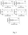
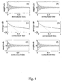
- Fig. 5 The results are displayed in Fig. 5 , which follows the same structure as the previous figures. Now, by looking at subplots (c) and (d) of Fig. 5 it can be seen that the envelopes of the modeled signals (solid lines) differ substantially from those of the noisy signals (dashed lines). Moreover, the resynthesized signals based on the computed models, shown in subplots (e) and (f), are free of visible noise and follow closely their corresponding clean versions, which are depicted in the subplots (a) and (b) of Fig. 3 . Table 1: Parameters in simulation case (A).
- Table 2 Parameters in simulation case (B).
- a primary assumption when applying FZ-ARMA or any LTI system modeling is that the frequencies of modes do not change within the duration of the analyzed segment. If this requirement cannot be satisfied, e.g., in strongly plucked string instrument tones having initial pitch shifting [28], the envelope behavior of the target signal can still be modeled.
- Another way is to apply FZ-ARMA modeling but adopting higher orders for the numerator and denominator so that this can capture the effect of frequency shift.
- ARMA model for the envelope of a modulated and decimated signal (FZ-ENV-ARMA). In that way the envelope behavior can be approximated with a lower model order.
- Simulation case (D) an example that compares the standard FZ-ARMA modeling against the FZ-ENV-ARMA, is shown in Fig. 6 .
- the test signal plotted in subplot (a) is a version of that plotted in Fig. 3 , but now the frequencies of the modes start 50 Hz above the values indicated in Table 1 and then converge exponentially with a time constant of 100 ms to the nominal values.
- the plots on the left column show the original and modeled envelopes for different FZ-ENV-ARMA model orders.
- the plots on the right column do the same but employing FZ-ARMA models.
- nonlinearities Another form of non-LTI behavior are nonlinearities. A small degree of nonlinearity in a system can be accepted, and even quite severe deviation from linear can be tolerated if we accept the fact that the parameters are then signal-dependent, for example dependent on the level of a signal.
- the choice of the FZ-ARMA parameters, i.e., ⁇ m , K zoom , and the ARMA orders N and P, depends on several factors. Considering first the zoom factor, it can be said that the larger K zoom is, the higher the frequency resolution. This favors cases in which the modes are densely distributed in frequency. On the other hand, high values for K zoom imply a more demanding signal decimation procedure and less samples available for modeling in the decimated signal.
- a possible strategy is to define a minimum f s,zoom beforehand and then derive K zoom .
- the criterion may be based on the number of samples that remain in the decimated signal.
- Another natural choice when there are relatively isolated modes or mode groups is to select the frequency range of focusing to cover such a group and its vicinity until neighboring modes or groups start to have influence. It is recommended to to choose the range of focus such that resonance peaks are not placed at the ends of the subband.
- the modulation frequency f m must correspond to the lower edge of the focusing range and the zooming factor K zoom , in relation to sampling rate, determines the zooming bandwith.
- AR/ARMA modeling has many applications in modem audio signal processing. Linear and time-invariant models can be applied for example in room acoustics, sound synthesis, and audio reproduction. Based on the previous theoretical overview and examples, in this section we will take examples from these domains to study the feasibility of the methods, particularly of the FZ-ARMA technique, in several audio applications.
- a challenging application for AR/ARMA modeling is to find compact but perceptually valid approximations for measured (or computed) room impulse responses [12]. This is needed for example in modal analysis of rooms at low frequencies, artificial reverb designs, or equalization of loudspeaker-room responses.
- the original sample rate of 44100 Hz was decimated by a factor of 110 before AR modeling.
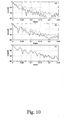
- a comparison with Fig. 8 (a) reveals that the decay times of prominent modes are quite well modeled but many weaker modes are too short or too damped due to insufficient model order.
- FZ-ARMA is a powerful method for accurate modeling of modal behavior in a limited frequency range.
- Figure 9 depicts modeling results of the prominent modal region 33...58 Hz in the response of Fig. 8 (a) .
- the region includes three major modes at frequencies of 37, 46, and 55 Hz.
- Figure 9 shows the decay envelope of the modal region for the original signal (dashed line) and as a result of applying the Steiglitz-McBride method of different orders (solid line). Increasing the filter order improves the envelope fit, but finally it may start to model the background noise envelope.
- Equalization of a loudspeaker response or a loudspeaker-room reproduction chain means correcting the system response closer to desired perceptual or technical criteria.
- MA and ARMA modeling have been reported in the literature in several forms for loudspeaker and in-situ frequency response equalization, both in on-line and off-line formulations [30, 31, 32, 33, 34, 35, 36, 37, 38, 39, 17, 40, 41, 42, 43, 23]
- Equalization of the free-field magnitude response (possibly including the phase response) of a loudspeaker by DSP can be carried out using many known techniques. For highest quality loudspeakers there is hardly any need to improve its free-field response, but the loudspeaker-room combination may benefit greatly from proper equalization.
- step 4 we are only interested in step 4 as a part of batch or iterative analysis. All other steps follow the general scheme described in [44], where the mode search and the decay time estimation were based on a time-frequency representation and fitting of a logarithmic decay plus background noise model using nonlinear optimization. While the previously proposed method is found robust for modes that are separated well enough, strongly overlapping or multiple modes with closely similar frequency are an inherent difficulty of that method. Since AR/ARMA models search for a global optimum and don't try to separate modes, they are potentially a better alternative in such cases.
- mode finding and parameter estimation are carried out iteratively in the following way:
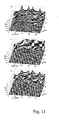
- FIG. 11 A simulated modal equalization, case (I), is illustrated in Fig. 11 .
- a loudspeaker impulse response is filtered to add five simulated modes at frequencies 50, 55, 100, 130, and 180 Hz, with 60 dB modal decay times of 1.4, 0.8, 1.0, 0.8, and 0.7 seconds, respectively.
- the cumulative decay spectrum of this synthetic response is shown in Fig.11 (a).
- Figure 11 (b) proves that the effect of the modes can be cancelled out almost perfectly, leaving the loudspeaker response only, by moving the pole radii to correspond to a very short decay time (about 60 ms) using the procedure described above.
- Figure 11 (c) the result of modal equalization depicted is more appropriate for real room conditions.
- each mode is equalized to 250 ms.
- the most prominent single mode at 46 Hz is equalized by shortening the decay time from a value above 1 second to about 300 ms using the algorithm described above and limiting the search for modes to only one.
- the originally problematic mode decays now clearly faster.
- the equalized response up to 80 Hz has much smoother shape since the modal equalization also affects the magnitude spectrum.
- the decay times of some other modes remain long.
- Multi-mode equalization of the same room, case (K), is shown in Fig. 13 .
- the room is the same as the one analyzed in case (F), Fig. 8 .
- the procedure described above is iterated 100 times, yelding 100 second-order correction filter sections, to shorten the mode decay times.
- the cumulative decay spectrum of the resulting equalized response is illustrated in Fig. 13 (b) .
- the target value for equalized modal decay time (60 dB) has been 150 ms.
- the final step i.e., smooth envelope equalization of the magnitude response
- smooth envelope equalization of the magnitude response is not discussed here since many known techniques could be applied to equalize the magnitude response.
- An interesting choice is, however, to integrate the magnitude equalization phase together with the AR/ARMA modal equalization process.
- the system comprises a listening room 1, which is rather small in relation to the wavelengths to be modified.
- the room 1 is a monitoring room close to a recording studio.
- Typical dimensions for this kind of a room are 6 x 6 x 3m 3 (width x length x height).
- the present invention is most suitable for small rooms. It is not very effective in churches and concert halls.
- the aim of the invention is to design an equalizer 5 for compensating resonance modes in vicinity of a predefined listening position 2.
- Type I implementation modifies the audio signal fed into the primary loudspeaker 3 to compensate for room modes.
- G(z) is the transfer function of the primary radiator from the electrical input to acoustical output
- the new pole pair A'(z) is chosen on the same resonant frequency but closer to the origin, thereby effecting a resonance with a decreased Q value. In this way the modal resonance poles have been moved toward the origin, and the Q value of the mode has been decreased. The sensitivity of this approach will be discussed later with example designs.
- type II method uses a secondary loudspeaker 4 at appropriate position in the room 1 to radiate sound that interacts with the sound field produced by the primary speakers 3. Both speakers 1 and 4 are assumed to be similar in the following treatment, but this is not required for practical implementations.
- the transfer function for the primary radiator 3 is H m (z) and for the secondary radiator 4 H 1 (z).
- the secondary radiator can produce sound level at the listening location in frequencies where the primary radiator can, within the frequency band of interest H 1 f ⁇ 0 , for H m f ⁇ 0
- the magnitude response of the resulting system may be corrected to achieve flat overall response. This correction can be implemented with any of the magnitude response equalization methods.
- the first part of the patent application is a non-theoretical overview of AR and ARMA modeling methods to demonstrate their inherent properties and limitations.
Landscapes
- Physics & Mathematics (AREA)
- Engineering & Computer Science (AREA)
- Acoustics & Sound (AREA)
- Signal Processing (AREA)
- Stereophonic System (AREA)
- Tone Control, Compression And Expansion, Limiting Amplitude (AREA)
- Networks Using Active Elements (AREA)
- Diaphragms For Electromechanical Transducers (AREA)
- Junction Field-Effect Transistors (AREA)
- Piezo-Electric Or Mechanical Vibrators, Or Delay Or Filter Circuits (AREA)
- Measurement Of Mechanical Vibrations Or Ultrasonic Waves (AREA)
- Obtaining Desirable Characteristics In Audible-Bandwidth Transducers (AREA)
- Amplifiers (AREA)
Claims (6)
- Verfahren zum Gestalten eines Moden-Equalizers (5) für einen niederfrequenten akustischen Bereich, insbesondere für Frequenzen unter 200Hz für einen vorbestimmten Raum (1) und einen vorbestimmten Standort (2) darin, aufweisend die Schritte:- Ermitteln der zu entzerrenden Moden mindestens anhand der Mittenfrequenz und der Abklingrate jeder Mode,- Erzeugen einer zeitdiskreten Beschreibung der ermittelten Moden, und- Ermitteln der Equalizer-Filterkoeffizienten auf der Basis der zeitdiskreten Beschreibung der ermittelten Moden, und- Gestalten des Equalizers (5) mittels eines digitalen Filters durch Definieren der Filterkoeffizienten auf Basis der Eigenschaften der Moden,wobei das Verfahren gekennzeichnet ist durch die Schritte- Bilden einer Modendetektionsfunktion (G(Ω)),- Definieren der höchsten Spitzenkreisfrequenz Ωp der Funktion (G(Ω)),- Durchführen einer autoregressiven Analyse einer vorbestimmten Ordnung der minimalen Phasenversion der Zielantwort zum Lösen der Polstellen des Modus, die die höchste Spitzenkreisfrequenz darstellen,- Auswählen der am nächsten zu dem Punkt ejΩp auf dem Einheitskreis befindlichen Polstelle, um mit ihrer komplex Konjugierten die herausragendste Mode darzustellen,- Ermitteln der Abklingzeit der genannten Mode, und wenn sie oberhalb eines vorbestimmten Niveaus liegt, Konstruieren eines Modenkorrekturfilters für diese Mode und Anwenden des genannten Korrekturfilters auf die zu entzerrende Antwort, und- Wiederholen dieser Vorgehensweise, bis keine Abklingzeit das vorbestimmte Niveau überschreitet, und- Gestalten des Equalizers durch Kombinieren all der so erhaltenen Modenkorrekturfilter zu einem stufenförmigen Modenentzerrungsfilter.
- Verfahren nach Anspruch 1, dadurch gekennzeichnet, dass die zeitdiskrete Beschreibung eine Z-Transformation ist.
- Verfahren nach Anspruch 1 oder 2, dadurch gekennzeichnet, dass die Ordnung 50-70 für die AR-Analyse verwendet wird.
- Verfahren nach Anspruch 1 oder 2 oder 3, dadurch gekennzeichnet, dass ein Korrekturfilter zweiter Ordnung der Gleichung

- Verfahren nach einem der Ansprüche 1-4, dadurch gekennzeichnet, dass der Klang der primären Lautsprecher (3) modifiziert wird.
- Verfahren nach einem der Ansprüche 1-4, dadurch gekennzeichnet, dass der Klang der sekundären Lautsprecher (4) modifiziert wird.
Applications Claiming Priority (3)
| Application Number | Priority Date | Filing Date | Title |
|---|---|---|---|
| FI20020865A FI20020865A7 (fi) | 2002-05-07 | 2002-05-07 | Menetelmä matalataajuisen modaalisen ekvalisaattorin suunnittelemiseksi erityisesti lähekkäin sijaitsevia moodeja varten |
| FI20020865 | 2002-05-07 | ||
| PCT/FI2003/000321 WO2003096743A2 (en) | 2002-05-07 | 2003-04-22 | Method for designing a modal equalizer for a low frequency audible range especially for closely positioned modes |
Publications (2)
| Publication Number | Publication Date |
|---|---|
| EP1516511A1 EP1516511A1 (de) | 2005-03-23 |
| EP1516511B1 true EP1516511B1 (de) | 2009-09-23 |
Family
ID=8563898
Family Applications (1)
| Application Number | Title | Priority Date | Filing Date |
|---|---|---|---|
| EP03735728A Expired - Lifetime EP1516511B1 (de) | 2002-05-07 | 2003-04-22 | Verfahren zum entwurf eines modalen entzerrers für einen niederfrequenten hörbaren bereich insbesondere für dicht positionierte moden |
Country Status (8)
| Country | Link |
|---|---|
| US (1) | US7286674B2 (de) |
| EP (1) | EP1516511B1 (de) |
| AT (1) | ATE443976T1 (de) |
| AU (1) | AU2003238101A1 (de) |
| DE (1) | DE60329389D1 (de) |
| ES (1) | ES2333953T3 (de) |
| FI (1) | FI20020865A7 (de) |
| WO (1) | WO2003096743A2 (de) |
Cited By (2)
| Publication number | Priority date | Publication date | Assignee | Title |
|---|---|---|---|---|
| US10490180B2 (en) | 2015-09-02 | 2019-11-26 | Genelec Oy | Control of acoustic modes in a room |
| EP4035148A1 (de) * | 2019-09-27 | 2022-08-03 | Eventide Inc. | Modale halleffekte für einen akustischen raum |
Families Citing this family (17)
| Publication number | Priority date | Publication date | Assignee | Title |
|---|---|---|---|---|
| US7019764B2 (en) * | 2001-09-20 | 2006-03-28 | Genesis Microchip Corporation | Method and apparatus for auto-generation of horizontal synchronization of an analog signal to digital display |
| US7880748B1 (en) * | 2005-08-17 | 2011-02-01 | Apple Inc. | Audio view using 3-dimensional plot |
| WO2007106872A2 (en) * | 2006-03-14 | 2007-09-20 | Harman International Industries, Incorporated | Wide-band equalization system |
| US20110311065A1 (en) | 2006-03-14 | 2011-12-22 | Harman International Industries, Incorporated | Extraction of channels from multichannel signals utilizing stimulus |
| US8363853B2 (en) * | 2007-02-23 | 2013-01-29 | Audyssey Laboratories, Inc. | Room acoustic response modeling and equalization with linear predictive coding and parametric filters |
| EP3998606B8 (de) | 2009-10-21 | 2022-12-07 | Dolby International AB | Überabtastung in einer kombinierten umsetzer-filterbank |
| WO2014171920A1 (en) * | 2013-04-15 | 2014-10-23 | Nuance Communications, Inc. | System and method for addressing acoustic signal reverberation |
| US9848260B2 (en) * | 2013-09-24 | 2017-12-19 | Nuance Communications, Inc. | Wearable communication enhancement device |
| US9426300B2 (en) | 2013-09-27 | 2016-08-23 | Dolby Laboratories Licensing Corporation | Matching reverberation in teleconferencing environments |
| GB201318802D0 (en) * | 2013-10-24 | 2013-12-11 | Linn Prod Ltd | Linn Exakt |
| CN105981412B (zh) * | 2014-03-21 | 2019-05-24 | 华为技术有限公司 | 一种估计总体混合时间的装置和方法 |
| EP2930958A1 (de) * | 2014-04-07 | 2015-10-14 | Harman Becker Automotive Systems GmbH | Schallwellenfelderzeugung |
| DE102014005381B3 (de) * | 2014-04-11 | 2014-12-11 | Wolfgang Klippel | Anordnung und Verfahren zur Identifikation und Kompensation nichtlinearer Partialschwingungen elektromechanischer Wandler |
| US11125043B2 (en) * | 2016-03-23 | 2021-09-21 | University Of Houston System | Model-based monitoring and useful life estimation for blowout preventer annulars |
| US11704983B2 (en) * | 2017-12-22 | 2023-07-18 | Ultrahaptics Ip Ltd | Minimizing unwanted responses in haptic systems |
| EP3985999B1 (de) * | 2020-10-19 | 2024-08-21 | Alps Alpine Co., Ltd. | Verfahren zur konfiguration eines digitalen audiofilters, digitaler audiofilter und tonsystem |
| US12400673B2 (en) * | 2022-08-15 | 2025-08-26 | Mitsubishi Electric Research Laboratories, Inc. | Method and system for reverberation modeling of speech signals |
Family Cites Families (3)
| Publication number | Priority date | Publication date | Assignee | Title |
|---|---|---|---|---|
| JP3240947B2 (ja) * | 1997-01-28 | 2001-12-25 | ヤマハ株式会社 | ハウリング検出器及びハウリングキャンセル装置 |
| US6779404B1 (en) * | 1999-11-03 | 2004-08-24 | Rune Brincker | Method for vibration analysis |
| US20040091120A1 (en) * | 2002-11-12 | 2004-05-13 | Kantor Kenneth L. | Method and apparatus for improving corrective audio equalization |
-
2002
- 2002-05-07 FI FI20020865A patent/FI20020865A7/fi not_active IP Right Cessation
-
2003
- 2003-04-22 DE DE60329389T patent/DE60329389D1/de not_active Expired - Lifetime
- 2003-04-22 AU AU2003238101A patent/AU2003238101A1/en not_active Abandoned
- 2003-04-22 WO PCT/FI2003/000321 patent/WO2003096743A2/en not_active Ceased
- 2003-04-22 EP EP03735728A patent/EP1516511B1/de not_active Expired - Lifetime
- 2003-04-22 ES ES03735728T patent/ES2333953T3/es not_active Expired - Lifetime
- 2003-04-22 US US10/481,114 patent/US7286674B2/en not_active Expired - Lifetime
- 2003-04-22 AT AT03735728T patent/ATE443976T1/de active
Non-Patent Citations (1)
| Title |
|---|
| MÄKIVIRTA A., ANTSALO P., KARJALAINEN M., VÄLIMÄKI V.: "Low-Frequency Modal Equalization of Loudspeaker-Room Responses", AES CONVENTION PAPER 5480 - 111TH CONVENTION NEW YORK, - 24 September 2001 (2001-09-24), Retrieved from the Internet <URL:http://www.aes.org/tmpFiles/elib/20080902/9849.pdf> * |
Cited By (3)
| Publication number | Priority date | Publication date | Assignee | Title |
|---|---|---|---|---|
| US10490180B2 (en) | 2015-09-02 | 2019-11-26 | Genelec Oy | Control of acoustic modes in a room |
| EP4035148A1 (de) * | 2019-09-27 | 2022-08-03 | Eventide Inc. | Modale halleffekte für einen akustischen raum |
| EP4035148B1 (de) * | 2019-09-27 | 2025-08-13 | Eventide Inc. | Modale halleffekte für einen akustischen raum |
Also Published As
| Publication number | Publication date |
|---|---|
| EP1516511A1 (de) | 2005-03-23 |
| ES2333953T3 (es) | 2010-03-03 |
| FI20020865A0 (fi) | 2002-05-07 |
| AU2003238101A1 (en) | 2003-11-11 |
| DE60329389D1 (de) | 2009-11-05 |
| ATE443976T1 (de) | 2009-10-15 |
| US20050175193A1 (en) | 2005-08-11 |
| US7286674B2 (en) | 2007-10-23 |
| FI20020865A7 (fi) | 2003-11-08 |
| WO2003096743A2 (en) | 2003-11-20 |
Similar Documents
| Publication | Publication Date | Title |
|---|---|---|
| Karjalainen et al. | Frequency-zooming ARMA modeling of resonant and reverberant systems | |
| US7286674B2 (en) | Method for designing a modal equalizer for a low frequency audible range especially for closely positioned modes | |
| Smith et al. | Bark and ERB bilinear transforms | |
| Smith et al. | PARSHL: An analysis/synthesis program for non-harmonic sounds based on a sinusoidal representation | |
| RU2554552C2 (ru) | Устройство и способ для разложения входного сигнала с использованием заранее вычисленной эталонной кривой | |
| US7742607B2 (en) | Method for designing a modal equalizer for a low frequency sound reproduction | |
| US9805704B1 (en) | Method and system for artificial reverberation using modal decomposition | |
| EP1066623B1 (de) | Verfahren und vorrichtung zur objektiven qualitätsmessung von audiosignalen | |
| EP0094762A2 (de) | Automatische Zeitbereichs-Ausgleichsvorrichtung für Audiosignale | |
| RU2595896C2 (ru) | Схема контроллера предварительной коррекции аудио с использованием переменного набора поддерживающих громкоговорителей | |
| US8401685B2 (en) | Method for reproducing an audio recording with the simulation of the acoustic characteristics of the recording condition | |
| US20170024495A1 (en) | Method of modeling characteristics of a musical instrument | |
| US9626949B2 (en) | System of modeling characteristics of a musical instrument | |
| Karjalainen et al. | Warped filters and their audio applications | |
| EP4035152B1 (de) | Modusauswahl für modalen hall | |
| Välimäki et al. | Spectral delay filters | |
| Karjalainen et al. | AR/ARMA analysis and modeling of modes in resonant and reverberant systems | |
| US20060129389A1 (en) | Spectrum modeling | |
| Penttinen et al. | New techniques to model reverberant instrument body responses | |
| Maestre et al. | Constrained pole optimization for modal reverberation | |
| Bank | Warped, kautz, and fixed-pole parallel filters: A review | |
| US10019980B1 (en) | Distortion and pitch processing using a modal reverberator architecture | |
| Hahn et al. | Time domain radial filter design for spherical waves | |
| Robel | Adaptive additive modeling with continuous parameter trajectories | |
| Tolonen et al. | Perceptual study of decay parameters in plucked string synthesis |
Legal Events
| Date | Code | Title | Description |
|---|---|---|---|
| PUAI | Public reference made under article 153(3) epc to a published international application that has entered the european phase |
Free format text: ORIGINAL CODE: 0009012 |
|
| 17P | Request for examination filed |
Effective date: 20031124 |
|
| AK | Designated contracting states |
Kind code of ref document: A1 Designated state(s): AT BE BG CH CY CZ DE DK EE ES FI FR GB GR HU IE IT LI LU MC NL PT RO SE SI SK TR |
|
| AX | Request for extension of the european patent |
Extension state: AL LT LV MK |
|
| DAX | Request for extension of the european patent (deleted) | ||
| 17Q | First examination report despatched |
Effective date: 20080908 |
|
| GRAP | Despatch of communication of intention to grant a patent |
Free format text: ORIGINAL CODE: EPIDOSNIGR1 |
|
| GRAS | Grant fee paid |
Free format text: ORIGINAL CODE: EPIDOSNIGR3 |
|
| GRAA | (expected) grant |
Free format text: ORIGINAL CODE: 0009210 |
|
| AK | Designated contracting states |
Kind code of ref document: B1 Designated state(s): AT BE BG CH CY CZ DE DK EE ES FI FR GB GR HU IE IT LI LU MC NL PT RO SE SI SK TR |
|
| REG | Reference to a national code |
Ref country code: GB Ref legal event code: FG4D |
|
| REG | Reference to a national code |
Ref country code: CH Ref legal event code: EP |
|
| REG | Reference to a national code |
Ref country code: IE Ref legal event code: FG4D |
|
| REF | Corresponds to: |
Ref document number: 60329389 Country of ref document: DE Date of ref document: 20091105 Kind code of ref document: P |
|
| REG | Reference to a national code |
Ref country code: CH Ref legal event code: NV Representative=s name: BRAUNPAT BRAUN EDER AG |
|
| PG25 | Lapsed in a contracting state [announced via postgrant information from national office to epo] |
Ref country code: SE Free format text: LAPSE BECAUSE OF FAILURE TO SUBMIT A TRANSLATION OF THE DESCRIPTION OR TO PAY THE FEE WITHIN THE PRESCRIBED TIME-LIMIT Effective date: 20090923 |
|
| PG25 | Lapsed in a contracting state [announced via postgrant information from national office to epo] |
Ref country code: SI Free format text: LAPSE BECAUSE OF FAILURE TO SUBMIT A TRANSLATION OF THE DESCRIPTION OR TO PAY THE FEE WITHIN THE PRESCRIBED TIME-LIMIT Effective date: 20090923 |
|
| NLV1 | Nl: lapsed or annulled due to failure to fulfill the requirements of art. 29p and 29m of the patents act | ||
| REG | Reference to a national code |
Ref country code: ES Ref legal event code: FG2A Ref document number: 2333953 Country of ref document: ES Kind code of ref document: T3 |
|
| PG25 | Lapsed in a contracting state [announced via postgrant information from national office to epo] |
Ref country code: CY Free format text: LAPSE BECAUSE OF FAILURE TO SUBMIT A TRANSLATION OF THE DESCRIPTION OR TO PAY THE FEE WITHIN THE PRESCRIBED TIME-LIMIT Effective date: 20090923 |
|
| PG25 | Lapsed in a contracting state [announced via postgrant information from national office to epo] |
Ref country code: CZ Free format text: LAPSE BECAUSE OF FAILURE TO SUBMIT A TRANSLATION OF THE DESCRIPTION OR TO PAY THE FEE WITHIN THE PRESCRIBED TIME-LIMIT Effective date: 20090923 Ref country code: EE Free format text: LAPSE BECAUSE OF FAILURE TO SUBMIT A TRANSLATION OF THE DESCRIPTION OR TO PAY THE FEE WITHIN THE PRESCRIBED TIME-LIMIT Effective date: 20090923 Ref country code: PT Free format text: LAPSE BECAUSE OF FAILURE TO SUBMIT A TRANSLATION OF THE DESCRIPTION OR TO PAY THE FEE WITHIN THE PRESCRIBED TIME-LIMIT Effective date: 20100125 Ref country code: RO Free format text: LAPSE BECAUSE OF FAILURE TO SUBMIT A TRANSLATION OF THE DESCRIPTION OR TO PAY THE FEE WITHIN THE PRESCRIBED TIME-LIMIT Effective date: 20090923 |
|
| PG25 | Lapsed in a contracting state [announced via postgrant information from national office to epo] |
Ref country code: SK Free format text: LAPSE BECAUSE OF FAILURE TO SUBMIT A TRANSLATION OF THE DESCRIPTION OR TO PAY THE FEE WITHIN THE PRESCRIBED TIME-LIMIT Effective date: 20090923 |
|
| PG25 | Lapsed in a contracting state [announced via postgrant information from national office to epo] |
Ref country code: BE Free format text: LAPSE BECAUSE OF FAILURE TO SUBMIT A TRANSLATION OF THE DESCRIPTION OR TO PAY THE FEE WITHIN THE PRESCRIBED TIME-LIMIT Effective date: 20090923 |
|
| PG25 | Lapsed in a contracting state [announced via postgrant information from national office to epo] |
Ref country code: NL Free format text: LAPSE BECAUSE OF FAILURE TO SUBMIT A TRANSLATION OF THE DESCRIPTION OR TO PAY THE FEE WITHIN THE PRESCRIBED TIME-LIMIT Effective date: 20090923 Ref country code: DK Free format text: LAPSE BECAUSE OF FAILURE TO SUBMIT A TRANSLATION OF THE DESCRIPTION OR TO PAY THE FEE WITHIN THE PRESCRIBED TIME-LIMIT Effective date: 20090923 |
|
| PLBE | No opposition filed within time limit |
Free format text: ORIGINAL CODE: 0009261 |
|
| STAA | Information on the status of an ep patent application or granted ep patent |
Free format text: STATUS: NO OPPOSITION FILED WITHIN TIME LIMIT |
|
| 26N | No opposition filed |
Effective date: 20100624 |
|
| PG25 | Lapsed in a contracting state [announced via postgrant information from national office to epo] |
Ref country code: GR Free format text: LAPSE BECAUSE OF FAILURE TO SUBMIT A TRANSLATION OF THE DESCRIPTION OR TO PAY THE FEE WITHIN THE PRESCRIBED TIME-LIMIT Effective date: 20091224 |
|
| PG25 | Lapsed in a contracting state [announced via postgrant information from national office to epo] |
Ref country code: MC Free format text: LAPSE BECAUSE OF NON-PAYMENT OF DUE FEES Effective date: 20100430 |
|
| PG25 | Lapsed in a contracting state [announced via postgrant information from national office to epo] |
Ref country code: BG Free format text: LAPSE BECAUSE OF FAILURE TO SUBMIT A TRANSLATION OF THE DESCRIPTION OR TO PAY THE FEE WITHIN THE PRESCRIBED TIME-LIMIT Effective date: 20090923 Ref country code: LU Free format text: LAPSE BECAUSE OF NON-PAYMENT OF DUE FEES Effective date: 20100422 Ref country code: HU Free format text: LAPSE BECAUSE OF FAILURE TO SUBMIT A TRANSLATION OF THE DESCRIPTION OR TO PAY THE FEE WITHIN THE PRESCRIBED TIME-LIMIT Effective date: 20100324 |
|
| PG25 | Lapsed in a contracting state [announced via postgrant information from national office to epo] |
Ref country code: TR Free format text: LAPSE BECAUSE OF FAILURE TO SUBMIT A TRANSLATION OF THE DESCRIPTION OR TO PAY THE FEE WITHIN THE PRESCRIBED TIME-LIMIT Effective date: 20090923 |
|
| REG | Reference to a national code |
Ref country code: FR Ref legal event code: PLFP Year of fee payment: 13 |
|
| PGFP | Annual fee paid to national office [announced via postgrant information from national office to epo] |
Ref country code: FI Payment date: 20150423 Year of fee payment: 13 |
|
| REG | Reference to a national code |
Ref country code: FR Ref legal event code: PLFP Year of fee payment: 14 |
|
| PGFP | Annual fee paid to national office [announced via postgrant information from national office to epo] |
Ref country code: CH Payment date: 20160420 Year of fee payment: 14 Ref country code: IE Payment date: 20160421 Year of fee payment: 14 |
|
| PGFP | Annual fee paid to national office [announced via postgrant information from national office to epo] |
Ref country code: AT Payment date: 20160421 Year of fee payment: 14 |
|
| PG25 | Lapsed in a contracting state [announced via postgrant information from national office to epo] |
Ref country code: FI Free format text: LAPSE BECAUSE OF NON-PAYMENT OF DUE FEES Effective date: 20160422 |
|
| REG | Reference to a national code |
Ref country code: FR Ref legal event code: PLFP Year of fee payment: 15 |
|
| REG | Reference to a national code |
Ref country code: CH Ref legal event code: PL |
|
| REG | Reference to a national code |
Ref country code: AT Ref legal event code: MM01 Ref document number: 443976 Country of ref document: AT Kind code of ref document: T Effective date: 20170422 |
|
| REG | Reference to a national code |
Ref country code: IE Ref legal event code: MM4A |
|
| PG25 | Lapsed in a contracting state [announced via postgrant information from national office to epo] |
Ref country code: AT Free format text: LAPSE BECAUSE OF NON-PAYMENT OF DUE FEES Effective date: 20170422 |
|
| PG25 | Lapsed in a contracting state [announced via postgrant information from national office to epo] |
Ref country code: LI Free format text: LAPSE BECAUSE OF NON-PAYMENT OF DUE FEES Effective date: 20170430 Ref country code: CH Free format text: LAPSE BECAUSE OF NON-PAYMENT OF DUE FEES Effective date: 20170430 |
|
| REG | Reference to a national code |
Ref country code: FR Ref legal event code: PLFP Year of fee payment: 16 |
|
| PG25 | Lapsed in a contracting state [announced via postgrant information from national office to epo] |
Ref country code: IE Free format text: LAPSE BECAUSE OF NON-PAYMENT OF DUE FEES Effective date: 20170422 |
|
| PGFP | Annual fee paid to national office [announced via postgrant information from national office to epo] |
Ref country code: IT Payment date: 20190429 Year of fee payment: 17 Ref country code: ES Payment date: 20190521 Year of fee payment: 17 |
|
| REG | Reference to a national code |
Ref country code: ES Ref legal event code: FD2A Effective date: 20210903 |
|
| PG25 | Lapsed in a contracting state [announced via postgrant information from national office to epo] |
Ref country code: IT Free format text: LAPSE BECAUSE OF NON-PAYMENT OF DUE FEES Effective date: 20200422 |
|
| PG25 | Lapsed in a contracting state [announced via postgrant information from national office to epo] |
Ref country code: ES Free format text: LAPSE BECAUSE OF NON-PAYMENT OF DUE FEES Effective date: 20200423 |
|
| PGFP | Annual fee paid to national office [announced via postgrant information from national office to epo] |
Ref country code: GB Payment date: 20220420 Year of fee payment: 20 Ref country code: FR Payment date: 20220420 Year of fee payment: 20 Ref country code: DE Payment date: 20220420 Year of fee payment: 20 |
|
| REG | Reference to a national code |
Ref country code: DE Ref legal event code: R071 Ref document number: 60329389 Country of ref document: DE |
|
| REG | Reference to a national code |
Ref country code: GB Ref legal event code: PE20 Expiry date: 20230421 |
|
| PG25 | Lapsed in a contracting state [announced via postgrant information from national office to epo] |
Ref country code: GB Free format text: LAPSE BECAUSE OF EXPIRATION OF PROTECTION Effective date: 20230421 |