EP1516410B1 - Elektrischer stellantrieb - Google Patents
Elektrischer stellantrieb Download PDFInfo
- Publication number
- EP1516410B1 EP1516410B1 EP03761729A EP03761729A EP1516410B1 EP 1516410 B1 EP1516410 B1 EP 1516410B1 EP 03761729 A EP03761729 A EP 03761729A EP 03761729 A EP03761729 A EP 03761729A EP 1516410 B1 EP1516410 B1 EP 1516410B1
- Authority
- EP
- European Patent Office
- Prior art keywords
- motor
- control device
- connecting piece
- auxiliary
- piece
- Prior art date
- Legal status (The legal status is an assumption and is not a legal conclusion. Google has not performed a legal analysis and makes no representation as to the accuracy of the status listed.)
- Expired - Lifetime
Links
- 230000000295 complement effect Effects 0.000 claims 1
- 230000000717 retained effect Effects 0.000 claims 1
- 239000006185 dispersion Substances 0.000 description 2
- 238000004804 winding Methods 0.000 description 2
- 239000003638 chemical reducing agent Substances 0.000 description 1
- 230000006835 compression Effects 0.000 description 1
- 238000007906 compression Methods 0.000 description 1
- 230000001419 dependent effect Effects 0.000 description 1
- 238000006073 displacement reaction Methods 0.000 description 1
- 239000002184 metal Substances 0.000 description 1
- 238000007789 sealing Methods 0.000 description 1
- 229920002994 synthetic fiber Polymers 0.000 description 1
- 230000000007 visual effect Effects 0.000 description 1
Images

Classifications
-
- H—ELECTRICITY
- H01—ELECTRIC ELEMENTS
- H01R—ELECTRICALLY-CONDUCTIVE CONNECTIONS; STRUCTURAL ASSOCIATIONS OF A PLURALITY OF MUTUALLY-INSULATED ELECTRICAL CONNECTING ELEMENTS; COUPLING DEVICES; CURRENT COLLECTORS
- H01R13/00—Details of coupling devices of the kinds covered by groups H01R12/70 or H01R24/00 - H01R33/00
- H01R13/62—Means for facilitating engagement or disengagement of coupling parts or for holding them in engagement
- H01R13/629—Additional means for facilitating engagement or disengagement of coupling parts, e.g. aligning or guiding means, levers, gas pressure electrical locking indicators, manufacturing tolerances
- H01R13/631—Additional means for facilitating engagement or disengagement of coupling parts, e.g. aligning or guiding means, levers, gas pressure electrical locking indicators, manufacturing tolerances for engagement only
- H01R13/6315—Additional means for facilitating engagement or disengagement of coupling parts, e.g. aligning or guiding means, levers, gas pressure electrical locking indicators, manufacturing tolerances for engagement only allowing relative movement between coupling parts, e.g. floating connection
-
- H—ELECTRICITY
- H02—GENERATION; CONVERSION OR DISTRIBUTION OF ELECTRIC POWER
- H02K—DYNAMO-ELECTRIC MACHINES
- H02K5/00—Casings; Enclosures; Supports
- H02K5/04—Casings or enclosures characterised by the shape, form or construction thereof
- H02K5/22—Auxiliary parts of casings not covered by groups H02K5/06-H02K5/20, e.g. shaped to form connection boxes or terminal boxes
- H02K5/225—Terminal boxes or connection arrangements
Definitions
- the invention relates to a tubular electrical actuator defined according to the preamble of claim 1
- Such actuators are used to operate doors, shutters, or roller blinds.
- the auxiliary connecting piece consists here of a cylindrical piece removably attached to the end of the motor to be connected to the control device, this auxiliary piece containing or being surrounded by a certain length of wire extending the stator winding. motor and carrying lugs to which are fixed the ends of these son.
- the motor more precisely the motor and its gearbox are preferably mounted together by one end of the tube, that which allows the application of the force by the gear, more massive, having a more suitable conformation and causing the smallest displacement under stress .
- the auxiliary connecting piece is then detached from the motor and its lugs are plugged on corresponding lugs of the control device before mounting it in the tube through the other end of the tube.
- the reserve of wound wire contained or carried by the auxiliary piece must therefore be of sufficient length so that the manipulation can be easily performed outside the tube.
- This embodiment has drawbacks. On the one hand, an important length of wire remains free and floating inside the tube and may be injured or pinched. On the other hand, part of this wire is useless to the conduction function of the electric current. Another important disadvantage is that this connection operation can not be automated.
- the object of the invention is to propose a structure that obviates the disadvantages of the structure according to the prior art and, in particular, that makes it possible to automate the assembly of the motor and its control device.
- tubular electric actuator according to the invention is characterized by the characterizing part of claim 1
- connection of the motor and its control device is thus performed automatically when mounting the elements in the tube.
- the tubular actuator shown schematically at the figure 1 comprises, in known manner, a cylindrical metal tube 1 in which a motor 2 associated with a gearbox 3 and a control device 4 for driving the motor 1 are mounted.
- the control device 4 can go from simple automatic shutdown to end of stroke of the engine-driven load to more advanced controls such as an obstacle stop, stopping in the intermediate position or control according to a particular program.
- Such devices are described, for example, in patents EP 0 434 614 , EP 0524152 , EP 0 568 492 and EP 0 671 542 .
- the gearbox 3 has an output shaft 5 for driving the load to be actuated, for example a roller blind, a shutter or a door.
- the control device 4 is electrically connected to the motor 2 by means of an auxiliary connection piece 6 which will be described in more detail in connection with the figure 2 .
- the figure 2 represents the actuator before the connection of the control device 4 to the engine 2.
- the connecting piece 6, made of synthetic material, has a cylindrical pot shape provided with four flexible tabs 7 extending the cylindrical wall and distributed over the circumference of the piece 6. These tabs 7 end with a hook and a ramp for attachment of the part 6 on the end of the control device 4 which has for this purpose a neck 8 having slots 9 in which engage the legs 7 of the auxiliary connecting piece 6.
- the length of the legs 7 between their hook and their base is greater than the thickness of the neck 8.
- the slots 9 extend over an arc substantially greater than the width of the legs 7, such so that the connecting piece 6 is fixed on the control device 4 with an angular play.
- connection piece 6 Inside the connecting piece 6 is mounted a helical spring 10 working in compression between the end of the control device 4 and the bottom of the connecting piece 6 so as to push this piece and maintain the ends in the form of hook of the legs 7 in abutment against the neck 8.
- the shoulder 11 visible at the figure 2 indicates the start of the tabs 7.
- connection piece 6 In its front part, the connection piece 6 is provided with three female lugs 12, 13, 14 connected by wires not shown to the control device 4. This same front face has a circular hole 15.
- the motor 2 is provided with three pins 16, 17, 18 and a finger 19 extending parallel to the axis 20 of the motor and terminated by a conical portion 21.
- the motor 2 and the control device 4 are mounted in the tube 1, the axes of the hole 15 and the finger 19 are at the same distance from the axis 20 of the tube 1.
- Motor 2 and its reducer 3 are first introduced by force into the tube 1 by one of the ends of this tube, that is to say the end A shown in FIG. figure 1 .
- the control device 4 is then presented in front of the other end B of the tube 1 by orienting the latter approximately, by a simple visual cue, the only constraint being that the guide pin 19 of the motor penetrates for sure into the corresponding orifice 15 of the auxiliary connection piece 6.
- the control device 4 is then engaged in the tube 1.
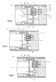
- the conical end 21 of the guide pin 19 enters the orifice 15 of the connection piece 6 and, if necessary, rotates this connecting piece 6 around its axis so as to align the axis of the orifice 15 and the axis of the finger 19 and, consequently, to bring the lugs 12 to 14 opposite the pins 16 to 18, as shown in FIG. figure 5 .
- Pushing is continued on the control device 4 so that the pins 16 to 18 engage in the lugs 12 to 14, as shown in FIG. figure 6 .
- the force of the spring 10 is substantially greater than the force required to introduce the pins in the pods.
- the connecting piece 6 finally comes into abutment against the motor 2, as shown in FIG. figure 6 . The connection is made.
- the control device 4 is not yet fully inserted into the tube 1. It continues to push on the control device 4 until the flange 22 (shown in FIG. figure 1 ) which terminates in abutment against the end B of the tube 1. The further movement of the control device 4 is possible due to the axial play that the connecting piece 6 has with the control device 4. The final position is represented at figure 7 . The connecting piece 6 has moved back relative to the control device 4 by compressing the spring 10.
- the axial clearance makes it possible to ensure in particular an external appearance unit of the actuators and a sealing of the closure of the end B of the tube by the flange 22.
- the axial freedom of the auxiliary connection piece also makes it possible to accept the dispersions inevitable in the axial positioning of the lugs relative to the integral pins of the engine. Indeed, the pins and lugs being in the center of a chain of dimensions including the axial dimensions, the motor, the gearbox, the winding tube and the control device which each have dispersions, it is common that the position Axial of the spindles relative to the pods varies in a range of about 3mm.
- the lugs and pins shown may be replaced by any other pluggable connection means.
- the auxiliary connecting piece could be mounted alternately on the motor instead of being mounted on the control device.
- the connection of the connection piece with one of the elements, motor or control device could be achieved by means other than those shown. It could in particular be mounted friction on a bearing or in a housing of one of the elements, the only requirements to be respected are the angular and axial clearances and a friction force substantially greater than the force required to insert the means of connection of the motor and the control device.
- the angular positioning means could also be made differently.
Landscapes
- Engineering & Computer Science (AREA)
- Power Engineering (AREA)
- Fluid-Damping Devices (AREA)
- Connection Of Motors, Electrical Generators, Mechanical Devices, And The Like (AREA)
- Operating, Guiding And Securing Of Roll- Type Closing Members (AREA)
- Vehicle Body Suspensions (AREA)
- Valve Device For Special Equipments (AREA)
- Apparatus For Radiation Diagnosis (AREA)
- Lock And Its Accessories (AREA)
Claims (4)
- Rohrförmiger elektrischer Antrieb, mit einem Rohr (1), in welchem ein erstes Element mit einem Motor (2) und ein zweites Element aus einer Steuervorrichtung (4) für den Motor eingebracht sind, wobei diese Elemente elektrisch über ein Hilfsverbindungsstück (6) miteinander verbunden sind, welches an einem der Elemente angebracht ist und mit steckbaren Mitteln (12, 13, 14) zur Verbindung ausgestattet ist, welche elektrisch mit dem Element verbunden sind, auf dem das Hilfsverbindungsstück (6) angebracht ist, und wobei das andere Element mit komplementären steckbaren Verbindungsmitteln (16, 17, 18) versehen ist, mit denen dieses Element an die Verbindungsmittel (12, 13, 14) des Hilfsverbindungsstücks (6) angeschlossen ist, dadurch gekennzeichnet, dass das Hilfsverbindungsstück (6) mit einem Winkelspiel auf dem damit ausgerüsteten Element angebracht ist, um eine winkelmässige Positionierung zu ermöglichen, und mit einem axialen Spiel, um vom anderen Element verschoben zu werden, dass es Mittel zur winkelmässigen Positionierung (15) aufweist, und dass das andere Element Mittel zur winkelmässigen Positionierung (19) besitzt, die mit den Mittel zur winkelmässigen Positionierung des Hilfsverbindungsstücks (6) zusammenwirken, um die winkelmässige Positionierung dieses Hilfsverbindungsstücks (6) zu erzielen.
- Antrieb nach Anspruch 1, dadurch gekennzeichnet, dass das Hilfsverbindungsstück (6) durch Eingriff in das damit ausgerüstete Element festgehalten wird, und dass ein federndes Mittel (10) ein Weiterschieben durch das andere Element verhindert.
- Antrieb nach Anspruch 1, dadurch gekennzeichnet, dass das Hilfsverbindungsstück (6) reibungsschlüssig auf dem damit ausgerüsteten Element angebracht ist, wobei die Reibungskraft wesentlich höher als diejenige Kraft ist, die zum Einschieben der Verbindungsmittel (12, 13, 14, 16, 17, 18) des Motors und der Steuervorrichtung erforderlich ist.
- Antrieb nach einem der Ansprüche 1 bis 3, dadurch gekennzeichnet, dass die Mittel zur winkelmässigen Positionierung einerseits aus einem kreisrunden Loch (15) und andererseits aus einem Finger (19) mit einem konischen Ende (21) bestehen.
Applications Claiming Priority (3)
| Application Number | Priority Date | Filing Date | Title |
|---|---|---|---|
| FR0208025 | 2002-06-27 | ||
| FR0208025A FR2841702B1 (fr) | 2002-06-27 | 2002-06-27 | Actionneur electrique muni d'une piece de connexion |
| PCT/IB2003/002775 WO2004004095A1 (fr) | 2002-06-27 | 2003-06-18 | Actionneur electrique |
Publications (2)
| Publication Number | Publication Date |
|---|---|
| EP1516410A1 EP1516410A1 (de) | 2005-03-23 |
| EP1516410B1 true EP1516410B1 (de) | 2011-05-11 |
Family
ID=29724944
Family Applications (1)
| Application Number | Title | Priority Date | Filing Date |
|---|---|---|---|
| EP03761729A Expired - Lifetime EP1516410B1 (de) | 2002-06-27 | 2003-06-18 | Elektrischer stellantrieb |
Country Status (6)
| Country | Link |
|---|---|
| EP (1) | EP1516410B1 (de) |
| AT (1) | ATE509418T1 (de) |
| AU (1) | AU2003242909A1 (de) |
| ES (1) | ES2235680T1 (de) |
| FR (1) | FR2841702B1 (de) |
| WO (1) | WO2004004095A1 (de) |
Cited By (1)
| Publication number | Priority date | Publication date | Assignee | Title |
|---|---|---|---|---|
| EP4571037A1 (de) | 2023-12-15 | 2025-06-18 | Weinor GmbH & Co. KG | Sonnenschutzanlage mit am motor angeflanschter steuereinheit |
Families Citing this family (5)
| Publication number | Priority date | Publication date | Assignee | Title |
|---|---|---|---|---|
| FR2865981B1 (fr) * | 2004-02-06 | 2006-04-21 | Valeo Systemes Dessuyage | Moto-reducteur notamment pour mecanisme d'essuie-glace de vehicule automobile |
| FR2891413B1 (fr) * | 2005-09-28 | 2008-02-08 | Fp2X Groupement D Interet Econ | Dispositif de moteur electrique tubulaire |
| FR2904491B1 (fr) * | 2006-07-31 | 2008-10-17 | Somfy Sas | Procede d'assemblage d'un actionneur tubulaire |
| FR2916011B1 (fr) * | 2007-05-10 | 2010-12-10 | Somfy Sas | Actionneur tubulaire d'entrainement d'un ecran et procede de fabrication d'un tel actionneur |
| FR2983368B1 (fr) | 2011-11-24 | 2016-09-02 | Somfy Sas | Actionneur electrique tubulaire d'entrainement pour un ecran domotique, procede d'assemblage d'un tel actionneur et installation comprenant un tel actionneur |
Family Cites Families (4)
| Publication number | Priority date | Publication date | Assignee | Title |
|---|---|---|---|---|
| JP2525661Y2 (ja) * | 1991-12-03 | 1997-02-12 | マブチモーター株式会社 | 玩具用モータの接点構造 |
| FR2699339B1 (fr) * | 1992-12-16 | 1995-02-24 | Somfy | Stator de moteur électrique bobiné. |
| TW351027B (en) * | 1996-04-22 | 1999-01-21 | Seiko Epson Corp | Small motor and the motor drive |
| DE19727202A1 (de) * | 1997-06-26 | 1999-01-28 | Grundfos As | Tauchmotoreinheit |
-
2002
- 2002-06-27 FR FR0208025A patent/FR2841702B1/fr not_active Expired - Fee Related
-
2003
- 2003-06-18 AU AU2003242909A patent/AU2003242909A1/en not_active Abandoned
- 2003-06-18 EP EP03761729A patent/EP1516410B1/de not_active Expired - Lifetime
- 2003-06-18 AT AT03761729T patent/ATE509418T1/de not_active IP Right Cessation
- 2003-06-18 ES ES03761729T patent/ES2235680T1/es active Pending
- 2003-06-18 WO PCT/IB2003/002775 patent/WO2004004095A1/fr not_active Ceased
Cited By (1)
| Publication number | Priority date | Publication date | Assignee | Title |
|---|---|---|---|---|
| EP4571037A1 (de) | 2023-12-15 | 2025-06-18 | Weinor GmbH & Co. KG | Sonnenschutzanlage mit am motor angeflanschter steuereinheit |
Also Published As
| Publication number | Publication date |
|---|---|
| AU2003242909A1 (en) | 2004-01-19 |
| ATE509418T1 (de) | 2011-05-15 |
| EP1516410A1 (de) | 2005-03-23 |
| ES2235680T1 (es) | 2005-07-16 |
| FR2841702A1 (fr) | 2004-01-02 |
| FR2841702B1 (fr) | 2004-09-10 |
| WO2004004095A1 (fr) | 2004-01-08 |
Similar Documents
| Publication | Publication Date | Title |
|---|---|---|
| EP0961053B1 (de) | Getriebemotor, insbesondere zum Antrieb von Zubehörteilen in Kraftfahrzeugen | |
| EP2991201B1 (de) | Motorisierte betätigungsvorrichtung zur betätigung eines mobilen bildschirms aus einer aufrollbaren leinwand einer fensterabdeckvorrichtung oder einer projektionswand | |
| EP1516410B1 (de) | Elektrischer stellantrieb | |
| WO2017017047A1 (fr) | Motoréducteur polyvalent pour stores enroulables et stores non enroulables | |
| FR2749361A1 (fr) | Reducteur avec accouplement de holdam | |
| FR2841613A1 (fr) | Dispositif comportant un cavalier pour la fixation d'une piece sur un panneau | |
| EP0829931A1 (de) | Elektrischer Drehschalter, insbesondere für Fahrzeuge | |
| EP2191093B1 (de) | Gerät zum drehen und festhalten einer wickelrolle und haushaltsautomatisierungsvorrichtung mit einem solchen gerät | |
| FR3039617B1 (fr) | Boitier de transmission et module de transmission equipe d'un tel boitier | |
| FR2694718A1 (fr) | Tête de coupe pour un dispositif de coupe à fil. | |
| EP3992403A1 (de) | Elektromechanischer stellantrieb für automobilfahrzeuge | |
| FR2992367A1 (fr) | Dispositif de demarrage et procede de montage d'un dispositif de demarrage | |
| EP2821584A1 (de) | Antriebsvorrichtung für einen Verschluss oder Sonnenschutz | |
| EP0603119A1 (de) | Bewickelter Ständer eines elektrischen Motors | |
| FR3052933A1 (fr) | Moteur tubulaire pour un systeme d'obturation | |
| EP2061135B1 (de) | Rohrförmiges Stellglied für Heimbildschirm und sein Montageverfahren | |
| FR2917452A1 (fr) | Systeme de liaison entre l'axe d'un volet roulant et une platine supportant l'axe | |
| WO2004083664A1 (fr) | Dispositif de commande d'embrayage | |
| FR2863016A1 (fr) | Demarreur de vehicule automobile equipe de moyens de centrage du reducteur et de culasse sur le boitier | |
| FR2681911A1 (fr) | Dispositif de butee pour lanceur de demarreur pour moteur a combustion interne et procede pour la mise en óoeuvre d'un tel dispositif. | |
| EP2764608B1 (de) | Gehäuse für einen induktionsmotor und induktionsmotor mit diesem gehäuse | |
| EP1283323A1 (de) | Fensterheberantrieb mit Befestigungsmitteln der Trommel in ihrem Gehäuse | |
| EP0931953A1 (de) | Drehmomenttragende Vorrichtung mit trägkeitsbetätigter Kupplung | |
| FR2969686A1 (fr) | Unite d'entrainement et de transmission, element fonctionnel et montage forme de cette unite et de l'element fonctionnel | |
| EP4202173A1 (de) | Elektromechanischer aktuator, verdunkelungsvorrichtung mit solch einem aktuator und verfahren zur montage solch eines aktuators |
Legal Events
| Date | Code | Title | Description |
|---|---|---|---|
| PUAI | Public reference made under article 153(3) epc to a published international application that has entered the european phase |
Free format text: ORIGINAL CODE: 0009012 |
|
| 17P | Request for examination filed |
Effective date: 20041130 |
|
| AK | Designated contracting states |
Kind code of ref document: A1 Designated state(s): AT BE BG CH CY CZ DE DK EE ES FI FR GB GR HU IE IT LI LU MC NL PT RO SE SI SK TR |
|
| AX | Request for extension of the european patent |
Extension state: AL LT LV MK |
|
| DAX | Request for extension of the european patent (deleted) | ||
| GRAP | Despatch of communication of intention to grant a patent |
Free format text: ORIGINAL CODE: EPIDOSNIGR1 |
|
| GRAS | Grant fee paid |
Free format text: ORIGINAL CODE: EPIDOSNIGR3 |
|
| GRAA | (expected) grant |
Free format text: ORIGINAL CODE: 0009210 |
|
| AK | Designated contracting states |
Kind code of ref document: B1 Designated state(s): AT BE BG CH CY CZ DE DK EE ES FI FR GB GR HU IE IT LI LU MC NL PT RO SE SI SK TR |
|
| REG | Reference to a national code |
Ref country code: GB Ref legal event code: FG4D Free format text: NOT ENGLISH |
|
| REG | Reference to a national code |
Ref country code: CH Ref legal event code: EP |
|
| REG | Reference to a national code |
Ref country code: IE Ref legal event code: FG4D |
|
| REG | Reference to a national code |
Ref country code: DE Ref legal event code: R096 Ref document number: 60337078 Country of ref document: DE Effective date: 20110622 |
|
| REG | Reference to a national code |
Ref country code: NL Ref legal event code: VDEP Effective date: 20110511 |
|
| PG25 | Lapsed in a contracting state [announced via postgrant information from national office to epo] |
Ref country code: SE Free format text: LAPSE BECAUSE OF FAILURE TO SUBMIT A TRANSLATION OF THE DESCRIPTION OR TO PAY THE FEE WITHIN THE PRESCRIBED TIME-LIMIT Effective date: 20110511 Ref country code: PT Free format text: LAPSE BECAUSE OF FAILURE TO SUBMIT A TRANSLATION OF THE DESCRIPTION OR TO PAY THE FEE WITHIN THE PRESCRIBED TIME-LIMIT Effective date: 20110912 |
|
| PG25 | Lapsed in a contracting state [announced via postgrant information from national office to epo] |
Ref country code: SI Free format text: LAPSE BECAUSE OF FAILURE TO SUBMIT A TRANSLATION OF THE DESCRIPTION OR TO PAY THE FEE WITHIN THE PRESCRIBED TIME-LIMIT Effective date: 20110511 Ref country code: AT Free format text: LAPSE BECAUSE OF FAILURE TO SUBMIT A TRANSLATION OF THE DESCRIPTION OR TO PAY THE FEE WITHIN THE PRESCRIBED TIME-LIMIT Effective date: 20110511 Ref country code: CY Free format text: LAPSE BECAUSE OF FAILURE TO SUBMIT A TRANSLATION OF THE DESCRIPTION OR TO PAY THE FEE WITHIN THE PRESCRIBED TIME-LIMIT Effective date: 20110511 Ref country code: FI Free format text: LAPSE BECAUSE OF FAILURE TO SUBMIT A TRANSLATION OF THE DESCRIPTION OR TO PAY THE FEE WITHIN THE PRESCRIBED TIME-LIMIT Effective date: 20110511 Ref country code: GR Free format text: LAPSE BECAUSE OF FAILURE TO SUBMIT A TRANSLATION OF THE DESCRIPTION OR TO PAY THE FEE WITHIN THE PRESCRIBED TIME-LIMIT Effective date: 20110812 |
|
| REG | Reference to a national code |
Ref country code: IE Ref legal event code: FD4D |
|
| PG25 | Lapsed in a contracting state [announced via postgrant information from national office to epo] |
Ref country code: NL Free format text: LAPSE BECAUSE OF FAILURE TO SUBMIT A TRANSLATION OF THE DESCRIPTION OR TO PAY THE FEE WITHIN THE PRESCRIBED TIME-LIMIT Effective date: 20110511 |
|
| BERE | Be: lapsed |
Owner name: SOMFY SAS Effective date: 20110630 |
|
| PG25 | Lapsed in a contracting state [announced via postgrant information from national office to epo] |
Ref country code: CZ Free format text: LAPSE BECAUSE OF FAILURE TO SUBMIT A TRANSLATION OF THE DESCRIPTION OR TO PAY THE FEE WITHIN THE PRESCRIBED TIME-LIMIT Effective date: 20110511 Ref country code: IE Free format text: LAPSE BECAUSE OF FAILURE TO SUBMIT A TRANSLATION OF THE DESCRIPTION OR TO PAY THE FEE WITHIN THE PRESCRIBED TIME-LIMIT Effective date: 20110511 Ref country code: EE Free format text: LAPSE BECAUSE OF FAILURE TO SUBMIT A TRANSLATION OF THE DESCRIPTION OR TO PAY THE FEE WITHIN THE PRESCRIBED TIME-LIMIT Effective date: 20110511 |
|
| REG | Reference to a national code |
Ref country code: CH Ref legal event code: PL |
|
| PG25 | Lapsed in a contracting state [announced via postgrant information from national office to epo] |
Ref country code: RO Free format text: LAPSE BECAUSE OF FAILURE TO SUBMIT A TRANSLATION OF THE DESCRIPTION OR TO PAY THE FEE WITHIN THE PRESCRIBED TIME-LIMIT Effective date: 20110511 Ref country code: SK Free format text: LAPSE BECAUSE OF FAILURE TO SUBMIT A TRANSLATION OF THE DESCRIPTION OR TO PAY THE FEE WITHIN THE PRESCRIBED TIME-LIMIT Effective date: 20110511 Ref country code: DK Free format text: LAPSE BECAUSE OF FAILURE TO SUBMIT A TRANSLATION OF THE DESCRIPTION OR TO PAY THE FEE WITHIN THE PRESCRIBED TIME-LIMIT Effective date: 20110511 |
|
| PLBE | No opposition filed within time limit |
Free format text: ORIGINAL CODE: 0009261 |
|
| STAA | Information on the status of an ep patent application or granted ep patent |
Free format text: STATUS: NO OPPOSITION FILED WITHIN TIME LIMIT |
|
| PG25 | Lapsed in a contracting state [announced via postgrant information from national office to epo] |
Ref country code: BE Free format text: LAPSE BECAUSE OF NON-PAYMENT OF DUE FEES Effective date: 20110630 |
|
| 26N | No opposition filed |
Effective date: 20120214 |
|
| GBPC | Gb: european patent ceased through non-payment of renewal fee |
Effective date: 20110811 |
|
| PG25 | Lapsed in a contracting state [announced via postgrant information from national office to epo] |
Ref country code: LI Free format text: LAPSE BECAUSE OF NON-PAYMENT OF DUE FEES Effective date: 20110630 Ref country code: CH Free format text: LAPSE BECAUSE OF NON-PAYMENT OF DUE FEES Effective date: 20110630 |
|
| REG | Reference to a national code |
Ref country code: DE Ref legal event code: R097 Ref document number: 60337078 Country of ref document: DE Effective date: 20120214 |
|
| PG25 | Lapsed in a contracting state [announced via postgrant information from national office to epo] |
Ref country code: GB Free format text: LAPSE BECAUSE OF NON-PAYMENT OF DUE FEES Effective date: 20110811 |
|
| PG25 | Lapsed in a contracting state [announced via postgrant information from national office to epo] |
Ref country code: MC Free format text: LAPSE BECAUSE OF NON-PAYMENT OF DUE FEES Effective date: 20110630 Ref country code: ES Free format text: LAPSE BECAUSE OF FAILURE TO SUBMIT A TRANSLATION OF THE DESCRIPTION OR TO PAY THE FEE WITHIN THE PRESCRIBED TIME-LIMIT Effective date: 20110822 |
|
| PG25 | Lapsed in a contracting state [announced via postgrant information from national office to epo] |
Ref country code: LU Free format text: LAPSE BECAUSE OF NON-PAYMENT OF DUE FEES Effective date: 20110618 |
|
| PG25 | Lapsed in a contracting state [announced via postgrant information from national office to epo] |
Ref country code: BG Free format text: LAPSE BECAUSE OF FAILURE TO SUBMIT A TRANSLATION OF THE DESCRIPTION OR TO PAY THE FEE WITHIN THE PRESCRIBED TIME-LIMIT Effective date: 20110811 |
|
| PG25 | Lapsed in a contracting state [announced via postgrant information from national office to epo] |
Ref country code: TR Free format text: LAPSE BECAUSE OF FAILURE TO SUBMIT A TRANSLATION OF THE DESCRIPTION OR TO PAY THE FEE WITHIN THE PRESCRIBED TIME-LIMIT Effective date: 20110511 |
|
| PG25 | Lapsed in a contracting state [announced via postgrant information from national office to epo] |
Ref country code: HU Free format text: LAPSE BECAUSE OF FAILURE TO SUBMIT A TRANSLATION OF THE DESCRIPTION OR TO PAY THE FEE WITHIN THE PRESCRIBED TIME-LIMIT Effective date: 20110511 |
|
| REG | Reference to a national code |
Ref country code: FR Ref legal event code: PLFP Year of fee payment: 14 |
|
| PGFP | Annual fee paid to national office [announced via postgrant information from national office to epo] |
Ref country code: DE Payment date: 20160525 Year of fee payment: 14 |
|
| PGFP | Annual fee paid to national office [announced via postgrant information from national office to epo] |
Ref country code: FR Payment date: 20160607 Year of fee payment: 14 |
|
| PGFP | Annual fee paid to national office [announced via postgrant information from national office to epo] |
Ref country code: IT Payment date: 20160620 Year of fee payment: 14 |
|
| REG | Reference to a national code |
Ref country code: DE Ref legal event code: R119 Ref document number: 60337078 Country of ref document: DE |
|
| REG | Reference to a national code |
Ref country code: FR Ref legal event code: ST Effective date: 20180228 |
|
| PG25 | Lapsed in a contracting state [announced via postgrant information from national office to epo] |
Ref country code: DE Free format text: LAPSE BECAUSE OF NON-PAYMENT OF DUE FEES Effective date: 20180103 |
|
| PG25 | Lapsed in a contracting state [announced via postgrant information from national office to epo] |
Ref country code: FR Free format text: LAPSE BECAUSE OF NON-PAYMENT OF DUE FEES Effective date: 20170630 Ref country code: IT Free format text: LAPSE BECAUSE OF NON-PAYMENT OF DUE FEES Effective date: 20170618 |