EP1516410B1 - Actionneur electrique - Google Patents
Actionneur electrique Download PDFInfo
- Publication number
- EP1516410B1 EP1516410B1 EP03761729A EP03761729A EP1516410B1 EP 1516410 B1 EP1516410 B1 EP 1516410B1 EP 03761729 A EP03761729 A EP 03761729A EP 03761729 A EP03761729 A EP 03761729A EP 1516410 B1 EP1516410 B1 EP 1516410B1
- Authority
- EP
- European Patent Office
- Prior art keywords
- motor
- control device
- connecting piece
- auxiliary
- piece
- Prior art date
- Legal status (The legal status is an assumption and is not a legal conclusion. Google has not performed a legal analysis and makes no representation as to the accuracy of the status listed.)
- Expired - Lifetime
Links
- 230000000295 complement effect Effects 0.000 claims 1
- 230000000717 retained effect Effects 0.000 claims 1
- 239000006185 dispersion Substances 0.000 description 2
- 238000004804 winding Methods 0.000 description 2
- 239000003638 chemical reducing agent Substances 0.000 description 1
- 230000006835 compression Effects 0.000 description 1
- 238000007906 compression Methods 0.000 description 1
- 230000001419 dependent effect Effects 0.000 description 1
- 238000006073 displacement reaction Methods 0.000 description 1
- 239000002184 metal Substances 0.000 description 1
- 238000007789 sealing Methods 0.000 description 1
- 229920002994 synthetic fiber Polymers 0.000 description 1
- 230000000007 visual effect Effects 0.000 description 1
Images

Classifications
-
- H—ELECTRICITY
- H01—ELECTRIC ELEMENTS
- H01R—ELECTRICALLY-CONDUCTIVE CONNECTIONS; STRUCTURAL ASSOCIATIONS OF A PLURALITY OF MUTUALLY-INSULATED ELECTRICAL CONNECTING ELEMENTS; COUPLING DEVICES; CURRENT COLLECTORS
- H01R13/00—Details of coupling devices of the kinds covered by groups H01R12/70 or H01R24/00 - H01R33/00
- H01R13/62—Means for facilitating engagement or disengagement of coupling parts or for holding them in engagement
- H01R13/629—Additional means for facilitating engagement or disengagement of coupling parts, e.g. aligning or guiding means, levers, gas pressure electrical locking indicators, manufacturing tolerances
- H01R13/631—Additional means for facilitating engagement or disengagement of coupling parts, e.g. aligning or guiding means, levers, gas pressure electrical locking indicators, manufacturing tolerances for engagement only
- H01R13/6315—Additional means for facilitating engagement or disengagement of coupling parts, e.g. aligning or guiding means, levers, gas pressure electrical locking indicators, manufacturing tolerances for engagement only allowing relative movement between coupling parts, e.g. floating connection
-
- H—ELECTRICITY
- H02—GENERATION; CONVERSION OR DISTRIBUTION OF ELECTRIC POWER
- H02K—DYNAMO-ELECTRIC MACHINES
- H02K5/00—Casings; Enclosures; Supports
- H02K5/04—Casings or enclosures characterised by the shape, form or construction thereof
- H02K5/22—Auxiliary parts of casings not covered by groups H02K5/06-H02K5/20, e.g. shaped to form connection boxes or terminal boxes
- H02K5/225—Terminal boxes or connection arrangements
Definitions
- the invention relates to a tubular electrical actuator defined according to the preamble of claim 1
- Such actuators are used to operate doors, shutters, or roller blinds.
- the auxiliary connecting piece consists here of a cylindrical piece removably attached to the end of the motor to be connected to the control device, this auxiliary piece containing or being surrounded by a certain length of wire extending the stator winding. motor and carrying lugs to which are fixed the ends of these son.
- the motor more precisely the motor and its gearbox are preferably mounted together by one end of the tube, that which allows the application of the force by the gear, more massive, having a more suitable conformation and causing the smallest displacement under stress .
- the auxiliary connecting piece is then detached from the motor and its lugs are plugged on corresponding lugs of the control device before mounting it in the tube through the other end of the tube.
- the reserve of wound wire contained or carried by the auxiliary piece must therefore be of sufficient length so that the manipulation can be easily performed outside the tube.
- This embodiment has drawbacks. On the one hand, an important length of wire remains free and floating inside the tube and may be injured or pinched. On the other hand, part of this wire is useless to the conduction function of the electric current. Another important disadvantage is that this connection operation can not be automated.
- the object of the invention is to propose a structure that obviates the disadvantages of the structure according to the prior art and, in particular, that makes it possible to automate the assembly of the motor and its control device.
- tubular electric actuator according to the invention is characterized by the characterizing part of claim 1
- connection of the motor and its control device is thus performed automatically when mounting the elements in the tube.
- the tubular actuator shown schematically at the figure 1 comprises, in known manner, a cylindrical metal tube 1 in which a motor 2 associated with a gearbox 3 and a control device 4 for driving the motor 1 are mounted.
- the control device 4 can go from simple automatic shutdown to end of stroke of the engine-driven load to more advanced controls such as an obstacle stop, stopping in the intermediate position or control according to a particular program.
- Such devices are described, for example, in patents EP 0 434 614 , EP 0524152 , EP 0 568 492 and EP 0 671 542 .
- the gearbox 3 has an output shaft 5 for driving the load to be actuated, for example a roller blind, a shutter or a door.
- the control device 4 is electrically connected to the motor 2 by means of an auxiliary connection piece 6 which will be described in more detail in connection with the figure 2 .
- the figure 2 represents the actuator before the connection of the control device 4 to the engine 2.
- the connecting piece 6, made of synthetic material, has a cylindrical pot shape provided with four flexible tabs 7 extending the cylindrical wall and distributed over the circumference of the piece 6. These tabs 7 end with a hook and a ramp for attachment of the part 6 on the end of the control device 4 which has for this purpose a neck 8 having slots 9 in which engage the legs 7 of the auxiliary connecting piece 6.
- the length of the legs 7 between their hook and their base is greater than the thickness of the neck 8.
- the slots 9 extend over an arc substantially greater than the width of the legs 7, such so that the connecting piece 6 is fixed on the control device 4 with an angular play.
- connection piece 6 Inside the connecting piece 6 is mounted a helical spring 10 working in compression between the end of the control device 4 and the bottom of the connecting piece 6 so as to push this piece and maintain the ends in the form of hook of the legs 7 in abutment against the neck 8.
- the shoulder 11 visible at the figure 2 indicates the start of the tabs 7.
- connection piece 6 In its front part, the connection piece 6 is provided with three female lugs 12, 13, 14 connected by wires not shown to the control device 4. This same front face has a circular hole 15.
- the motor 2 is provided with three pins 16, 17, 18 and a finger 19 extending parallel to the axis 20 of the motor and terminated by a conical portion 21.
- the motor 2 and the control device 4 are mounted in the tube 1, the axes of the hole 15 and the finger 19 are at the same distance from the axis 20 of the tube 1.
- Motor 2 and its reducer 3 are first introduced by force into the tube 1 by one of the ends of this tube, that is to say the end A shown in FIG. figure 1 .
- the control device 4 is then presented in front of the other end B of the tube 1 by orienting the latter approximately, by a simple visual cue, the only constraint being that the guide pin 19 of the motor penetrates for sure into the corresponding orifice 15 of the auxiliary connection piece 6.
- the control device 4 is then engaged in the tube 1.
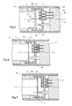
- the conical end 21 of the guide pin 19 enters the orifice 15 of the connection piece 6 and, if necessary, rotates this connecting piece 6 around its axis so as to align the axis of the orifice 15 and the axis of the finger 19 and, consequently, to bring the lugs 12 to 14 opposite the pins 16 to 18, as shown in FIG. figure 5 .
- Pushing is continued on the control device 4 so that the pins 16 to 18 engage in the lugs 12 to 14, as shown in FIG. figure 6 .
- the force of the spring 10 is substantially greater than the force required to introduce the pins in the pods.
- the connecting piece 6 finally comes into abutment against the motor 2, as shown in FIG. figure 6 . The connection is made.
- the control device 4 is not yet fully inserted into the tube 1. It continues to push on the control device 4 until the flange 22 (shown in FIG. figure 1 ) which terminates in abutment against the end B of the tube 1. The further movement of the control device 4 is possible due to the axial play that the connecting piece 6 has with the control device 4. The final position is represented at figure 7 . The connecting piece 6 has moved back relative to the control device 4 by compressing the spring 10.
- the axial clearance makes it possible to ensure in particular an external appearance unit of the actuators and a sealing of the closure of the end B of the tube by the flange 22.
- the axial freedom of the auxiliary connection piece also makes it possible to accept the dispersions inevitable in the axial positioning of the lugs relative to the integral pins of the engine. Indeed, the pins and lugs being in the center of a chain of dimensions including the axial dimensions, the motor, the gearbox, the winding tube and the control device which each have dispersions, it is common that the position Axial of the spindles relative to the pods varies in a range of about 3mm.
- the lugs and pins shown may be replaced by any other pluggable connection means.
- the auxiliary connecting piece could be mounted alternately on the motor instead of being mounted on the control device.
- the connection of the connection piece with one of the elements, motor or control device could be achieved by means other than those shown. It could in particular be mounted friction on a bearing or in a housing of one of the elements, the only requirements to be respected are the angular and axial clearances and a friction force substantially greater than the force required to insert the means of connection of the motor and the control device.
- the angular positioning means could also be made differently.
Landscapes
- Engineering & Computer Science (AREA)
- Power Engineering (AREA)
- Fluid-Damping Devices (AREA)
- Connection Of Motors, Electrical Generators, Mechanical Devices, And The Like (AREA)
- Operating, Guiding And Securing Of Roll- Type Closing Members (AREA)
- Vehicle Body Suspensions (AREA)
- Valve Device For Special Equipments (AREA)
- Lock And Its Accessories (AREA)
- Apparatus For Radiation Diagnosis (AREA)
Description
- L'invention concerne un actionneur électrique tubulaire défini selon le préambule de la revendication 1
- De tels actionneurs, connus sous le nom de moteurs tubulaires, sont utilisés pour manoeuvrer portes, volets, ou stores enroulables.
- Un tel actionneur est plus particulièrement connu du brevet
EP 0 603 119 . La pièce auxiliaire de connexion est constituée ici d'une pièce cylindrique fixée de manière amovible à l'extrémité du moteur devant être reliée au dispositif de commande, cette pièce auxiliaire contenant ou étant entourée d'une certaine longueur de fil prolongeant le bobinage du stator du moteur et portant des cosses auxquelles sont fixées les extrémités de ces fils. Le moteur, plus précisément le moteur et son réducteur sont montés de préférence ensemble par une extrémité du tube, celle qui permet l'application de la force par le réducteur, plus massive, ayant une conformation plus adaptée et occasionnant le plus petit déplacement sous contrainte. La pièce auxiliaire de connexion est ensuite détachée du moteur et ses cosses sont enfichées sur des cosses correspondantes du dispositif de commande avant le montage de celui-ci dans le tube par l'autre extrémité du tube. La réserve de fil bobiné contenu ou porté par la pièce auxiliaire doit donc présenter une longueur suffisante pour que la manipulation puisse se réaliser aisément à l'extérieur du tube. Cette réalisation présente des inconvénients. D'une part, une importante longueur de fil reste libre et flottante à l'intérieur du tube et risque d'être blessée ou pincée. D'autre part, une partie de ce fil est inutile à la fonction de conduction du courant électrique. Un autre inconvénient important est que cette opération de connexion ne peut pas être automatisée. - L'invention a pour but de proposer une structure obviant aux inconvénients de la structure selon l'art antérieur et, en particulier, permettant d'automatiser l'assemblage du moteur et de son dispositif de commande.
- A cet effet, l'actionneur électrique tubulaire selon l'invention est caractérisé par la partie caractérisante de la revendication 1
- La connexion du moteur et de son dispositif de commande est ainsi réalisée automatiquement lors du montage des éléments dans le tube.
- Différents modes de réalisation sont définis par les revendications dépendantes 2 à 4.
- Le dessin annexé représente, à titre d'exemple, un mode d'exécution de l'invention.
- La
figure 1 est une vue en coupe axiale d'un actionneur tubulaire dans lequel le moteur, le réducteur et le dispositif de commande sont représentés très schématiquement. - La
figure 2 est une vue partielle, à plus grande échelle, de la zone de connexion avant connexion. - La
figure 3 est une vue en coupe selon III-III de lafigure 2 . - La
figure 4 est une vue en coupe selon IV-IV de lafigure 2 . - Les
figures 5, 6 et 7 illustrent trois phases successives de la connexion du moteur avec son dispositif de commande. - L'actionneur tubulaire représenté schématiquement à la
figure 1 comprend, de manière connue, un tube cylindrique métallique 1 dans lequel sont montés à force un moteur 2 associé à un réducteur 3 et un dispositif de commande 4 pour le pilotage du moteur 1. Le dispositif de commande 4 peut aller du simple arrêt automatique en fin de course de la charge entraînée par le moteur à des commandes plus évoluées comme un arrêt sur obstacle, un arrêt en position intermédiaire ou la commande selon un programme particulier. De tels dispositifs sont décrits, par exemple, dans les brevetsEP 0 434 614 ,EP 0524 152 ,EP 0 568 492 etEP 0 671 542 . Le réducteur 3 présente un arbre de sortie 5 pour l'entraînement de la charge à actionner, par exemple un store enroulable, un volet roulant ou une porte. Le dispositif de commande 4 est relié électriquement au moteur 2 au moyen d'une pièce auxiliaire de connexion 6 qui sera décrite plus en détail en relation avec lafigure 2 . - La
figure 2 représente l'actionneur avant la connexion du dispositif de commande 4 au moteur 2. La pièce de connexion 6, en matière synthétique, présente une forme de pot cylindrique muni de quatre pattes flexibles 7 prolongeant la paroi cylindrique et réparties sur la circonférence de la pièce 6. Ces pattes 7 se terminent par un crochet et une rampe permettant l'accrochage de la pièce 6 sur l'extrémité du dispositif de commande 4 qui présente à cet effet un col 8 présentant des créneaux 9 dans lesquels viennent s'engager les pattes 7 de la pièce auxiliaire de connexion 6. La longueur des pattes 7 entre leur crochet et leur base est supérieure à l'épaisseur du col 8. Les créneaux 9 s'étendent sur un arc sensiblement supérieur à la largeur des pattes 7, de telle sorte que la pièce de connexion 6 est fixée sur le dispositif de commande 4 avec un jeu angulaire. A l'intérieur de la pièce de connexion 6 est monté un ressort hélicoïdal 10 travaillant en compression entre l'extrémité du dispositif de commande 4 et le fond de la pièce de connexion 6 de manière à pousser cette pièce et maintenir les extrémités en forme de crochet des pattes 7 en butée contre le col 8. L'épaulement 11 visible à lafigure 2 indique le départ des pattes 7. Dans sa partie frontale, la pièce de connexion 6 est munie de trois cosses femelles 12, 13, 14 reliées par des fils non représentés au dispositif de commande 4. Cette même face frontale présente un trou circulaire 15. - De son côté, le moteur 2 est muni de trois broches 16, 17, 18 et d'un doigt 19 s'étendant parallèlement à l'axe 20 du moteur et terminé par un partie conique 21. Lorsque le moteur 2 et le dispositif de commande 4 sont montés dans le tube 1, les axes du trou 15 et du doigt 19 sont à même distance de l'axe 20 du tube 1.
- L'assemblage de l'actionneur sera maintenant décrit au moyen des
figures 2 à 7 . - On introduit tout d'abord à force le moteur 2 et son réducteur 3 dans le tube 1 par l'une des extrémités de ce tube, c'est-à-dire l'extrémité A représentée à la
figure 1 . On présente ensuite le dispositif de commande 4 en face de l'autre extrémité B du tube 1 en orientant celle-ci de façon approximative, par simple repère visuel, la seule contrainte étant que le doigt de guidage 19 du moteur pénètre à coup sûr dans l'orifice correspondant 15 de la pièce auxiliaire de connexion 6. - On engage ensuite le dispositif de commande 4 dans le tube 1. Pendant l'engagement, l'extrémité conique 21 du doigt de guidage 19 pénètre dans l'orifice 15 de la pièce de connexion 6 et fait tourner si nécessaire cette pièce de connexion 6 autour de son axe de manière à aligner l'axe de l'orifice 15 et l'axe du doigt 19 et, par conséquent, à amener les cosses 12 à 14 en face des broches 16 à 18, comme représenté à la
figure 5 . - On continue de pousser sur le dispositif de commande 4 de telle sorte que les broches 16 à 18 s'engagent dans les cosses 12 à 14, comme représenté à la
figure 6 . A cet effet, la force du ressort 10 est sensiblement supérieure à la force qu'il faut pour introduire les broches dans les cosses. La pièce de connexion 6 arrive finalement en butée contre le moteur 2, comme représenté à lafigure 6 . La connexion est réalisée. - Le dispositif de commande 4 n'est toutefois pas encore entièrement introduit dans le tube 1. On continue donc de pousser sur le dispositif de commande 4 jusqu'à ce que la collerette 22 (représentée à la
figure 1 ) qui le termine vienne en butée contre l'extrémité B du tube 1. La poursuite du déplacement du dispositif de commande 4 est possible en raison du jeu axial que la pièce de connexion 6 présente avec le dispositif de commande 4. La position finale est représentée à lafigure 7 . La pièce de connexion 6 a reculé par rapport au dispositif de commande 4 en comprimant le ressort 10. - Le jeu axial permet d'assurer notamment une unité d'aspect extérieur des actionneurs et une étanchéité de la fermeture de l'extrémité B du tube par la collerette 22. La liberté axiale de la pièce auxiliaire de connexion permet aussi d'accepter les dispersions inévitables dans le positionnement axial des cosses par rapport aux broches solidaires du moteur. En effet, les broches et les cosses étant au centre d'une chaîne de cotes comprenant les dimensions axiales, du moteur, du réducteur, du tube d'enroulement et du dispositif de commande qui présentent chacune des dispersions, il est courant que la position axiale des broches par rapport aux cosses varie dans une fourchette d'environ 3mm.
- Les cosses et broches représentées peuvent être remplacées par tout autre moyen de connexion enfichable.
- La pièce auxiliaire de connexion pourrait être montée alternativement sur le moteur au lieu d'être montée sur le dispositif de commande. La solidarisation de la pièce de connexion avec l'un des éléments, moteur ou dispositif de commande, pourrait être réalisée par des moyens autres que ceux représentés. Elle pourrait notamment être montée à frottement sur une portée ou dans un logement de l'un des éléments, les seuls exigences à respecter étant les jeux angulaire et axial et une force de frottement sensiblement supérieure à la force nécessaire à l'enfichage des moyens de connexion du moteur et du dispositif de commande. Les moyens de positionnement angulaires pourraient également être réalisés de manière différente.
Claims (4)
- Actionneur électrique tubulaire comprenant un tube (1) dans lequel sont montés un premier élément comprenant un moteur (2) et un deuxième élément constitué d'un dispositif de commande du moteur (4), ces éléments étant reliés électriquement par une pièce auxiliaire de connexion (6) équipant l'un des éléments et munie de moyens de connexion enfichables (12, 13, 14) reliés électriquement à l'élément sur lequel la pièce auxiliaire de connexion (6) est montée, l'autre élément étant muni de moyens de connexion complémentaires enfichables (16, 17, 18) par lesquels cet élément est connecté aux moyens de connexion (12, 13, 14) de la pièce auxiliaire (6), caractérisé en ce que la pièce auxiliaire de connexion (6) est montée sur l'élément qu'elle équipe avec un jeu angulaire de manière à pouvoir être positionnée angulairement et avec un jeu axial de manière à pouvoir être repoussée par l'autre élément, en ce qu'elle présente des moyens de positionnement angulaire (15) et en ce que l'autre élément présente des moyens de positionnement angulaire (19) coopérant avec les moyens de positionnement angulaire de la pièce auxiliaire de connexion (6) pour le positionnement angulaire de cette pièce auxiliaire (6).
- Actionneur selon la revendication 1, caractérisé en ce que la pièce auxiliaire de connexion (6) est retenue par accrochage sur l'élément qu'elle équipe et en ce qu'un moyen élastique (10) s'oppose à sa poussée par l'autre élément.
- Actionneur selon la revendication 1, caractérisé en ce que la pièce auxiliaire de connexion (6) est montée à frottement sur l'élément qu'elle équipe, la force de frottement étant sensiblement supérieure à la force nécessaire à l'enfichage des moyens de connexion (12, 13, 14, 16, 17, 18) du moteur et du dispositif de commande.
- Actionneur selon l'une des revendications 1 à 3, caractérisé en ce que les moyens de positionnement angulaire sont constitués, d'une part, d'un trou circulaire (15) et, d'autre part, d'un doigt (19) présentant une extrémité conique (21).
Applications Claiming Priority (3)
| Application Number | Priority Date | Filing Date | Title |
|---|---|---|---|
| FR0208025A FR2841702B1 (fr) | 2002-06-27 | 2002-06-27 | Actionneur electrique muni d'une piece de connexion |
| FR0208025 | 2002-06-27 | ||
| PCT/IB2003/002775 WO2004004095A1 (fr) | 2002-06-27 | 2003-06-18 | Actionneur electrique |
Publications (2)
| Publication Number | Publication Date |
|---|---|
| EP1516410A1 EP1516410A1 (fr) | 2005-03-23 |
| EP1516410B1 true EP1516410B1 (fr) | 2011-05-11 |
Family
ID=29724944
Family Applications (1)
| Application Number | Title | Priority Date | Filing Date |
|---|---|---|---|
| EP03761729A Expired - Lifetime EP1516410B1 (fr) | 2002-06-27 | 2003-06-18 | Actionneur electrique |
Country Status (6)
| Country | Link |
|---|---|
| EP (1) | EP1516410B1 (fr) |
| AT (1) | ATE509418T1 (fr) |
| AU (1) | AU2003242909A1 (fr) |
| ES (1) | ES2235680T1 (fr) |
| FR (1) | FR2841702B1 (fr) |
| WO (1) | WO2004004095A1 (fr) |
Cited By (1)
| Publication number | Priority date | Publication date | Assignee | Title |
|---|---|---|---|---|
| EP4571037A1 (fr) | 2023-12-15 | 2025-06-18 | Weinor GmbH & Co. KG | Installation de protection solaire dotée d'une unité de commande fixée au moteur |
Families Citing this family (5)
| Publication number | Priority date | Publication date | Assignee | Title |
|---|---|---|---|---|
| FR2865981B1 (fr) * | 2004-02-06 | 2006-04-21 | Valeo Systemes Dessuyage | Moto-reducteur notamment pour mecanisme d'essuie-glace de vehicule automobile |
| FR2891413B1 (fr) * | 2005-09-28 | 2008-02-08 | Fp2X Groupement D Interet Econ | Dispositif de moteur electrique tubulaire |
| FR2904491B1 (fr) * | 2006-07-31 | 2008-10-17 | Somfy Sas | Procede d'assemblage d'un actionneur tubulaire |
| FR2916011B1 (fr) | 2007-05-10 | 2010-12-10 | Somfy Sas | Actionneur tubulaire d'entrainement d'un ecran et procede de fabrication d'un tel actionneur |
| FR2983368B1 (fr) | 2011-11-24 | 2016-09-02 | Somfy Sas | Actionneur electrique tubulaire d'entrainement pour un ecran domotique, procede d'assemblage d'un tel actionneur et installation comprenant un tel actionneur |
Family Cites Families (4)
| Publication number | Priority date | Publication date | Assignee | Title |
|---|---|---|---|---|
| JP2525661Y2 (ja) * | 1991-12-03 | 1997-02-12 | マブチモーター株式会社 | 玩具用モータの接点構造 |
| FR2699339B1 (fr) * | 1992-12-16 | 1995-02-24 | Somfy | Stator de moteur électrique bobiné. |
| TW351027B (en) * | 1996-04-22 | 1999-01-21 | Seiko Epson Corp | Small motor and the motor drive |
| DE19727202A1 (de) * | 1997-06-26 | 1999-01-28 | Grundfos As | Tauchmotoreinheit |
-
2002
- 2002-06-27 FR FR0208025A patent/FR2841702B1/fr not_active Expired - Fee Related
-
2003
- 2003-06-18 AT AT03761729T patent/ATE509418T1/de not_active IP Right Cessation
- 2003-06-18 ES ES03761729T patent/ES2235680T1/es active Pending
- 2003-06-18 AU AU2003242909A patent/AU2003242909A1/en not_active Abandoned
- 2003-06-18 WO PCT/IB2003/002775 patent/WO2004004095A1/fr not_active Ceased
- 2003-06-18 EP EP03761729A patent/EP1516410B1/fr not_active Expired - Lifetime
Cited By (1)
| Publication number | Priority date | Publication date | Assignee | Title |
|---|---|---|---|---|
| EP4571037A1 (fr) | 2023-12-15 | 2025-06-18 | Weinor GmbH & Co. KG | Installation de protection solaire dotée d'une unité de commande fixée au moteur |
Also Published As
| Publication number | Publication date |
|---|---|
| FR2841702A1 (fr) | 2004-01-02 |
| ES2235680T1 (es) | 2005-07-16 |
| AU2003242909A1 (en) | 2004-01-19 |
| FR2841702B1 (fr) | 2004-09-10 |
| WO2004004095A1 (fr) | 2004-01-08 |
| EP1516410A1 (fr) | 2005-03-23 |
| ATE509418T1 (de) | 2011-05-15 |
Similar Documents
| Publication | Publication Date | Title |
|---|---|---|
| EP0961053B1 (fr) | Motoréducteur notamment pour l'entrainement d'équipements de vehicules | |
| EP2991201B1 (fr) | Dispositif motorisé de manoeuvre destiné à la manoeuvre d'un écran mobile à toile enroulable d'un dispositif de couverture de fenêtre ou d'écran de projection | |
| EP3325754B1 (fr) | Motoréducteur polyvalent pour stores enroulables et stores non enroulables | |
| FR2841613A1 (fr) | Dispositif comportant un cavalier pour la fixation d'une piece sur un panneau | |
| FR2749361A1 (fr) | Reducteur avec accouplement de holdam | |
| EP0829931A1 (fr) | Contacteur tournant à ruban, en particulier pour véhicules automobiles | |
| EP2191093B1 (fr) | Dispositif d'entrainement en rotation et de support d'un tube d'enroulement et installation domotique comprenant un tel dispositif | |
| WO2004004095A1 (fr) | Actionneur electrique | |
| FR3039617B1 (fr) | Boitier de transmission et module de transmission equipe d'un tel boitier | |
| FR2694718A1 (fr) | Tête de coupe pour un dispositif de coupe à fil. | |
| EP3992403A1 (fr) | Actionneur electromecanique pour vehicule automobile | |
| EP0603119B1 (fr) | Stator de moteur électrique bobiné | |
| FR2992367A1 (fr) | Dispositif de demarrage et procede de montage d'un dispositif de demarrage | |
| EP2821584A1 (fr) | Dispositif de manoeuvre d'un équipement de fermeture ou de protection solaire | |
| FR3052933A1 (fr) | Moteur tubulaire pour un systeme d'obturation | |
| EP2061135B1 (fr) | Actionneur tubulaire pour écran domotique et son procédé d'assemblage | |
| FR2917452A1 (fr) | Systeme de liaison entre l'axe d'un volet roulant et une platine supportant l'axe | |
| FR2863016A1 (fr) | Demarreur de vehicule automobile equipe de moyens de centrage du reducteur et de culasse sur le boitier | |
| FR2681911A1 (fr) | Dispositif de butee pour lanceur de demarreur pour moteur a combustion interne et procede pour la mise en óoeuvre d'un tel dispositif. | |
| FR2979126A1 (fr) | Dispositif d'entrainement en rotation, notamment demarreur de moteur thermique et son procede de realisation | |
| EP1283323A1 (fr) | Dispositif d'entraínement de lève-vitre avec des moyens de maintien du tambour dans son boítier | |
| EP0931953A1 (fr) | Dispositif d'entainement avec embrayage à inertie | |
| FR2969686A1 (fr) | Unite d'entrainement et de transmission, element fonctionnel et montage forme de cette unite et de l'element fonctionnel | |
| EP4202173A1 (fr) | Actionneur électromécanique, dispositif d'occultation comprenant un tel actionneur et procédé d'assemblage d'un tel actionneur | |
| EP1020977A1 (fr) | Procédé d'assemblage d'un moteur électrique rotatif |
Legal Events
| Date | Code | Title | Description |
|---|---|---|---|
| PUAI | Public reference made under article 153(3) epc to a published international application that has entered the european phase |
Free format text: ORIGINAL CODE: 0009012 |
|
| 17P | Request for examination filed |
Effective date: 20041130 |
|
| AK | Designated contracting states |
Kind code of ref document: A1 Designated state(s): AT BE BG CH CY CZ DE DK EE ES FI FR GB GR HU IE IT LI LU MC NL PT RO SE SI SK TR |
|
| AX | Request for extension of the european patent |
Extension state: AL LT LV MK |
|
| DAX | Request for extension of the european patent (deleted) | ||
| GRAP | Despatch of communication of intention to grant a patent |
Free format text: ORIGINAL CODE: EPIDOSNIGR1 |
|
| GRAS | Grant fee paid |
Free format text: ORIGINAL CODE: EPIDOSNIGR3 |
|
| GRAA | (expected) grant |
Free format text: ORIGINAL CODE: 0009210 |
|
| AK | Designated contracting states |
Kind code of ref document: B1 Designated state(s): AT BE BG CH CY CZ DE DK EE ES FI FR GB GR HU IE IT LI LU MC NL PT RO SE SI SK TR |
|
| REG | Reference to a national code |
Ref country code: GB Ref legal event code: FG4D Free format text: NOT ENGLISH |
|
| REG | Reference to a national code |
Ref country code: CH Ref legal event code: EP |
|
| REG | Reference to a national code |
Ref country code: IE Ref legal event code: FG4D |
|
| REG | Reference to a national code |
Ref country code: DE Ref legal event code: R096 Ref document number: 60337078 Country of ref document: DE Effective date: 20110622 |
|
| REG | Reference to a national code |
Ref country code: NL Ref legal event code: VDEP Effective date: 20110511 |
|
| PG25 | Lapsed in a contracting state [announced via postgrant information from national office to epo] |
Ref country code: SE Free format text: LAPSE BECAUSE OF FAILURE TO SUBMIT A TRANSLATION OF THE DESCRIPTION OR TO PAY THE FEE WITHIN THE PRESCRIBED TIME-LIMIT Effective date: 20110511 Ref country code: PT Free format text: LAPSE BECAUSE OF FAILURE TO SUBMIT A TRANSLATION OF THE DESCRIPTION OR TO PAY THE FEE WITHIN THE PRESCRIBED TIME-LIMIT Effective date: 20110912 |
|
| PG25 | Lapsed in a contracting state [announced via postgrant information from national office to epo] |
Ref country code: SI Free format text: LAPSE BECAUSE OF FAILURE TO SUBMIT A TRANSLATION OF THE DESCRIPTION OR TO PAY THE FEE WITHIN THE PRESCRIBED TIME-LIMIT Effective date: 20110511 Ref country code: AT Free format text: LAPSE BECAUSE OF FAILURE TO SUBMIT A TRANSLATION OF THE DESCRIPTION OR TO PAY THE FEE WITHIN THE PRESCRIBED TIME-LIMIT Effective date: 20110511 Ref country code: CY Free format text: LAPSE BECAUSE OF FAILURE TO SUBMIT A TRANSLATION OF THE DESCRIPTION OR TO PAY THE FEE WITHIN THE PRESCRIBED TIME-LIMIT Effective date: 20110511 Ref country code: FI Free format text: LAPSE BECAUSE OF FAILURE TO SUBMIT A TRANSLATION OF THE DESCRIPTION OR TO PAY THE FEE WITHIN THE PRESCRIBED TIME-LIMIT Effective date: 20110511 Ref country code: GR Free format text: LAPSE BECAUSE OF FAILURE TO SUBMIT A TRANSLATION OF THE DESCRIPTION OR TO PAY THE FEE WITHIN THE PRESCRIBED TIME-LIMIT Effective date: 20110812 |
|
| REG | Reference to a national code |
Ref country code: IE Ref legal event code: FD4D |
|
| PG25 | Lapsed in a contracting state [announced via postgrant information from national office to epo] |
Ref country code: NL Free format text: LAPSE BECAUSE OF FAILURE TO SUBMIT A TRANSLATION OF THE DESCRIPTION OR TO PAY THE FEE WITHIN THE PRESCRIBED TIME-LIMIT Effective date: 20110511 |
|
| BERE | Be: lapsed |
Owner name: SOMFY SAS Effective date: 20110630 |
|
| PG25 | Lapsed in a contracting state [announced via postgrant information from national office to epo] |
Ref country code: CZ Free format text: LAPSE BECAUSE OF FAILURE TO SUBMIT A TRANSLATION OF THE DESCRIPTION OR TO PAY THE FEE WITHIN THE PRESCRIBED TIME-LIMIT Effective date: 20110511 Ref country code: IE Free format text: LAPSE BECAUSE OF FAILURE TO SUBMIT A TRANSLATION OF THE DESCRIPTION OR TO PAY THE FEE WITHIN THE PRESCRIBED TIME-LIMIT Effective date: 20110511 Ref country code: EE Free format text: LAPSE BECAUSE OF FAILURE TO SUBMIT A TRANSLATION OF THE DESCRIPTION OR TO PAY THE FEE WITHIN THE PRESCRIBED TIME-LIMIT Effective date: 20110511 |
|
| REG | Reference to a national code |
Ref country code: CH Ref legal event code: PL |
|
| PG25 | Lapsed in a contracting state [announced via postgrant information from national office to epo] |
Ref country code: RO Free format text: LAPSE BECAUSE OF FAILURE TO SUBMIT A TRANSLATION OF THE DESCRIPTION OR TO PAY THE FEE WITHIN THE PRESCRIBED TIME-LIMIT Effective date: 20110511 Ref country code: SK Free format text: LAPSE BECAUSE OF FAILURE TO SUBMIT A TRANSLATION OF THE DESCRIPTION OR TO PAY THE FEE WITHIN THE PRESCRIBED TIME-LIMIT Effective date: 20110511 Ref country code: DK Free format text: LAPSE BECAUSE OF FAILURE TO SUBMIT A TRANSLATION OF THE DESCRIPTION OR TO PAY THE FEE WITHIN THE PRESCRIBED TIME-LIMIT Effective date: 20110511 |
|
| PLBE | No opposition filed within time limit |
Free format text: ORIGINAL CODE: 0009261 |
|
| STAA | Information on the status of an ep patent application or granted ep patent |
Free format text: STATUS: NO OPPOSITION FILED WITHIN TIME LIMIT |
|
| PG25 | Lapsed in a contracting state [announced via postgrant information from national office to epo] |
Ref country code: BE Free format text: LAPSE BECAUSE OF NON-PAYMENT OF DUE FEES Effective date: 20110630 |
|
| 26N | No opposition filed |
Effective date: 20120214 |
|
| GBPC | Gb: european patent ceased through non-payment of renewal fee |
Effective date: 20110811 |
|
| PG25 | Lapsed in a contracting state [announced via postgrant information from national office to epo] |
Ref country code: LI Free format text: LAPSE BECAUSE OF NON-PAYMENT OF DUE FEES Effective date: 20110630 Ref country code: CH Free format text: LAPSE BECAUSE OF NON-PAYMENT OF DUE FEES Effective date: 20110630 |
|
| REG | Reference to a national code |
Ref country code: DE Ref legal event code: R097 Ref document number: 60337078 Country of ref document: DE Effective date: 20120214 |
|
| PG25 | Lapsed in a contracting state [announced via postgrant information from national office to epo] |
Ref country code: GB Free format text: LAPSE BECAUSE OF NON-PAYMENT OF DUE FEES Effective date: 20110811 |
|
| PG25 | Lapsed in a contracting state [announced via postgrant information from national office to epo] |
Ref country code: MC Free format text: LAPSE BECAUSE OF NON-PAYMENT OF DUE FEES Effective date: 20110630 Ref country code: ES Free format text: LAPSE BECAUSE OF FAILURE TO SUBMIT A TRANSLATION OF THE DESCRIPTION OR TO PAY THE FEE WITHIN THE PRESCRIBED TIME-LIMIT Effective date: 20110822 |
|
| PG25 | Lapsed in a contracting state [announced via postgrant information from national office to epo] |
Ref country code: LU Free format text: LAPSE BECAUSE OF NON-PAYMENT OF DUE FEES Effective date: 20110618 |
|
| PG25 | Lapsed in a contracting state [announced via postgrant information from national office to epo] |
Ref country code: BG Free format text: LAPSE BECAUSE OF FAILURE TO SUBMIT A TRANSLATION OF THE DESCRIPTION OR TO PAY THE FEE WITHIN THE PRESCRIBED TIME-LIMIT Effective date: 20110811 |
|
| PG25 | Lapsed in a contracting state [announced via postgrant information from national office to epo] |
Ref country code: TR Free format text: LAPSE BECAUSE OF FAILURE TO SUBMIT A TRANSLATION OF THE DESCRIPTION OR TO PAY THE FEE WITHIN THE PRESCRIBED TIME-LIMIT Effective date: 20110511 |
|
| PG25 | Lapsed in a contracting state [announced via postgrant information from national office to epo] |
Ref country code: HU Free format text: LAPSE BECAUSE OF FAILURE TO SUBMIT A TRANSLATION OF THE DESCRIPTION OR TO PAY THE FEE WITHIN THE PRESCRIBED TIME-LIMIT Effective date: 20110511 |
|
| REG | Reference to a national code |
Ref country code: FR Ref legal event code: PLFP Year of fee payment: 14 |
|
| PGFP | Annual fee paid to national office [announced via postgrant information from national office to epo] |
Ref country code: DE Payment date: 20160525 Year of fee payment: 14 |
|
| PGFP | Annual fee paid to national office [announced via postgrant information from national office to epo] |
Ref country code: FR Payment date: 20160607 Year of fee payment: 14 |
|
| PGFP | Annual fee paid to national office [announced via postgrant information from national office to epo] |
Ref country code: IT Payment date: 20160620 Year of fee payment: 14 |
|
| REG | Reference to a national code |
Ref country code: DE Ref legal event code: R119 Ref document number: 60337078 Country of ref document: DE |
|
| REG | Reference to a national code |
Ref country code: FR Ref legal event code: ST Effective date: 20180228 |
|
| PG25 | Lapsed in a contracting state [announced via postgrant information from national office to epo] |
Ref country code: DE Free format text: LAPSE BECAUSE OF NON-PAYMENT OF DUE FEES Effective date: 20180103 |
|
| PG25 | Lapsed in a contracting state [announced via postgrant information from national office to epo] |
Ref country code: FR Free format text: LAPSE BECAUSE OF NON-PAYMENT OF DUE FEES Effective date: 20170630 Ref country code: IT Free format text: LAPSE BECAUSE OF NON-PAYMENT OF DUE FEES Effective date: 20170618 |