EP1516214B1 - Vorrichtung und verfahren zum spalten dünner stäbe - Google Patents
Vorrichtung und verfahren zum spalten dünner stäbe Download PDFInfo
- Publication number
- EP1516214B1 EP1516214B1 EP03738821A EP03738821A EP1516214B1 EP 1516214 B1 EP1516214 B1 EP 1516214B1 EP 03738821 A EP03738821 A EP 03738821A EP 03738821 A EP03738821 A EP 03738821A EP 1516214 B1 EP1516214 B1 EP 1516214B1
- Authority
- EP
- European Patent Office
- Prior art keywords
- rod
- clamping
- blade
- cleaving
- fibre
- Prior art date
- Legal status (The legal status is an assumption and is not a legal conclusion. Google has not performed a legal analysis and makes no representation as to the accuracy of the status listed.)
- Expired - Lifetime
Links
- 238000000034 method Methods 0.000 title claims abstract description 24
- 239000000463 material Substances 0.000 claims abstract description 13
- VYPSYNLAJGMNEJ-UHFFFAOYSA-N silicon dioxide Inorganic materials O=[Si]=O VYPSYNLAJGMNEJ-UHFFFAOYSA-N 0.000 claims abstract description 10
- 239000010453 quartz Substances 0.000 claims abstract description 8
- 239000011521 glass Substances 0.000 claims abstract description 7
- 239000000835 fiber Substances 0.000 claims description 112
- 230000009471 action Effects 0.000 claims description 10
- 230000003287 optical effect Effects 0.000 claims description 7
- 238000005452 bending Methods 0.000 claims description 5
- 238000004590 computer program Methods 0.000 claims description 5
- 238000005520 cutting process Methods 0.000 claims description 5
- 235000019788 craving Nutrition 0.000 claims 1
- 230000008569 process Effects 0.000 description 6
- 230000008901 benefit Effects 0.000 description 5
- 230000000694 effects Effects 0.000 description 5
- 239000013307 optical fiber Substances 0.000 description 5
- 238000010276 construction Methods 0.000 description 3
- 230000010355 oscillation Effects 0.000 description 3
- 230000002393 scratching effect Effects 0.000 description 3
- 230000001419 dependent effect Effects 0.000 description 2
- 239000010432 diamond Substances 0.000 description 2
- 229910003460 diamond Inorganic materials 0.000 description 2
- 230000003116 impacting effect Effects 0.000 description 2
- 238000005304 joining Methods 0.000 description 2
- 230000000284 resting effect Effects 0.000 description 2
- 238000006748 scratching Methods 0.000 description 2
- 230000008859 change Effects 0.000 description 1
- 238000012512 characterization method Methods 0.000 description 1
- 238000005253 cladding Methods 0.000 description 1
- 230000003247 decreasing effect Effects 0.000 description 1
- 230000005684 electric field Effects 0.000 description 1
- 239000002305 electric material Substances 0.000 description 1
- 238000002474 experimental method Methods 0.000 description 1
- 230000002349 favourable effect Effects 0.000 description 1
- 238000004519 manufacturing process Methods 0.000 description 1
- 238000012986 modification Methods 0.000 description 1
- 230000004048 modification Effects 0.000 description 1
- 239000000377 silicon dioxide Substances 0.000 description 1
Images


Classifications
-
- G—PHYSICS
- G02—OPTICS
- G02B—OPTICAL ELEMENTS, SYSTEMS OR APPARATUS
- G02B6/00—Light guides; Structural details of arrangements comprising light guides and other optical elements, e.g. couplings
- G02B6/24—Coupling light guides
- G02B6/25—Preparing the ends of light guides for coupling, e.g. cutting
-
- Y—GENERAL TAGGING OF NEW TECHNOLOGICAL DEVELOPMENTS; GENERAL TAGGING OF CROSS-SECTIONAL TECHNOLOGIES SPANNING OVER SEVERAL SECTIONS OF THE IPC; TECHNICAL SUBJECTS COVERED BY FORMER USPC CROSS-REFERENCE ART COLLECTIONS [XRACs] AND DIGESTS
- Y10—TECHNICAL SUBJECTS COVERED BY FORMER USPC
- Y10T—TECHNICAL SUBJECTS COVERED BY FORMER US CLASSIFICATION
- Y10T225/00—Severing by tearing or breaking
- Y10T225/10—Methods
-
- Y—GENERAL TAGGING OF NEW TECHNOLOGICAL DEVELOPMENTS; GENERAL TAGGING OF CROSS-SECTIONAL TECHNOLOGIES SPANNING OVER SEVERAL SECTIONS OF THE IPC; TECHNICAL SUBJECTS COVERED BY FORMER USPC CROSS-REFERENCE ART COLLECTIONS [XRACs] AND DIGESTS
- Y10—TECHNICAL SUBJECTS COVERED BY FORMER USPC
- Y10T—TECHNICAL SUBJECTS COVERED BY FORMER US CLASSIFICATION
- Y10T225/00—Severing by tearing or breaking
- Y10T225/30—Breaking or tearing apparatus
- Y10T225/371—Movable breaking tool
- Y10T225/379—Breaking tool intermediate spaced work supports
- Y10T225/386—Clamping supports
-
- Y—GENERAL TAGGING OF NEW TECHNOLOGICAL DEVELOPMENTS; GENERAL TAGGING OF CROSS-SECTIONAL TECHNOLOGIES SPANNING OVER SEVERAL SECTIONS OF THE IPC; TECHNICAL SUBJECTS COVERED BY FORMER USPC CROSS-REFERENCE ART COLLECTIONS [XRACs] AND DIGESTS
- Y10—TECHNICAL SUBJECTS COVERED BY FORMER USPC
- Y10T—TECHNICAL SUBJECTS COVERED BY FORMER US CLASSIFICATION
- Y10T83/00—Cutting
- Y10T83/04—Processes
Definitions
- the present invention relates to an apparatus for cleaving thin rods of glass or quartz (silica) having a diameter below 1 mm as well as a method for carrying out such a cleaving according to the preambles of the appended independent apparatus and method claims.
- the invention is in general directed to cleaving such thin rods of glass or quartz for any subsequent use, the invention is particularly directed to cleaving such thin rods of quartz in the form of optical fibres.
- the invention and the problem to be solved thereby will therefor hereinafter by way of example be discussed for cleaving such optical fibres without limiting the scope of the invention.
- Optical fibre ends are commonly prepared for a variety of purposes (jointing, characterization etc) by a process known as cleaving.
- a blade prepared from a hard material, such a diamond is brought into a lateral engagement with the fibre to be cleaved in such a manner as to initiate a fracture which subsequently propagates through the fibre cross-section until the fibre parts.
- the resulting cleaved fibre end surface should, as far as possible, be optically flat and perpendicular to the fibre longitudinal axis. Undue intrusion of the blade into the fibre during the cleaving process can damage the fibre so as to detract from the quality of the resulting end surfaces.
- the apparatus according to said US-patent needs frequencies above 1 kHz for said vibratory component of movement, and in fact frequencies above 20 kHz are used there.
- the apparatus of US-patent 4 790 465 may be used for obtaining comparatively high quality cleaved fibre end surfaces there is of course always a desire to improve such an apparatus with respect to both the cleaving result and the construction and by that the costs for manufacture and operation thereof.
- the object of the present invention is to provide an apparatus of the type defined in the introduction being improved in at least some aspect with respect to such apparatuses already known.
- said driving means is adapted to make the blade vibrate with a frequency between 100 and 700 Hz or between 250 and 450 Hz. It has been found that frequencies coming close to 1 000 Hz give rise to resonance effects in said body of said material, and it is necessary to keep the frequency well below such a resonance frequency. is preferred that the frequency is well below the resonance frequency and for some embodiments below 450 Hz. Although the US-patent mentioned above indicates that it shouldn't be possible to cleave rods of this type while using frequencies below 1 kHz, it has surprisingly been found that much lower frequencies may be used with a maintained and even improved cleaving result.
- the apparatus is adapted to cleave optical fibres and to cleave rods having a diameter below 600 ⁇ m or below 300 ⁇ m and preferably between 50 and 200 ⁇ m, which are typical dimensions of the cross section of an optical fibre including the core and the cladding.
- the piezo-electrical effect or the magneto-strictive effect are used for obtaining the two superimposed movements of the blade.
- the blade is arranged on a free end of a said body in the form of a strip-like stave being fixed at the other end, and said driving means is adapted to cause said movements through bending the strip-like stave towards said desired cleaving point of the rod so that said movements of the blade take place along an arc-like path and the blade will hit the fibre in a direction making an angle with the fibre differing from 90° for cutting the fibre in this direction. It has turned out that the movements of the free end of such a strip-like stave and by that of the blade may be controlled very accurately for obtaining a cleaving result with excellent properties when using the piezo-electric or magneto-strictive effect in combination with the low frequencies mentioned above.
- the blade will also "scratch" the fibre when hitting it resulting in a cleaner score and fibre end surface than when just impacting the fibre perpendicularly thereto as in said US-patent 4 790 465 .
- This action is further improved by arranging the blade on the free end of a projection projecting from the stave towards the fibre at a distance from the stave.
- said arrangement comprises a first clamping means arranged to clamp said rod in a first said clamping location, said first clamping means has a first clamping member with a clamp face of substantially V-groove type, for receiving the rod in the groove, and a second clamping member having a flat opposing clamp face for retaining the rod in the groove, and the first clamping member having the groove clamped face is moveable towards and away from the second clamping member for clamping and releasing a said rod.
- the first clamping member is received in a guide and removable from the apparatus by pushing or lifting it out of the guide for exchange.
- Such an arrangement of the first clamping member having the grooved clamp face means that this clamping member may be removed and exchanged very easily and rapidly and without any problem to maintain a high accuracy of the clamping action.
- said arrangement comprises a second clamping means arranged to clamp said rod in a second said clamping location, the second clamping means is movable in the longitudinal direction of a said rod extended between the two clamping locations, the apparatus comprises means for moving the second clamping means in said longitudinal direction for extending a rod clamped by said arrangement for applying a longitudinal tension load to the rod, and the second clamping means is adapted to clamp said rod in a second said clamping location belonging to the part of a cleaved rod intended for later use.
- Such an embodiment is particularly advantageous in the case of having an apparatus with a body carrying the blade and driving means adapted to act upon said body for causing a relatively steady movement of the blade towards said desired cleaving point while subjecting the blade to a relatively small-amplitude vibratory component of movement towards and away from said cleaving point superimposed to said relatively steady movement towards the cleaving point, since this then means that there will be no risk that the vibrating blade will hit the rod once again after the rod has been cleaved.
- the apparatus further comprises at least one member having at least one inclined surface and means for moving said member laterally towards a rod being clamped in only one of said two clamping locations before clamping it in the other clamping location with the inclined surface into abutment against the rod for influencing the rod by sliding thereof upon said surface for reaching the position desired for said other clamping location before clamping the rod in that location.
- the existence of such a member moving the rod into the desired position before the rod is clamped in said other clamping location means that the clamping action may be carried out while reducing the risk of twisting the rod by said clamping action, which would degrade the quality of the future cleaved end surface.
- the invention also relates to a method of cleaving a thin rod according to the appended independent method claim.
- the advantages of such a method and the embodiments thereof according to the appended dependent method claims appear without any doubt from the above discussion of the preferred embodiments of the apparatus according to the present invention.
- the invention also relates to a computer program and a computer readable medium according to the corresponding appended claims. It is easily understood that the method according to the invention defined in the appended set of method claims is well suited to be carried out through instructions from a processor that may be influenced by a computer program provided with the program steps in question.
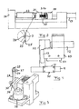
- Fig 1 illustrates an apparatus for cleaving thin rods of glass or quartz, preferably optical fibres, having a diameter below 1 mm, and preferably in the range of 50 ⁇ m - 200 ⁇ m.
- the optical fibre is clamped in a second clamping means 1 in the form of a conventional fibre holder used for holding a fibre also when joining two optical fibres, and this is already known. It is schematically illustrated in fig 2 by dashed lines how a lid 2 of said clamping means may be pivoted for opening and closing this clamping means.
- This clamping means 1 is adapted to hold the fibre to be cleaved with a part 3 on which the cleaving is to be carried out projecting out from the fibre holder.
- the apparatus also comprises a member 4 adapted to receive the fibre holder 1 therein for holding it in a well-defined position during the cleaving sequence.
- the receiving member 4 has the character of a carriage with a bottom 5 onto which the fibre holder is intended to rest and guiding members 6 in the form of pins for laterally supporting the fibre holder in a well defined position on the carriage 4.
- the carriage has also a front member 7 extending upwardly from the bottom 5 and defining the position of the fibre holder in the longitudinal direction of a fibre held therein.
- This front member 7 has a central slot 8 extending therethrough and opening upwardly for receiving the free fibre part 3 therein.
- the carriage 4 is moveable in the longitudinal direction of a fibre in a fibre holder received therein and in the longitudinal direction of a rail 9 in a way to be described further below.
- This construction of said receiving member 4 is very favourable with respect to the loading of a fibre to be cleaved in the apparatus.
- This loading action takes place in the following way.
- the fibre holder 1 with a fibre clamped therein and a part 3 to be cleaved projecting out therefrom is placed in the position shown in fig 1 with the front portions of the fibre holder 1 resting upon the upper surfaces 10 of the front member 7.
- the guiding pins 6 will define the correct direction of the fibre holder.
- the fibre holder 1 is then retracted, so that it will leave the support on the front member 7 and be lowered onto the bottom 5 of the receiving member 4 while being guided in a well defined movement through the guiding pins 6, and the part 3 of the fibre will move down in the slot 8 to the position shown in fig 2 .
- This well controlled movement of the fibre part 3 means that there is no risk of damaging the fibre through contact with other members of the apparatus during this loading action.
- the front member 7 and the bottom 5 of the carriage 4 are adapted to magnetically interact with the fibre holder 1 having for this sake magnets for keeping the fibre holder in a well defined position with the front end 11 1 thereof into contact with the front member 7.
- the apparatus also comprises a member 14 adapted to adjust the position of the fibre part 3 in another of said two clamping locations thereof before the fibre is clamped in that location.
- This member 14 comprises for that sake two members 15 extending substantially in parallel with each other from a frame 16 and having each two inclined surfaces 17, 18, which are oppositely inclined with respect to a horizontal plane through the two clamping locations desired.
- Driving means 19, here driven by compressed air, is arranged to move the member 14 so that the fibre part 3 comes into abutment against one of the inclined surfaces of each member 15 for sliding thereupon and reaching the position desired for a clamping location of the fibre part 3 corresponding to a position of the fibre part in a seat of the members 15 in the intersection between the two inclined surfaces 17, 18 of each member 15.
- This means that the fibre part 3 is then in a well-defined position before it is clamped, so that it may be subsequently clamped without being damaged or exerted to torsion loads or the like.
- a spring member 20 is counter-acting the driving means 19 while being arranged to act between a member 21 being fixed with respect to a frame work of the apparatus and the frame 16 of the member 14, so that the member 14 will automatically be withdrawn from the fibre part when the influence of the driving means 19 thereupon is removed.
- the apparatus also comprises a first clamping means adapted to clamp the fibre in one of said two mutually-spaced clamping locations, and this first clamping means comprises a first clamping member 22 with a clamp face 23 of substantially V-groove type, for receiving a fibre part 3 in a groove 24, and a second clamping member formed by said fixed member 21 having a flat opposing clamp face 25 for retaining the fibre in the groove.
- the apparatus comprises a driving means 26 driven by compressed air for moving said first clamping member 22 in the direction towards the second clamping member 21 for clamping a fibre.
- the first clamping member 22 is constituted by a block-like piece resting only by means of the gravitation on a surface in a guide, so that it may easily be removed from the apparatus by lifting it out of the guide for exchange when the groove or the face portions adjacent thereto have been worn out or for replacing it by a first clamping member being designed for clamping rods with a different diameter.
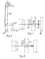
- the apparatus also comprises a rod cleaving blade 27 (see especially figs 5 and 6 ) adapted to be brought into lateral contact with the fibre at the desired cleaving point between said two clamping locations, to achieve cleaving of the fibre at said point.
- This blade 27 is made of a hard material, such as diamond.
- the cleaving blade is carried by a body 28 comprising a strip-like stave having the blade 27 arranged on a free end 29 thereof and being fixed at the other end 30.
- This stave is made of a material varying its length through application of an electric field therein, i.e. a piezo-electric material.
- the apparatus further comprises driving means adapted to act upon the stave for causing a relatively steady movement of the blade towards a desired cleaving point while subjecting the blade to a relatively small-amplitude vibratory component of movement towards and away from said cleaving point superimposed to said relatively steady movement towards the cleaving point.
- driving means adapted to act upon the stave for causing a relatively steady movement of the blade towards a desired cleaving point while subjecting the blade to a relatively small-amplitude vibratory component of movement towards and away from said cleaving point superimposed to said relatively steady movement towards the cleaving point.
- this path of these movements means that the blade will "scratch" the fibre when hitting it resulting in a cleaner score and fibre end surface than when just impacting the fibre perpendicularly thereto as in said US-patent 4 790 465 .
- This scratching action is further improved by arranging the blade on the free end of a projection 54 projecting from the stave towards the fibre at a distance from the stave.
- the movements are achieved in the way illustrated in fig 6 by applying a direct voltage through a direct voltage source 31 across the stave 28, the magnitude of which is controlled by a control means 32 for bending the free end of the stave 28 towards a fibre clamped in the apparatus.
- the driving means also comprises an alternating voltage source 33 adapted to apply an alternating voltage across the stave 28 for generating said vibratory component of movement of the blade. Also the alternating voltage source is controlled by the control means 32.
- the alternating voltage applied to the stave has a frequency below 1 kHz and preferably below 750 Hz. In a particular embodiment the frequency is about 350 Hz.
- the peak to peak voltage of the alternating voltage may typically be in the order of 50 V, whereas the direct voltage may typically be varied from 0 to 100 V.
- the stave 28 is fixed to a frame 34 moveable with respect to the frame work of the apparatus through a step motor 35 in the vertical direction in steps of for example 50 ⁇ m for controlling the position along the blade of the blade portion used for cleaving a fibre, so that this position may be changed for changing said blade portion when a previous blade portion has been worn out, for example after carrying out about 1 000 cleaving operations while using the same blade portion therefor.
- This is preferably controlled by a computer program.
- the fibre holder 1 is firstly arranged in the carriage 4 in the way indicated in fig 1 and in the position shown in fig 2 .
- a button is then pressed and the rest of the operation of the apparatus will take place automatically and preferably controlled by a computer 40 indicated in Fig 2 .
- the dc-motor 12 will firstly move the carriage 4 so that the free end 36 of the fibre comes inside a small tube 37 belonging to a device 38 adapted to draw a waist fibre portion 39 away through application of negative air pressure after the cleaving has been performed.
- the driving means 19 moves the members 15 towards the fibre for entering contact therewith through the inclined surfaces 17, 18 for adjusting the height of the fibre.
- the driving means 26 is then pushing the first clamping member 22 of the first clamping means towards the fixed clamping member 21 for clamping the fibre in a first clamping location mutually-spaced from the second clamping location defined by the fibre holder 1.
- the action of the driving means 19 upon the member 14 is then removed, so that this member 14 is retracted through the action of the spring member 20.
- Said computer indicated through the dashed box 40 is then sending a signal to the means 12 for influencing the carriage 4 in the longitudinal direction of the fibre away from the second clamping location for applying a tension load to the fibre.
- the magnitude of this tension load is measured through the load cell 13 sending information thereabout to the computer 40.
- the tension load is in this way set to a value by the computer, for instance 1,5 N, but this value will change with the diameter of the fibre or the rod to be cleaved.
- the driving means 35 is then controlled to move the blade 27 vertically to the desired position for the cleaving procedure.
- the control unit 32 does then control the direct voltage source 31 to gradually increase the direct voltage applied to the stave 28 for bending the stave, so that the blade 27 carries out a relatively steady movement towards the fibre.
- the control unit 32 controls at the same time the alternating voltage source 33 to apply an alternating voltage to the stave 28 for causing the blade 27 to vibrate towards and away from the fibre with a small amplitude in the order of 5-40 ⁇ m, preferably in the range of 30 ⁇ m.
- the blade 27 will in this way move with a velocity in the order of 1 mm/s towards the fibre while oscillating for cleaving the fibre.
- the low frequency of the vibration means that the blade 27 will move comparatively far in the direction towards the fibre in the period of time between two subsequent oscillations at a given suitable velocity of said relatively steady movement.
- this velocity is 1 mm/s and said frequency is 400 Hz this means an advancing distance of 2,5 ⁇ m between subsequent "strikes” or “cuts” of the blade, which is much more than for the blade in the US-patent discussed in the introduction.
- This is a great advantage, since it means that the probability that the fibre parts already after being hit once by the blade is high and the fibre end surface resulting from the cleaving would be degraded by additional hits by the blade.
- This low frequency effect is particularly advantageous in combination with the type of movement path described by the blade in the embodiment of the invention illustrated in the figures.
- the height position of the blade will be lowered by about 250 ⁇ m. This means that the blade in average sinks 0,5 ⁇ m for each 1 ⁇ m of advance.
- the intrusion of the blade into the fibre may be about 2 ⁇ m. If the fibre is displaced 3 ⁇ m before the blade penetrates into the fibre the blade is in contact with the fibre over a distance of 5 ⁇ m while moving downwardly by 2,5 ⁇ m in a cutting, scratching movement. In fact, the blade will move even longer, >3 ⁇ m, downwardly when scratching the fibre as a consequence of an increase of this component of the movement direction the closer the blade comes the fibre.
- the load cell 13 will indicate that the fibre has been cleaved through the disappearing of the tension load in the fibre. This information from the load cell will cause the control means 32 to stop the oscillation of the blade and remove the bending action thereupon. Furthermore, the spring force in the load cell will automatically move the cleaved fibre end away from the blade immediately when the fibre parts.
- the motor 12 is then controlled to move the carriage 4 slightly, in the order of 1 mm, away from the cleaving point for removing the cleaved end surface from the cleaving point as shown in fig 7 .
- the driving means 19 is then controlled to move the member 14 to the position shown in fig 7 in contact with the waist fibre portion 39 resulting from the cleaving.
- the control means 32 influences then the direct voltage source 31 to move the blade 27 towards the waist fibre portion to laterally apply a force thereonto as shown in fig 7 .
- the driving means 26 is then controlled to move the first clamping member 22 of the first clamping means away from the second clamping member 21 for releasing the waist fibre portion, and the tension caused therein by the blade will assist the waist fibre portion to leave the groove 24 and be drawn away through the tube 37 by the device 38 for being disposed of.
- the member 14 is retracted by shutting-off the pressurized air to the means 19, so that the spring 20 pushes the member 14 back.
- the control means 32 controls a withdrawal of the blade and the motor 35 returns the blade to the start position.
- the fibre holder 1 may now be removed for using the fibre end surface obtained through the cleaving process for joining or other purposes.
- the carriage 4 is moved to the "home" position by means of the dc-motor 12. The apparatus is now ready for cleaving a new fibre.
- the material of the body carrying the blade may just as well be of the type varying its length through application of magnetic fields, i.e. which has magneto-strictive properties, so that a relatively steady varying magnetic field and an alternating magnetic field may be used for generating the two superimposed movements of the blade according to the present invention.
- the guiding pins for laterally supporting the fibre holder may be replaced by any suitable guiding members, such as lateral guiding walls.
- the member having at least one inclined surface for guiding the rod into said groove may just as well be arranged on the first clamping member laterally thereof for being moved together therewith so that the same driving means may be used for these two members.
Landscapes
- Physics & Mathematics (AREA)
- General Physics & Mathematics (AREA)
- Optics & Photonics (AREA)
- Re-Forming, After-Treatment, Cutting And Transporting Of Glass Products (AREA)
- Perforating, Stamping-Out Or Severing By Means Other Than Cutting (AREA)
- Manufacturing Of Tubular Articles Or Embedded Moulded Articles (AREA)
- Mechanical Treatment Of Semiconductor (AREA)
Claims (29)
- Vorrichtung zum Spalten dünner Stäbe (3) aus Glas oder Quarz mit einem Durchmesser von unter 1 mm, umfassend:- eine Anordnung, die zwei in Abstand zueinander stehende Einspannstellen zum Halten des zwischen den beiden Einspannstellen eingespannten Stabs definiert,- eine Stabspaltklinge (27), die geeignet ist, mit einem solchen Stab an einem gewünschten Spaltpunkt zwischen den beiden Einspannstellen in einen Seitenkontakt gebracht zu werden, um das Spalten des Stabes an dem Punkt zu erreichen,- einen Körper (28), der die Klinge trägt,- Antriebsmittel (31, 33), die geeignet sind, auf den Körper einzuwirken, um eine relativ gleichförmige Bewegung der Klinge zu dem gewünschten Spaltpunkt zu bewirken, während die Klinge einer relativ kleinamplitudig schwingenden Bewegungskomponente zu dem Spaltpunkt hin und von ihm weg ausgesetzt wird, die auf die relativ gleichförmige Bewegung zu dem Spaltpunkt hin aufgebracht wird,wobei der Körper (28) aus einem Material hergestellt ist, dessen Länge durch das Anlegen elektrischer und/oder magnetischer Felder darin veränderlich ist, wobei das Antriebsmittel geeignet ist, die Bewegungen der Klinge durch elektrisches und/oder magnetisches Beeinflussen des Körpers zu erreichen, um Längenveränderungen seines Materials zu erzeugen, dadurch gekennzeichnet, dass das Antriebsmittel geeignet ist, den Körper und somit die Klinge mit einer relativ kleinamplitudigen Komponente, die eine Frequenz von unter 750 Hz hat, zu dem Spaltpunkt hin und von ihm weg in Schwingung zu versetzen, um den Stab zu spalten.
- Vorrichtung nach Anspruch 1, dadurch gekennzeichnet, dass das Antriebsmittel (33) geeignet ist, die Klinge mit einer Frequenz von 100 bis 700 Hz oder von 250 bis 450 Hz in Schwingung zu versetzen.
- Vorrichtung nach Anspruch 1 oder 2, dadurch gekennzeichnet, dass sie geeignet ist, optische Fasern zu spalten.
- Vorrichtung nach einem der Ansprüche 1 bis 3, dadurch gekennzeichnet, dass sie geeignet ist, die Stäbe mit einem Durchmesser von unter 600 µm oder unter 300 µm, und vorzugsweise zwischen 50 und 200 µm, zu spalten.
- Vorrichtung nach einem der vorhergehenden Ansprüche, dadurch gekennzeichnet, dass das Material des Körpers (28) piezoelektrische Eigenschaften aufweist, dass das Antriebsmittel (31, 33) geeignet ist, eine relativ gleichförmig variierende Gleichspannung an den Körper anzulegen, um die relativ gleichförmige Bewegung der Klinge zu erhalten, und eine Wechselspannung an den Körper anzulegen, um die relativ kleinamplitudige Schwingungskomponente der Bewegung der Klinge zu erhalten, und dass die Vorrichtung ferner ein Steuerungsmittel (32) zum Steuern mindestens der Höhe der relativ gleichförmig variierenden Gleichspannung umfasst.
- Vorrichtung nach einem der Ansprüche 1 bis 4, dadurch gekennzeichnet, dass das Material des Körpers (28) magnetostriktive Eigenschaften aufweist, dass das Antriebmittel geeignet ist, ein relativ gleichförmig variierendes Magnetfeld in dem Material anzulegen, um die relativ gleichförmige Bewegung der Klinge zu erhalten, und ein magnetisches Wechselfeld in dem Material des Körpers anzulegen, um die relativ kleinamplitudig schwingende Bewegungskomponente der Klinge zu erhalten, und dass die Vorrichtung ferner ein Steuerungsmittel zum Steuern mindestens der Größe des relativ gleichförmig variierenden Magnetfeldes in dem Körper umfasst.
- Vorrichtung nach einem der vorhergehenden Ansprüche, dadurch gekennzeichnet, dass die Antriebsmittel (31, 33) geeignet sind, die Klinge so zu bewegen, dass die Bewegungen der Klinge einen bogenförmigen Weg beschreiben und die Klinge die Faser in einer Richtung trifft, die einen Winkel zur Faser bildet, der sich von 90° unterscheidet, um die Faser in dieser Richtung zu schneiden.
- Vorrichtung nach einem der vorhergehenden Ansprüche, dadurch gekennzeichnet, dass die Klinge (27) an einem freien Ende (29) des Körpers in der Form einer streifenförmigen Latte (28) angeordnet ist, die an dem anderen Ende (30) befestigt ist, und dass das Antriebsmittel (31, 33) geeignet ist, die Bewegungen durch Biegen der streifenförmigen Latte zu dem gewünschten Spaltpunkt des Stabs zu bewirken, so dass die Bewegungen der Klinge einen bogenförmigen Weg beschreiben und die Klinge die Faser in einer Richtung trifft, die einen Winkel zu der Faser bildet, der sich von 90° unterscheidet, um die Faser in dieser Richtung zu schneiden.
- Vorrichtung nach einem der vorhergehenden Ansprüche, dadurch gekennzeichnet, dass die Anordnung ein erstes Einspannmittel umfasst, das so angeordnet ist, dass es den Stab (3) in einer ersten Einspannstelle einspannt, dass das erste Einspannmittel mit einem ersten Einspannelement (22) mit einer Einspannfläche (23), die mit einer im Wesentlichen v-förmig ausgebildeten Kerbe versehen ist, um den Stab in der Kerbe (24) aufzunehmen, und einem zweitem Einspannelement (21) mit einer flachen gegenüberliegenden Einspannfläche (25) ausgestattet ist, um den Stab in der Kerbe zu halten, und dass das erste mit einer eingekerbten Einspannfläche ausgestattete Einspannelement zu dem zweiten Einspannelement hin und von ihm weg beweglich ist, um den Stab jeweils einzuspannen und freizugeben.
- Vorrichtung nach Anspruch 9, dadurch gekennzeichnet, dass das erste Einspannelement (22) in einer Führung aufgenommen und aus der Vorrichtung entfernt werden kann, indem es zum Austauschen aus der Führung geschoben oder gehoben wird.
- Vorrichtung nach einem der vorhergehenden Ansprüche, dadurch gekennzeichnet, dass sie ein zweites Einspannmittel (1) umfasst, das so angeordnet ist, dass es den Stab in einer zweiten Einspannstelle einspannt, dass das zweite Einspannmittel in der Längsrichtung zum Stab beweglich ist, der zwischen den beiden Einspannstellen eingespannt ist, dass die Vorrichtung Mittel (12) umfasst, um das zweite Einspannmittel in der Längsrichtung zu bewegen, um einen von der Anordnung eingespannten Stab zu spannen, um eine Längszuglast auf den Stab (3) aufzubringen, und dass das zweite Einspannmittel geeignet ist, den Stab in einer zweiten Einspannstelle einzuspannen, die zu dem Teil des gespaltenen Stabs gehört, der für die spätere Verwendung bestimmt ist.
- Vorrichtung nach Anspruch 11, dadurch gekennzeichnet, dass das Mittel (1) zum Bewegen des zweiten Einspannmittels (1) geeignet ist, den von dem zweiten Einspannmittel eingespannten Stabteil beim Spalten des Stabs aufgrund der dadurch aufgebrachten Zuglast automatisch zu bewegen.
- Vorrichtung nach Anspruch 12, dadurch gekennzeichnet, dass sie ferner Mittel (13) zum Messen der Zuglast und Mittel (40) zum Beeinflussen der Bewegungsmittel (12) zum Einstellen der Zuglast auf der Grundlage der Informationen über die Zuglast von dem Messmittel umfasst.
- Vorrichtung nach Anspruch 13, dadurch gekennzeichnet, dass das Einstellmittel einen Rechner (40) umfasst, der mit dem Zuglastmessmittel (13) kommuniziert, um die Zuglast auf einen Wert zu regeln, der von dem Rechner festgesetzt werden kann.
- Vorrichtung nach einem der vorhergehenden Ansprüche, dadurch gekennzeichnet, dass die Anordnung ein zweites Einspannmittel (1) umfasst, das in der Längsrichtung des Stabs, der zwischen den beiden Einspannstellen eingespannt ist, beweglich ist, und dass die Vorrichtung Mittel (4, 12) umfasst, um das zweite Einspannmittel in der Längsrichtung zu bewegen, und Mittel (41), die geeignet sind, die Position des zweiten Einspannmittels in der Längsrichtung zu messen, und dass das Messmittel geeignet ist, mit einem Rechner (40) zu kommunizieren, der geeignet ist, die Bewegung des zweiten Einspannmittels mit hoher Genauigkeit auf der Grundlage der Informationen von dem Positionsmessmittel zu steuern.
- Vorrichtung nach einem der vorhergehenden Ansprüche, dadurch gekennzeichnet, dass sie ferner mindestens ein Element (14) umfasst, das mit mindestens einer geneigten Fläche und Mitteln (19) ausgestattet ist, um das Element seitlich zu einem Stab (3) zu bewegen, der in nur einer der beiden Einspannstellen eingespannt ist, bevor er in die andere Einspannstelle mit der geneigten Fläche (17, 18) an den Stab anstoßend eingespannt wird, um den Stab durch sein Verschieben auf der Oberfläche dazu zu bringen, um die für die andere Einspannstelle gewünschte Position zu erreichen, bevor der Stab in der Stelle eingespannt wird.
- Vorrichtung nach Anspruch 16, dadurch gekennzeichnet, dass sie ein oder mehrere Elemente (14) umfasst, die zusammen mit mindestens zwei geneigten Flächen (17, 18) ausgestattet sind, die entgegengesetzt zu einer Ebene geneigt sind, die die beiden Einspannstellen enthält, und geeignet, durch das Bewegungsmittel (19) seitlich zu dem Stab bewegt zu werden, um den Stab zu einer Aufnahme an der Schnittstelle zwischen den beiden geneigten Flächen (17, 18) von einer Einspannstelle zur anderen gesehen zu bewegen.
- Vorrichtung nach Anspruch 16 und 17, dadurch gekennzeichnet, dass die geneigte Fläche (17, 18) oder die Flächen zum Einstellen der Höhe des Stabs (3) an der anderen Einspannstelle ausgelegt ist/sind, bevor letzterer dort eingespannt wird.
- Vorrichtung nach einem der vorhergehenden Ansprüche, dadurch gekennzeichnet, dass sie Mittel (35) umfasst, die geeignet sind, das Einstellen der Klinge (27) zum Steuern der Position entlang der Klinge des Klingenabschnitts zu ermöglichen, der zum Spalten des Stabs verwendet wird, so dass diese Position verändert werden kann, um den Klingenabschnitt auszuwechseln, wenn ein vorhandener Klingenabschnitt abgenutzt ist.
- Vorrichtung nach einem der vorhergehenden Ansprüche, dadurch gekennzeichnet, dass sie Mittel (37, 38) umfasst, die geeignet sind, nahe eines Endes eines Stabs angeordnet zu werden, der zwischen den beiden Einspannstellen eingespannt ist, um einen eingezogenen Stababschnitt nach dem Spaltvorgang wegzuziehen, dass das Antriebsmittel (31) geeignet ist, seitlich eine Kraft durch die Klinge (27) auf den eingezogenen Stababschnitt (39) an seinem Ende aufzubringen, das sich nach dem Spalten des Stabs an dem Spaltpunkt befindet, um zu bewirken, dass der eingezogene Stababschnitt (39) aus der Einspannanordnung freigegeben wird, wenn sich letztere öffnet, um durch das an dem freien Ende des eingezogenen Stababschnitts angeordnete Mittel weggezogen zu werden.
- Verfahren zum Spalten eines dünnen Stabs aus Glas oder Quarz mit einem Durchmesser von unter 1 mm, das folgende Schritte umfasst:Tragen des Stabs (3) in einer Arbeitsstellung,Aufbringen einer relativ gleichförmigen Bewegung einer Spaltklinge (27) zu einem Punkt des seitlichen Kontaktes mit dem Stab,Überlagern einer relativ kleinamplitudig schwingenden Bewegungskomponente auf die relativ gleichförmige Bewegung der Klinge, wobei die Schwingungskomponente zu der Achse des Stabs hin und von ihr weg gerichtet ist, dadurch gekennzeichnet, dass eine Schwingungskomponente der Bewegung mit einer Frequenz von unter 750 Hz auf die Klinge aufgebracht wird.
- Verfahren nach Anspruch 21, dadurch gekennzeichnet, dass es vor dem Trageschritt ferner einen Einspannschritt umfasst, bei dem der Stab (3) in zwei in Abstand zueinander stehende Einspannstellen eingespannt wird, um den Stab, der zwischen diesen beiden Einspannstellen eingespannt ist, in der Arbeitsstellung zu halten, und bei dem das Einspannen in einer ersten Einspannstelle ausgeführt wird, indem ein erstes Einspannelement (22) mit einer Einspannfläche (23) mit im wesentlichen v-förmig ausgebildeten Kerbe zum Aufnehmen des Stabs in der Kerbe (24) zu einem zweiten Einspannelement (21) mit einer flachen gegenüberliegenden Einspannfläche (25) bewegt wird, um den Stab in der Kerbe zum Einspannen des Stabs zu halten.
- Verfahren nach Anspruch 22, dadurch gekennzeichnet, dass es ferner den Einstellschritt der Position eines Stabs (3) umfasst, der in nur einer von zwei Einspannstellen eingespannt ist, bevor er dem Einspannschritt folgend in die andere Einspannstelle eingespannt wird, wobei mindestens ein Element (14), das mit mindestens einer geneigten Fläche (17, 18) ausgestattet ist, seitlich zu dem Stab bewegt wird, wobei die geneigte Fläche an den Stab anstößt, um zu bewirken, dass der Stab durch sein Verschieben auf der Fläche, um eine für die andere Einspannstelle gewünschte Position zu erreichen.
- Verfahren nach Anspruch 23, dadurch gekennzeichnet, dass in dem Einstellschritt ein oder mehrere Elemente (14), die zusammen mindestens zwei geneigte Flächen (17, 18) aufweisen, die entgegengesetzt zu einer Ebene geneigt sind, die zwei Einspannstellen enthält, seitlich zu dem Stab (3) bewegt werden, um den Stab in der Richtung von einer Einspannstelle zur anderen zu einer Aufnahme an einer Schnittstelle zwischen den beiden geneigten Flächen zu bewegen.
- Verfahren nach einem der Ansprüche 21 bis 24, dadurch gekennzeichnet, dass es ferner einen Schritt umfasst, der vor dem Trageschritt ausgeführt wird, bei dem der Stab (3) in zwei in Abstand zueinander stehende Einspannstellen eingespannt wird, um den Stab, der zwischen diesen beiden Einspannstellen eingespannt ist, zu halten, dass nach diesem Einspannschritt mindestens eine der beiden Einspannstellen in der Längsrichtung des eingespannten Stabs zum Vergrößern des Abstandes zu der anderen Einspannstelle bewegt wird und dadurch eine Längszuglast auf die Stab aufgebracht wird, und dass die Zuglast gemessen wird und die Bewegung der Einspannstellen voneinander weg auf der Grundlage der Daten gesteuert wird, die zum Einstellen der Zuglast gemessen wurden.
- Verfahren nach einem der Ansprüche 21 bis 25, dadurch gekennzeichnet, dass es einen Schritt des Einspannens eines Stabs (3) umfasst, der vor dem Tragen ausgeführt wird und bei dem der Stab in zwei in Abstand zueinander stehende Einspannstellen eingespannt wird, um den Stab, der zwischen diesen beiden Einspannstellen in der Arbeitsstellung eingespannt ist, zu halten, dass nach dem abgeschlossenen Spaltvorgang die Klinge (27) mit einem eingezogenen Stababschnitt (39) in Kontakt bewegt wird, der sich durch das Spalten ergibt, um eine Kraft auf den eingezogenen Stababschnitt an seinem Ende aufzubringen, das sich an einem Punkt für das Spalten befindet, und dass ein Auslösen des Einspannvorgangs an dem Einspannpunkt des eingezogenen Stababschnitts mit einem Wegsaugen des Abschnitts zusammenwirkt, was von der durch die Klinge auf das Ende des eingezogenen Stababschnitts aufgebrachten Kraft begünstigt wird.
- Verfahren nach Anspruch 26, dadurch gekennzeichnet, dass die zu dem Stabteil gehörende Einspannstelle zur späteren Verwendung nach dem Spaltvorgang von dem Spaltpunkt weg bewegt wird, bevor die Klinge (27) mit dem Ende des eingezogenen Stababschnitts (39) in Kontakt bewegt wird.
- Rechnerprogramm, das direkt in den internen Speicher eines Rechners geladen werden kann, wobei das Programm Softwarecode-Abschnitte umfasst, die den Rechner für eine Vorrichtung zum Spalten eines dünnen Stabs aus Glas oder Quarz mit einem Durchmesser von unter 1 mm, in der der Stab in einer Arbeitsstellung getragen wird, dazu bringt, die folgenden Schritte auszuführen:Steuern der Antriebsmittel (31, 33) der Vorrichtung, damit eine Spaltklinge (27) eine relativ gleichförmige Bewegung zu einem Punkt des seitlichen Kontakts mit dem Stab ausführt undSteuern der Antriebsmittel, so dass die Klinge eine relativ kleinamplitudige Schwingungsbewegung zu der und von der Achse des Stabs hin und von ihr weg mit einer Frequenz von unter 750 Hz ausführt, die auf die relativ gleichförmige Bewegung aufgelegt wird.
- Rechnerprogramm nach Anspruch 28, das mindestens teilweise über ein Netzwerk, etwa das Internet, bereit gestellt wird.
Applications Claiming Priority (3)
| Application Number | Priority Date | Filing Date | Title |
|---|---|---|---|
| SE0201945 | 2002-06-25 | ||
| SE0201945A SE0201945D0 (sv) | 2002-06-25 | 2002-06-25 | An apparatus and a method for cleaving thin rods |
| PCT/SE2003/000949 WO2004001466A1 (en) | 2002-06-25 | 2003-06-10 | An apparatus and a method for cleaving thin rods |
Publications (2)
| Publication Number | Publication Date |
|---|---|
| EP1516214A1 EP1516214A1 (de) | 2005-03-23 |
| EP1516214B1 true EP1516214B1 (de) | 2008-05-21 |
Family
ID=20288303
Family Applications (1)
| Application Number | Title | Priority Date | Filing Date |
|---|---|---|---|
| EP03738821A Expired - Lifetime EP1516214B1 (de) | 2002-06-25 | 2003-06-10 | Vorrichtung und verfahren zum spalten dünner stäbe |
Country Status (7)
| Country | Link |
|---|---|
| US (2) | US20060042432A1 (de) |
| EP (1) | EP1516214B1 (de) |
| AT (1) | ATE396414T1 (de) |
| AU (1) | AU2003245202A1 (de) |
| DE (1) | DE60321173D1 (de) |
| SE (1) | SE0201945D0 (de) |
| WO (1) | WO2004001466A1 (de) |
Families Citing this family (5)
| Publication number | Priority date | Publication date | Assignee | Title |
|---|---|---|---|---|
| WO2013115224A1 (ja) * | 2012-02-01 | 2013-08-08 | 日産自動車株式会社 | 界磁極用磁石体を構成する磁石片の製造方法 |
| US9885833B2 (en) * | 2012-09-18 | 2018-02-06 | Nanoprecision Products, Inc. | Optical fiber scribing tool |
| CN107957607B (zh) * | 2017-12-29 | 2023-11-21 | 一诺仪器(中国)有限公司 | 一种简易自动的光纤切割刀 |
| JP2019119011A (ja) * | 2018-01-05 | 2019-07-22 | 三菱重工業株式会社 | ワーク支持システム及びワーク支持方法 |
| US10656335B2 (en) * | 2018-07-18 | 2020-05-19 | International Business Machines Corporation | Cleaving fibers of differing composition |
Family Cites Families (12)
| Publication number | Priority date | Publication date | Assignee | Title |
|---|---|---|---|---|
| US4039309A (en) * | 1976-07-28 | 1977-08-02 | Bell Telephone Laboratories, Incorporated | Method and apparatus for breaking optical fibers |
| GB2082565B (en) * | 1980-08-20 | 1984-04-11 | Plessey Co Ltd | Vibrating cutter for optical fibres |
| JPS5822655A (ja) * | 1981-07-27 | 1983-02-10 | Kenichi Ishikawa | 2方向加振系による硬脆材料の切断方法及び切断装置 |
| US4420106A (en) * | 1981-08-03 | 1983-12-13 | Ppg Industries, Inc. | Method of and apparatus for damage-free scoring of refractory material |
| GB8611399D0 (en) * | 1986-05-09 | 1986-06-18 | York Technology Ltd | Cleaving optical fibres |
| GB8810976D0 (en) * | 1988-05-10 | 1988-06-15 | Sra Dev Ltd | Cutting brittle materials |
| US5108021A (en) * | 1990-08-31 | 1992-04-28 | Ensign-Bickford Optics Company | Cleaving tool for optical fibers |
| IL105743A0 (en) * | 1992-06-11 | 1993-09-22 | Dov Shilkrut | Penetrating tool system |
| CH687241A5 (de) | 1993-05-07 | 1996-10-31 | Walter Suter | Vorrichtung zum Schneiden von Endlos-Papier sowie ein Verfahren zu ihrem Betrieb. |
| DE29504071U1 (de) * | 1994-03-15 | 1995-07-20 | Minnesota Mining And Mfg. Co., Saint Paul, Minn. | Vorrichtung zum Trennen optischer Fasern |
| DE19537826C1 (de) | 1995-10-11 | 1997-02-27 | Wolf Und Partner Ingenieurbuer | Ultraschallerregtes Schneidsystem, insbesondere zum Schneiden von Lebensmitteln |
| EP1241496A3 (de) * | 2001-03-16 | 2005-06-15 | Nettest (Oregon), Inc. | Verfahren und Vorrichtung zur Herstellung einer beschichteten optischen Faser |
-
2002
- 2002-06-25 SE SE0201945A patent/SE0201945D0/xx unknown
-
2003
- 2003-06-10 DE DE60321173T patent/DE60321173D1/de not_active Expired - Lifetime
- 2003-06-10 AT AT03738821T patent/ATE396414T1/de not_active IP Right Cessation
- 2003-06-10 WO PCT/SE2003/000949 patent/WO2004001466A1/en not_active Ceased
- 2003-06-10 US US10/519,284 patent/US20060042432A1/en not_active Abandoned
- 2003-06-10 AU AU2003245202A patent/AU2003245202A1/en not_active Abandoned
- 2003-06-10 EP EP03738821A patent/EP1516214B1/de not_active Expired - Lifetime
-
2009
- 2009-01-22 US US12/321,697 patent/US7896208B2/en not_active Expired - Lifetime
Also Published As
| Publication number | Publication date |
|---|---|
| US20090224018A1 (en) | 2009-09-10 |
| DE60321173D1 (de) | 2008-07-03 |
| US20060042432A1 (en) | 2006-03-02 |
| AU2003245202A1 (en) | 2004-01-06 |
| EP1516214A1 (de) | 2005-03-23 |
| ATE396414T1 (de) | 2008-06-15 |
| US7896208B2 (en) | 2011-03-01 |
| SE0201945D0 (sv) | 2002-06-25 |
| WO2004001466A1 (en) | 2003-12-31 |
Similar Documents
| Publication | Publication Date | Title |
|---|---|---|
| EP0245109B1 (de) | Spalten von optischen Fasern | |
| US7896208B2 (en) | Apparatus and a method for cleaving thin rods | |
| EP1302790B1 (de) | Schmelzspleissvorrichtung und Schneidevorrichtung für optische Fasern | |
| US6578747B2 (en) | Tool for angled cleaving of optical fibers or the like | |
| EP2419773B1 (de) | Klingenloser glasfaserspalter | |
| JP5074650B2 (ja) | 被覆付光ファイバの切断装置 | |
| US4473942A (en) | Precision cleaving of optical fibers | |
| US4565558A (en) | Apparatus for the manufacture of constructions in fibers | |
| US20130255055A1 (en) | Profiling of cleaved angled end faces of optical fiber(s) | |
| JPWO2002004998A1 (ja) | 光ファイバ素線ホルダ、融着接続装置、切断装置及び光ファイバの接続方法 | |
| EP1516213B1 (de) | Anordnung und verfahren zum klemmen dünner stäbe | |
| US6904226B2 (en) | Apparatus and method for preparing a coated optical fiber | |
| WO1996033430A1 (en) | Improvements in and relating to fiber optic cleaving | |
| JPH05203813A (ja) | 光ファイバーの切断方法 | |
| US4573617A (en) | Tool means for severing an optical fiber | |
| CN116852428A (zh) | 一种小直径光纤切割装置和切割方法 | |
| US10605990B2 (en) | Tensioning device having a flexure mechanism for applying axial tension to cleave an optical fiber and method | |
| GB2134101A (en) | Method of and apparatus for cleaving optical fibres | |
| GB2082565A (en) | Vibrating cutter for optical fibres | |
| CN117761832A (zh) | 一种带张力光纤切割刀 | |
| EP1946166B1 (de) | Abspaltvorrichtung | |
| JP2004233417A (ja) | 光ファイバカッタおよび光ファイバの切断方法 | |
| CN120871343A (zh) | 一种高精度光纤定长切割设备 | |
| JP2008058657A (ja) | 光ファイバ切断工具および切断方法 | |
| AU1517583A (en) | Precision cleaving of optical fibers |
Legal Events
| Date | Code | Title | Description |
|---|---|---|---|
| PUAI | Public reference made under article 153(3) epc to a published international application that has entered the european phase |
Free format text: ORIGINAL CODE: 0009012 |
|
| 17P | Request for examination filed |
Effective date: 20041223 |
|
| AK | Designated contracting states |
Kind code of ref document: A1 Designated state(s): AT BE BG CH CY CZ DE DK EE ES FI FR GB GR HU IE IT LI LU MC NL PT RO SE SI SK TR |
|
| AX | Request for extension of the european patent |
Extension state: AL LT LV MK |
|
| DAX | Request for extension of the european patent (deleted) | ||
| 17Q | First examination report despatched |
Effective date: 20070103 |
|
| GRAP | Despatch of communication of intention to grant a patent |
Free format text: ORIGINAL CODE: EPIDOSNIGR1 |
|
| GRAS | Grant fee paid |
Free format text: ORIGINAL CODE: EPIDOSNIGR3 |
|
| GRAA | (expected) grant |
Free format text: ORIGINAL CODE: 0009210 |
|
| AK | Designated contracting states |
Kind code of ref document: B1 Designated state(s): AT BE BG CH CY CZ DE DK EE ES FI FR GB GR HU IE IT LI LU MC NL PT RO SE SI SK TR |
|
| REG | Reference to a national code |
Ref country code: GB Ref legal event code: FG4D |
|
| REG | Reference to a national code |
Ref country code: CH Ref legal event code: EP |
|
| REF | Corresponds to: |
Ref document number: 60321173 Country of ref document: DE Date of ref document: 20080703 Kind code of ref document: P |
|
| REG | Reference to a national code |
Ref country code: IE Ref legal event code: FG4D |
|
| PG25 | Lapsed in a contracting state [announced via postgrant information from national office to epo] |
Ref country code: SI Free format text: LAPSE BECAUSE OF FAILURE TO SUBMIT A TRANSLATION OF THE DESCRIPTION OR TO PAY THE FEE WITHIN THE PRESCRIBED TIME-LIMIT Effective date: 20080521 |
|
| PG25 | Lapsed in a contracting state [announced via postgrant information from national office to epo] |
Ref country code: FI Free format text: LAPSE BECAUSE OF FAILURE TO SUBMIT A TRANSLATION OF THE DESCRIPTION OR TO PAY THE FEE WITHIN THE PRESCRIBED TIME-LIMIT Effective date: 20080521 Ref country code: ES Free format text: LAPSE BECAUSE OF FAILURE TO SUBMIT A TRANSLATION OF THE DESCRIPTION OR TO PAY THE FEE WITHIN THE PRESCRIBED TIME-LIMIT Effective date: 20080901 |
|
| NLV1 | Nl: lapsed or annulled due to failure to fulfill the requirements of art. 29p and 29m of the patents act | ||
| PG25 | Lapsed in a contracting state [announced via postgrant information from national office to epo] |
Ref country code: AT Free format text: LAPSE BECAUSE OF FAILURE TO SUBMIT A TRANSLATION OF THE DESCRIPTION OR TO PAY THE FEE WITHIN THE PRESCRIBED TIME-LIMIT Effective date: 20080521 Ref country code: NL Free format text: LAPSE BECAUSE OF FAILURE TO SUBMIT A TRANSLATION OF THE DESCRIPTION OR TO PAY THE FEE WITHIN THE PRESCRIBED TIME-LIMIT Effective date: 20080521 |
|
| PG25 | Lapsed in a contracting state [announced via postgrant information from national office to epo] |
Ref country code: MC Free format text: LAPSE BECAUSE OF NON-PAYMENT OF DUE FEES Effective date: 20080630 Ref country code: CZ Free format text: LAPSE BECAUSE OF FAILURE TO SUBMIT A TRANSLATION OF THE DESCRIPTION OR TO PAY THE FEE WITHIN THE PRESCRIBED TIME-LIMIT Effective date: 20080521 Ref country code: PT Free format text: LAPSE BECAUSE OF FAILURE TO SUBMIT A TRANSLATION OF THE DESCRIPTION OR TO PAY THE FEE WITHIN THE PRESCRIBED TIME-LIMIT Effective date: 20081021 Ref country code: SE Free format text: LAPSE BECAUSE OF FAILURE TO SUBMIT A TRANSLATION OF THE DESCRIPTION OR TO PAY THE FEE WITHIN THE PRESCRIBED TIME-LIMIT Effective date: 20080821 Ref country code: DK Free format text: LAPSE BECAUSE OF FAILURE TO SUBMIT A TRANSLATION OF THE DESCRIPTION OR TO PAY THE FEE WITHIN THE PRESCRIBED TIME-LIMIT Effective date: 20080521 |
|
| REG | Reference to a national code |
Ref country code: CH Ref legal event code: PL |
|
| PG25 | Lapsed in a contracting state [announced via postgrant information from national office to epo] |
Ref country code: RO Free format text: LAPSE BECAUSE OF FAILURE TO SUBMIT A TRANSLATION OF THE DESCRIPTION OR TO PAY THE FEE WITHIN THE PRESCRIBED TIME-LIMIT Effective date: 20080521 Ref country code: BE Free format text: LAPSE BECAUSE OF FAILURE TO SUBMIT A TRANSLATION OF THE DESCRIPTION OR TO PAY THE FEE WITHIN THE PRESCRIBED TIME-LIMIT Effective date: 20080521 Ref country code: SK Free format text: LAPSE BECAUSE OF FAILURE TO SUBMIT A TRANSLATION OF THE DESCRIPTION OR TO PAY THE FEE WITHIN THE PRESCRIBED TIME-LIMIT Effective date: 20080521 |
|
| PLBE | No opposition filed within time limit |
Free format text: ORIGINAL CODE: 0009261 |
|
| STAA | Information on the status of an ep patent application or granted ep patent |
Free format text: STATUS: NO OPPOSITION FILED WITHIN TIME LIMIT |
|
| 26N | No opposition filed |
Effective date: 20090224 |
|
| PG25 | Lapsed in a contracting state [announced via postgrant information from national office to epo] |
Ref country code: IE Free format text: LAPSE BECAUSE OF NON-PAYMENT OF DUE FEES Effective date: 20080610 Ref country code: BG Free format text: LAPSE BECAUSE OF FAILURE TO SUBMIT A TRANSLATION OF THE DESCRIPTION OR TO PAY THE FEE WITHIN THE PRESCRIBED TIME-LIMIT Effective date: 20080821 Ref country code: EE Free format text: LAPSE BECAUSE OF FAILURE TO SUBMIT A TRANSLATION OF THE DESCRIPTION OR TO PAY THE FEE WITHIN THE PRESCRIBED TIME-LIMIT Effective date: 20080521 |
|
| PG25 | Lapsed in a contracting state [announced via postgrant information from national office to epo] |
Ref country code: LI Free format text: LAPSE BECAUSE OF NON-PAYMENT OF DUE FEES Effective date: 20080630 Ref country code: CH Free format text: LAPSE BECAUSE OF NON-PAYMENT OF DUE FEES Effective date: 20080630 |
|
| PG25 | Lapsed in a contracting state [announced via postgrant information from national office to epo] |
Ref country code: IT Free format text: LAPSE BECAUSE OF FAILURE TO SUBMIT A TRANSLATION OF THE DESCRIPTION OR TO PAY THE FEE WITHIN THE PRESCRIBED TIME-LIMIT Effective date: 20080521 |
|
| PG25 | Lapsed in a contracting state [announced via postgrant information from national office to epo] |
Ref country code: HU Free format text: LAPSE BECAUSE OF FAILURE TO SUBMIT A TRANSLATION OF THE DESCRIPTION OR TO PAY THE FEE WITHIN THE PRESCRIBED TIME-LIMIT Effective date: 20081122 Ref country code: CY Free format text: LAPSE BECAUSE OF FAILURE TO SUBMIT A TRANSLATION OF THE DESCRIPTION OR TO PAY THE FEE WITHIN THE PRESCRIBED TIME-LIMIT Effective date: 20080521 Ref country code: LU Free format text: LAPSE BECAUSE OF NON-PAYMENT OF DUE FEES Effective date: 20080610 |
|
| PG25 | Lapsed in a contracting state [announced via postgrant information from national office to epo] |
Ref country code: TR Free format text: LAPSE BECAUSE OF FAILURE TO SUBMIT A TRANSLATION OF THE DESCRIPTION OR TO PAY THE FEE WITHIN THE PRESCRIBED TIME-LIMIT Effective date: 20080521 |
|
| PG25 | Lapsed in a contracting state [announced via postgrant information from national office to epo] |
Ref country code: GR Free format text: LAPSE BECAUSE OF FAILURE TO SUBMIT A TRANSLATION OF THE DESCRIPTION OR TO PAY THE FEE WITHIN THE PRESCRIBED TIME-LIMIT Effective date: 20080822 |
|
| REG | Reference to a national code |
Ref country code: FR Ref legal event code: PLFP Year of fee payment: 14 |
|
| REG | Reference to a national code |
Ref country code: FR Ref legal event code: PLFP Year of fee payment: 15 |
|
| REG | Reference to a national code |
Ref country code: DE Ref legal event code: R082 Ref document number: 60321173 Country of ref document: DE Representative=s name: FLACH BAUER & PARTNER PATENTANWAELTE MBB, DE Ref country code: DE Ref legal event code: R082 Ref document number: 60321173 Country of ref document: DE Representative=s name: FLACH BAUER STAHL PATENTANWAELTE PARTNERSCHAFT, DE |
|
| REG | Reference to a national code |
Ref country code: FR Ref legal event code: PLFP Year of fee payment: 16 |
|
| PGFP | Annual fee paid to national office [announced via postgrant information from national office to epo] |
Ref country code: GB Payment date: 20220617 Year of fee payment: 20 Ref country code: DE Payment date: 20220621 Year of fee payment: 20 |
|
| PGFP | Annual fee paid to national office [announced via postgrant information from national office to epo] |
Ref country code: FR Payment date: 20220614 Year of fee payment: 20 |
|
| REG | Reference to a national code |
Ref country code: DE Ref legal event code: R071 Ref document number: 60321173 Country of ref document: DE |
|
| REG | Reference to a national code |
Ref country code: GB Ref legal event code: PE20 Expiry date: 20230609 |
|
| PG25 | Lapsed in a contracting state [announced via postgrant information from national office to epo] |
Ref country code: GB Free format text: LAPSE BECAUSE OF EXPIRATION OF PROTECTION Effective date: 20230609 |