EP1515767B1 - Vorrichtung zur überwachung und verbesserung der wechselwirkung z wischen patienten und beatmungsgerät - Google Patents
Vorrichtung zur überwachung und verbesserung der wechselwirkung z wischen patienten und beatmungsgerät Download PDFInfo
- Publication number
- EP1515767B1 EP1515767B1 EP03739906A EP03739906A EP1515767B1 EP 1515767 B1 EP1515767 B1 EP 1515767B1 EP 03739906 A EP03739906 A EP 03739906A EP 03739906 A EP03739906 A EP 03739906A EP 1515767 B1 EP1515767 B1 EP 1515767B1
- Authority
- EP
- European Patent Office
- Prior art keywords
- signal
- onset
- flow
- pressure signal
- ventilator
- Prior art date
- Legal status (The legal status is an assumption and is not a legal conclusion. Google has not performed a legal analysis and makes no representation as to the accuracy of the status listed.)
- Expired - Lifetime
Links
- 230000003993 interaction Effects 0.000 title description 7
- 238000012544 monitoring process Methods 0.000 title description 6
- 230000003434 inspiratory effect Effects 0.000 claims abstract description 72
- 230000008859 change Effects 0.000 claims abstract description 58
- 239000002131 composite material Substances 0.000 claims abstract description 47
- 230000007423 decrease Effects 0.000 claims description 25
- 238000001514 detection method Methods 0.000 claims description 17
- 230000000630 rising effect Effects 0.000 claims description 9
- 238000005399 mechanical ventilation Methods 0.000 claims description 7
- 238000013213 extrapolation Methods 0.000 abstract description 12
- 230000006870 function Effects 0.000 description 50
- 238000013459 approach Methods 0.000 description 30
- 238000009423 ventilation Methods 0.000 description 24
- 238000000034 method Methods 0.000 description 23
- 230000007704 transition Effects 0.000 description 19
- 230000036387 respiratory rate Effects 0.000 description 16
- 230000000694 effects Effects 0.000 description 13
- 230000000241 respiratory effect Effects 0.000 description 13
- 230000001351 cycling effect Effects 0.000 description 12
- 238000010586 diagram Methods 0.000 description 12
- 210000003019 respiratory muscle Anatomy 0.000 description 9
- 230000001960 triggered effect Effects 0.000 description 9
- 230000008901 benefit Effects 0.000 description 8
- 230000007246 mechanism Effects 0.000 description 8
- 210000003205 muscle Anatomy 0.000 description 7
- 208000028399 Critical Illness Diseases 0.000 description 5
- 230000002238 attenuated effect Effects 0.000 description 5
- 230000001934 delay Effects 0.000 description 5
- 238000013461 design Methods 0.000 description 5
- 230000006872 improvement Effects 0.000 description 5
- 230000001965 increasing effect Effects 0.000 description 5
- 210000004072 lung Anatomy 0.000 description 5
- 230000008569 process Effects 0.000 description 5
- 230000035945 sensitivity Effects 0.000 description 5
- 230000003111 delayed effect Effects 0.000 description 4
- 230000004044 response Effects 0.000 description 4
- 230000003321 amplification Effects 0.000 description 3
- 230000000747 cardiac effect Effects 0.000 description 3
- 230000003247 decreasing effect Effects 0.000 description 3
- 238000003199 nucleic acid amplification method Methods 0.000 description 3
- 238000012545 processing Methods 0.000 description 3
- 230000002829 reductive effect Effects 0.000 description 3
- 230000029058 respiratory gaseous exchange Effects 0.000 description 3
- 210000002345 respiratory system Anatomy 0.000 description 3
- 208000003417 Central Sleep Apnea Diseases 0.000 description 2
- 230000005856 abnormality Effects 0.000 description 2
- 230000009471 action Effects 0.000 description 2
- 238000004458 analytical method Methods 0.000 description 2
- 230000006399 behavior Effects 0.000 description 2
- 239000003990 capacitor Substances 0.000 description 2
- 230000001143 conditioned effect Effects 0.000 description 2
- 230000033001 locomotion Effects 0.000 description 2
- 239000003550 marker Substances 0.000 description 2
- 238000005259 measurement Methods 0.000 description 2
- 208000001797 obstructive sleep apnea Diseases 0.000 description 2
- 230000028327 secretion Effects 0.000 description 2
- 238000000926 separation method Methods 0.000 description 2
- 208000000059 Dyspnea Diseases 0.000 description 1
- 206010013975 Dyspnoeas Diseases 0.000 description 1
- 206010039897 Sedation Diseases 0.000 description 1
- 230000002159 abnormal effect Effects 0.000 description 1
- 230000001133 acceleration Effects 0.000 description 1
- 230000001154 acute effect Effects 0.000 description 1
- 230000006978 adaptation Effects 0.000 description 1
- 230000005540 biological transmission Effects 0.000 description 1
- 239000008280 blood Substances 0.000 description 1
- 210000004369 blood Anatomy 0.000 description 1
- 210000000038 chest Anatomy 0.000 description 1
- 238000000205 computational method Methods 0.000 description 1
- 238000005094 computer simulation Methods 0.000 description 1
- 238000012937 correction Methods 0.000 description 1
- 229940124446 critical care medicine Drugs 0.000 description 1
- 238000012217 deletion Methods 0.000 description 1
- 230000037430 deletion Effects 0.000 description 1
- 230000001419 dependent effect Effects 0.000 description 1
- 238000011161 development Methods 0.000 description 1
- 230000008034 disappearance Effects 0.000 description 1
- 230000009429 distress Effects 0.000 description 1
- 229940079593 drug Drugs 0.000 description 1
- 239000003814 drug Substances 0.000 description 1
- 238000005516 engineering process Methods 0.000 description 1
- 230000002708 enhancing effect Effects 0.000 description 1
- 238000001914 filtration Methods 0.000 description 1
- 230000002496 gastric effect Effects 0.000 description 1
- 238000007689 inspection Methods 0.000 description 1
- 230000010354 integration Effects 0.000 description 1
- 238000012886 linear function Methods 0.000 description 1
- 238000012986 modification Methods 0.000 description 1
- 230000004048 modification Effects 0.000 description 1
- 238000005457 optimization Methods 0.000 description 1
- 238000005192 partition Methods 0.000 description 1
- 230000009467 reduction Effects 0.000 description 1
- 230000036280 sedation Effects 0.000 description 1
- 238000004088 simulation Methods 0.000 description 1
- 238000010561 standard procedure Methods 0.000 description 1
- 230000003068 static effect Effects 0.000 description 1
- 230000002459 sustained effect Effects 0.000 description 1
- 230000001360 synchronised effect Effects 0.000 description 1
- 230000009897 systematic effect Effects 0.000 description 1
- 210000000115 thoracic cavity Anatomy 0.000 description 1
- 230000001052 transient effect Effects 0.000 description 1
- 230000003519 ventilatory effect Effects 0.000 description 1
Images














Classifications
-
- A—HUMAN NECESSITIES
- A61—MEDICAL OR VETERINARY SCIENCE; HYGIENE
- A61M—DEVICES FOR INTRODUCING MEDIA INTO, OR ONTO, THE BODY; DEVICES FOR TRANSDUCING BODY MEDIA OR FOR TAKING MEDIA FROM THE BODY; DEVICES FOR PRODUCING OR ENDING SLEEP OR STUPOR
- A61M16/00—Devices for influencing the respiratory system of patients by gas treatment, e.g. ventilators; Tracheal tubes
- A61M16/021—Devices for influencing the respiratory system of patients by gas treatment, e.g. ventilators; Tracheal tubes operated by electrical means
- A61M16/022—Control means therefor
- A61M16/024—Control means therefor including calculation means, e.g. using a processor
- A61M16/026—Control means therefor including calculation means, e.g. using a processor specially adapted for predicting, e.g. for determining an information representative of a flow limitation during a ventilation cycle by using a root square technique or a regression analysis
-
- A—HUMAN NECESSITIES
- A61—MEDICAL OR VETERINARY SCIENCE; HYGIENE
- A61M—DEVICES FOR INTRODUCING MEDIA INTO, OR ONTO, THE BODY; DEVICES FOR TRANSDUCING BODY MEDIA OR FOR TAKING MEDIA FROM THE BODY; DEVICES FOR PRODUCING OR ENDING SLEEP OR STUPOR
- A61M16/00—Devices for influencing the respiratory system of patients by gas treatment, e.g. ventilators; Tracheal tubes
- A61M16/0003—Accessories therefor, e.g. sensors, vibrators, negative pressure
- A61M2016/0015—Accessories therefor, e.g. sensors, vibrators, negative pressure inhalation detectors
- A61M2016/0018—Accessories therefor, e.g. sensors, vibrators, negative pressure inhalation detectors electrical
- A61M2016/0021—Accessories therefor, e.g. sensors, vibrators, negative pressure inhalation detectors electrical with a proportional output signal, e.g. from a thermistor
-
- A—HUMAN NECESSITIES
- A61—MEDICAL OR VETERINARY SCIENCE; HYGIENE
- A61M—DEVICES FOR INTRODUCING MEDIA INTO, OR ONTO, THE BODY; DEVICES FOR TRANSDUCING BODY MEDIA OR FOR TAKING MEDIA FROM THE BODY; DEVICES FOR PRODUCING OR ENDING SLEEP OR STUPOR
- A61M16/00—Devices for influencing the respiratory system of patients by gas treatment, e.g. ventilators; Tracheal tubes
- A61M16/0003—Accessories therefor, e.g. sensors, vibrators, negative pressure
- A61M2016/0027—Accessories therefor, e.g. sensors, vibrators, negative pressure pressure meter
-
- A—HUMAN NECESSITIES
- A61—MEDICAL OR VETERINARY SCIENCE; HYGIENE
- A61M—DEVICES FOR INTRODUCING MEDIA INTO, OR ONTO, THE BODY; DEVICES FOR TRANSDUCING BODY MEDIA OR FOR TAKING MEDIA FROM THE BODY; DEVICES FOR PRODUCING OR ENDING SLEEP OR STUPOR
- A61M16/00—Devices for influencing the respiratory system of patients by gas treatment, e.g. ventilators; Tracheal tubes
- A61M16/0003—Accessories therefor, e.g. sensors, vibrators, negative pressure
- A61M2016/003—Accessories therefor, e.g. sensors, vibrators, negative pressure with a flowmeter
- A61M2016/0033—Accessories therefor, e.g. sensors, vibrators, negative pressure with a flowmeter electrical
- A61M2016/0039—Accessories therefor, e.g. sensors, vibrators, negative pressure with a flowmeter electrical in the inspiratory circuit
-
- A—HUMAN NECESSITIES
- A61—MEDICAL OR VETERINARY SCIENCE; HYGIENE
- A61M—DEVICES FOR INTRODUCING MEDIA INTO, OR ONTO, THE BODY; DEVICES FOR TRANSDUCING BODY MEDIA OR FOR TAKING MEDIA FROM THE BODY; DEVICES FOR PRODUCING OR ENDING SLEEP OR STUPOR
- A61M16/00—Devices for influencing the respiratory system of patients by gas treatment, e.g. ventilators; Tracheal tubes
- A61M16/0003—Accessories therefor, e.g. sensors, vibrators, negative pressure
- A61M2016/003—Accessories therefor, e.g. sensors, vibrators, negative pressure with a flowmeter
- A61M2016/0033—Accessories therefor, e.g. sensors, vibrators, negative pressure with a flowmeter electrical
- A61M2016/0042—Accessories therefor, e.g. sensors, vibrators, negative pressure with a flowmeter electrical in the expiratory circuit
-
- A—HUMAN NECESSITIES
- A61—MEDICAL OR VETERINARY SCIENCE; HYGIENE
- A61M—DEVICES FOR INTRODUCING MEDIA INTO, OR ONTO, THE BODY; DEVICES FOR TRANSDUCING BODY MEDIA OR FOR TAKING MEDIA FROM THE BODY; DEVICES FOR PRODUCING OR ENDING SLEEP OR STUPOR
- A61M2230/00—Measuring parameters of the user
- A61M2230/40—Respiratory characteristics
- A61M2230/46—Resistance or compliance of the lungs
Definitions
- This invention relates to assisted mechanical ventilation.
- assisted ventilation e.g. assist volume cycled ventilation, pressure support ventilation and proportional assist ventilation
- ventilator cycles are triggered by the patient and are intended to coincide with patient's inspiratory effort.
- the ventilator cycle never begins at the onset of patient's inspiratory effort (trigger delay) and the end of the ventilator's inflation phase only rarely coincides with the end of inspiratory effort (cycling-off errors).
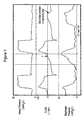
- Figure 1 provides an example.
- the bottom channel is transdiaphragmatic pressure (measured by esophageal and gastric catheters) and reflects true patient inspiratory effort.
- ventilator cycle was triggered several hundred milliseconds after onset of effort (interval between vertical lines) and the inflation cycle continued well beyond the effort.
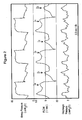
- FIG. 2 A more advanced form of non-synchrony is shown in Figure 2 .
- the inflation cycle of the ventilator extends over two patient cycles. There are, accordingly, two inspiratory efforts within a single inflation phase and there is an additional ineffective effort during the ventilator's expiratory phase.
- the arrows in Figure 2 indicate the location of the extra patient efforts that did not trigger corresponding ventilator cycles.
- Non-synchrony between patient and ventilator is extremely common. Leung et al found that, on average, 28% of patient's efforts are ineffective ( Leung P, Jubran A, Tobin MJ (1997). Comparison of assisted ventilator modes on triggering, patient effort, and dyspnea. Am J Respir Crit Care Med 155:1940-1948 ). Considering that ineffective efforts are the extreme manifestation of non-synchrony, less severe, yet substantial (e.g. first two breaths, Figure 1 ), delays must occur even more frequently. Non-synchrony is believed to cause distress, leading to excessive sedation and sleep disruption, as well as errors in clinical assessment of patients since the respiratory rate of the ventilator can be quite different from that of the patient. Monitoring respiratory rate is a fundamental tool for monitoring critically ill patients on ventilators.
- Trigger delay In current mechanical ventilators, triggering occurs when flow becomes inspiratory (i.e.>0) and exceeds a specified amount, or when airway pressure decreases below the set PEEP (positive end-expiratory pressure) level by a specified amount. Trigger delay has two components. One component is related to ventilator trigger response and sensitivity. Thus, if the response of the ventilator is poor, triggering may not occur immediately when the triggering criteria are reached. Alternatively, the threshold for triggering may be set too high by the user. The component of trigger delay attributable to ventilator response and sensitivity is given by the interval between zero flow crossing (arrow, Figure 1 ) and triggering (second vertical line).
- This component of trigger delay can, however, still be excessive if the user sets an unnecessarily high threshold. This setting may be because of lack of sufficient expertise, or because there was excessive baseline noise at some point, which necessitated a high threshold to avoid auto-triggering. The threshold then remains high even after disappearance of the noise.
- the second component of trigger delay is the time required, beyond the onset of inspiratory effort (T onset ), for expiratory flow to be reduced to zero (interval between first vertical line and the arrow, Figure 1 ).
- This delay is related to the fact that expiratory resistance is usually high in ventilated patients and expiratory time is frequently too short to allow lung volume to return to FRC (functional residual capacity) before the next effort begins.
- elastic recoil pressure is not zero (DH, dynamic hyperinflation).
- Inspiratory effort must first increase enough to offset the elastic recoil pressure associated with DH before flow can become inspiratory, and/or before P aw (airway pressure) decreases below PEEP, in order to trigger the ventilator.
- this component of trigger delay (usually the largest component, seen, for example, Figure 1 ) can be essentially eliminated.
- the ventilator cycle may extend well beyond patient effort, while in those with a low time constant the cycle may end before the end of patient's effort ( Younes M (1993) Patient-ventilator interaction with pressure-assisted modalities of ventilatory support. Seminars in Respiratory Medicine 14:299-322 ; Yamada Y, Du HL (2000) Analysis of the mechanisms of expiratory asynchrony in pressure support ventilation: a mathematical approach. J Appl Physiol 88:2143-2150 ).
- tidal volume in these patients often extends into the volume range where elastance is not constant.
- elastance and resistance may be changing, causing changes in respiratory time constant during the same expiration.
- changes in flow trajectory need not reflect changes in respiratory muscle pressure. This considerably decreases the sensitivity and specificity of flow pattern as a marker of inspiratory effort.
- E passive respiratory system elastance
- K 1 is the laminar component of passive respiratory system resistance
- K 2 is the resistance component related to turbulence (mostly in the endotracheal tube)
- P valve the exhalation/PEEP valve
- R ex resistance of the exhalation tubing
- respiratory muscles were inactive in the first second of expiration (as they usually are). This is represented by P mus of zero (lower panel).
- P mus of zero lower panel
- an inspiratory effort begins.
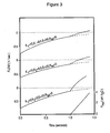
- P mus rises at a rate of 10 cmH 2 O/sec, representative of a normal respiratory drive.
- the three flow waveforms represent, from below upwards, progressively increasing values of K 1 , K 2 , E and R ex .
- the onset of effort results in a sharp change in the flow trajectory that can be readily detected within a very short time after T onset .
- the middle waveform ( Figure 3 ) was generated with values representing the average intensive care patient on mechanical ventilation. Both passive K 1 and passive E are higher than normal, K 2 is that of a #8 endotracheal tube, the most common size used, and the exhalation tubing has a moderate (average) resistance. Note that the change in flow trajectory is considerably less pronounced. An experienced eye, with the benefit of hindsight (i.e. observing the flow waveform for a substantial period after P mus started), may be able to tell that a change in trajectory occurred at 1.0 sec. However, it is not possible to prospectively identify that a trajectory change took place in a timely manner, for the sake of triggering the ventilator.
- the present invention provides a device for detecting the onset of inspiratory effort (T onset ) in a patient on mechanical ventilation, comprising:
- an additional signal is generated to be summed by summing amplifier, said additional signal being generated by multiplying the flow signal by the absolute value of the flow signal and applying a gain factor (K f2 ) to the resulting squared flow signal using an amplifier and wherein K f2 is also used to adjust the trajectory of composite pressure signal baseline in the latter part of the exhalation phase, preferably wherein K f2 is assigned a value corresponding to the K 2 constant of the endotracheal tube in place in the patient.
- K f2 gain factor
- K f is fixed at a default value while adjustment of signal trajectory is made using K v and/or K f2
- K v is fixed at a default value while adjustment of signal trajectory is made using K f and/or K f2 .
- the summing amplifier input related to the volume of gas flow may be omitted.
- the device preferably includes circuitry that precludes T onset identification during a specified period after the end of ventilator's inflation phase.
- the T onset identification circuitry preferably comprises circuitry to obtain the rate of change in amplitude of the composite pressure signal and to obtain the difference between current said rate of change with said rate of change of the composite pressure signal at a specified earlier time, and to generate a T onset signal when said difference exceeds a set threshold value.
- the T onset identification circuitry preferably comprises circuitry to measure the difference between current amplitude of the composite pressure signal and signal amplitude of the composite pressure signal at a specified earlier time, and to generate a T onset signal when said difference exceeds a set threshold value.
- K v and/or K f and/or K f2 are adjusted to produce a horizontal or slightly downward sloping composite pressure signal baseline in the latter part of expiration and the T onset identification circuitry comprises circuitry to measure the difference between current amplitude of the composite pressure signal and amplitude of the composite pressure signal at the most recent point where the composite pressure signal began rising, and to generate a T onset signal when said difference exceeds a set threshold value.
- the generated composite pressure signal is gated to circuitry to identify end of inspiratory effort (T end ) said circuitry comprising:
- circuitry is provided to preclude detection of T end during a specified period following ventilator triggering.
- signals corresponding to T onset are used to trigger ventilator cycles and/or signals corresponding to T end are used to cycle off inflation phase of ventilator.
- Figure 1 contains traces of airway pressure, flow and diaphragm pressure for a patient on mechanical ventilation
- Figure 2 contains further traces of airway pressure, flow and diaphragm pressure for ventilator cycles
- Figure 3 is a graphical representation of the effect of variation in certain parameters on change in trajectory of flow upon start of inspiration
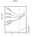
- Figure 4 is a graphical representation of the effect of variation in certain parameters on change in trajectory of composite pressure signal Z upon start of inspiration;
- Figure 5 contains traces of airway pressure, flow and composite pressure signal Z calculated in accordance with the invention
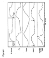
- Figure 6 contains traces of airway pressure, flow, composite pressure signal Z and diaphragm electrical activity, with the signal Z tracing being generated from pressure, flow and volume tracings;
- Figure 7 is a schematic representation of the generation of pressure and flow signals
- Figure 8 is a block diagram of one embodiment of a device operating in accordance with the method of the invention.
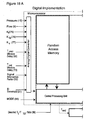
- Figure 9 is a schematic representation of the digital implementation of output functions
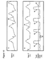
- Figure 10 contains traces of composite pressure signal Z and T onset integrator output
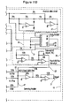
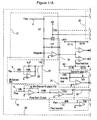
- Figures 11 and 12 show the electrical circuitry used in apparatus of Figure 8 ;
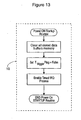
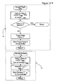
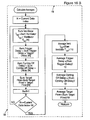
- Figures 13 to 17 contain flow charts for the different functions performed by the output microprocessor shown in Figure 9 ;
- Figure 18 is a block diagram of one embodiment of a fully digital device for carrying out the method of the invention.
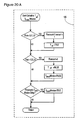
- Figures 19 to 21 contain flow charts for the different functions performed by the fully digital device of Figure 18 .
- the present invention contemplates novel devices for specific and timely identification of respiratory phase transitions within the patient for use in monitoring patient-ventilator interaction or to effect switching of ventilator cycles. These devices represent a progression in complexity that address the problems inherent in the prior art ventilation procedures described above.
- Signal X Flow * K f - P aw
- K f is a constant that converts flow to pressure.
- K f may be an estimated or assumed value of patient's resistance (including endotracheal tube).
- a default value may be used, for example 15 cmH 2 O/l/sec, representing average resistance (including ET tube) in critically ill, mechanically ventilated patients. With such a default value, correction is not perfect, but the signal is more specific (than flow) in reflecting T onset .
- the signal incorporates that component of P mus that was dissipated against R ex (see #3 in Background). For example, if P aw decreases at T onset (because of the lower expiratory flow), this decrease is summed with the component related to flow, resulting in a sharper change in signal trajectory.
- K v is a factor that converts volume to pressure.
- a further improvement is achieved by allowing for non-linearity in the pressure-flow relation.
- the non-linear element is almost exclusively due to endotracheal tube characteristics.
- a suitable alternate approach is to partition the flow component in two parts, one related to the endotracheal tube and the other related to a laminar component of resistance (K f ).
- K f laminar component of resistance
- K f2 may be the commercially available K 2 value of the endotracheal tube in place. This treatment essentially eliminates any artifactual baseline instability related to non-linear pressure-flow behaviour, further reducing the need for extrapolation and enhancing the crispness of the transition.
- E and K 1 are impossible to obtain during assisted ventilation.
- Passive E and R may be available from earlier determinations in which the patient was made passive. These values may be different from the current values, either because the ventilation conditions under which measurements were made were different, or true E and R (i.e. K 1 ) may have changed in the interim.
- Some techniques can be used to estimate E and R during conventional assisted ventilation, but these are not very reliable. An important issue, therefore, is the impact of differences between the K v and real E, and between K f and real resistance, on the baseline of the generated signals and on the sharpness of the transition.
- a further novel aspect of this invention is to completely ignore patient values of E and K 1 and to simply select empiric values of K v and K f that result in a flat or slightly downward sloping baseline in the latter part of expiration. It is clear from Figure 4 that, with respect to baseline pattern (i.e. pattern prior to inspiratory effort), errors can be made to cancel out. Thus, overestimation of E and overestimation of K 1 produce opposite errors. If empiric values of K v and K f , that may have no bearing on actual values, are used, the baseline may be sloping up or down depending on the nature and magnitude of errors.
- a particularly suitable approach for generating signal Z is to use a default K f value of 10 cmH 2 O/l/sec (15 if signal Y is used) and adjust K v to obtain a flat signal baseline.
- a default K v value e.g. 25 cmH 2 O/l, representing average elastance in ICU patients
- K f is adjusted to obtain a flat signal baseline.
- the former approach was found preferable by the inventor as it guarantees a fairly brisk rate of signal rise at T onset .
- Adjustments of K v at a set K f can be implemented by the user employing external inputs for K v and/or K f , with feedback from a graphic display of the generated signal (signal Y or Z).
- selection of the optimum K v and K f values may be done automatically using appropriate software.
- This problem is averted by "blinding" the T onset detection circuitry to the signal during the early part of expiration. This can be done, for example, by gating the signal to the T onset detection circuitry only after a certain delay from onset of expiratory flow (T onset window delay). Alternatively, the T onset detection circuitry may continue to detect T onset during this period but the resulting identification is gated out during this period. Detection of these false triggers can be easily recognized visually by their consistent relation to end of ventilator cycle. The magnitude of the delay (blinding or blanking period) can then be adjusted accordingly. Alternatively, software algorithms can be developed to detect triggering signals with a consistent relation to end of ventilator cycle and automatically adjusting the width of the window.
- K v and K f may have little to do with actual patient elastance and resistance. These values are simply used to facilitate detection of phase transitions. As such the actual value of the signal does not reliably reflect actual Plus, and such signals cannot be used to reliably estimate the work of breathing or quantitative level of pressure output by the patient.
- FIG 6 shows an example of signal Z generated from pressure, flow and volume tracings.
- the signal was generated using a default K f of 10, K f2 of 5.5 (ET tube #8) and a K v of 30.5 selected because it produced a flat baseline in the latter part of expiration. Note the flat baseline of signal Z in the latter part of expiration.
- diaphragmatic electrical activity was also monitored (lowest tracing), and this reflects the activity of the main inspiratory muscle. Note the excellent agreement between the onset of effort identified from the signal Z (arrows) and the onset of diaphragm electrical activity. Note also that T onset (arrows) was identified much earlier than the time at which the ventilator triggered with a conventional triggering algorithm (T trigger , top channel).
- T onset A number of approaches can be used to identify a change in signal trajectory indicative of E ⁇ I transition (T onset ). Some of these include:
- a threshold must be set for the magnitude of change that must be reached for T onset to be declared.
- T end is normally defined as the point at which inspiratory muscle output rapidly declines from its peak value.
- the highest value of signal Y (or Z) during the inflation phase can be identified, in real time, using any of a number of standard techniques. T end is identified when the signal decreases below a specified value or a specified fraction of peak value.
- the signal undergoes a transient artifactual reduction soon after ventilator triggering.
- An extreme example is shown in Figure 5 (arrow indicating Ventilator Trigger Artifact). It is recognized as an artifact, as opposed to natural end of effort (T end ), because the signal resumes rising again. The presence of these artifacts may cause false identification of T end . To avoid this, if false T end identification occurs, the T end identification circuitry is "blinded" to the signal for a set period after T trigger (see T end Window Delay, Figure 5 ) in the same way the T onset identification circuitry is "blinded" to the signal soon after ventilator cycling-off.
- T end Window delay is adjusted accordingly.
- T end occurs soon after ventilator triggering. This is because inspiratory muscle activity can be inhibited if inspiratory flow is high, and the ventilator frequently delivers excessive flow soon after triggering. For this reason, the procedure described above for T end identification may, if used to cycle off the ventilator, result in medically unacceptable inflation times. A back-up procedure is, therefore, required to insure that the duration of inflation phase is physiologically appropriate. The same procedure can be used to insure that the inflation phase does not extend beyond physiologically sound limits. The following is the rationale and method for ensuring that the duration of the inflation phase remains within physiologic limits.
- the duration of the inspiratory phase ranges between 25% and 50% of respiratory cycle duration (T TOT ).
- PAV proportional assist ventilation
- T I /T TOT ratio the ratio of T I to T TOT was also found to be between 0.25 and 0.5. Therefore, one approach to insure that the duration of the inflation phase is within the physiologic range in modes in which end of ventilator cycle is not automatically synchronized with the patient is to constrain the duration of the inflation phase to be between 0.25 and 0.5 of the total cycle duration of patient's own efforts (to be distinguished from duration of ventilator cycles).
- the end of the ventilator cycle is constrained to occur within this physiological range.
- Implementation of this procedure requires knowledge of the true respiratory rate of the patient (as opposed to ventilator rate).
- the true rate of the patient is the sum of ventilator rate, the number of ineffective efforts occurring during the ventilator's exhalation phase (arrows 1 to 3, Figure 2 ) and the number of additional efforts occurring during inflations triggered by an earlier effort (arrows a to c, Figure 2 ).
- the above-described method for identifying T onset detects ineffective efforts occurring during the ventilator's exhalation phase. These can be added to ventilator rate.
- Identification of the extra efforts during the inflation or exhalation phase can be made visually by the user ( Figure 2 ). Alternatively, it can be done automatically using software or analog circuitry. There are several possible approaches to automatically obtain the number of extra efforts that did not result in separate ventilator cycles. One such approach is to differentiate the flow signal and determine the number of positive and negative zero crossings of substantial duration (e.g. >0.4 second, to distinguish from high frequency noise and cardiac artefacts). Another approach is to use Fourier frequency analysis of the flow signal. There are clearly other mathematical approaches to identify the characteristic flow transitions associated with additional efforts. Thus, it is evident that there are many ways by which true respiratory rate of patient can be determined.
- T TOT 60/respiratory rate
- T TOT 60/respiratory rate
- range of inflation times consistent with a physiologic T I /T TOT .
- T TOT 60/respiratory rate
- T TOT the range of inflation times consistent with a physiologic T I /T TOT .
- average T TOT is determined using any of a number of possible methods.
- the desirable duration of the ventilator's inflation phase is then determined by multiplying T TOT by a user selected physiologic T I /T TOT ratio or a suitable default value (e.g. 0.4).
- a timer is reset at the onset of a new T onset or a new ventilator cycle.
- the ventilator ignores other cycling-off commands so long as time elapsed since the last T onset , or onset of ventilator cycle, is less than a set value (e.g. 0.3 of T TOT ).
- the timer may send a cycling-off command once time, since the last T onset , or onset of inflation phase, exceeds a set fraction of average T TOT (e.g. 0.45).
- the fractions used for minimum and/or maximum cycling-off time can be fixed within the ventilator or adjustable by the user.
- An adaptation of this last aspect of the invention is particularly suited for pressure support ventilation (PSV). Because there is often some breath by breath variability in T TOT , setting the end of ventilator cycle to a fixed fraction of average T TOT results in some cycles having higher, and other cycles having lower, T I /T TOT ratios. In this aspect of the invention, only applicable to PSV, rather than causing the ventilator to cycle-off at a predetermined time from the last T onset, the ventilator is cycled off when inspiratory flow reaches a specified amount, with this specified amount selected to provide, on average, the specified T I /T TOT .
- This aspect of the invention is implemented as follows: The interval between successive inspiratory efforts (T TOT ) is determined in several elapsed ventilator cycles.
- the level of inspiratory flow at the specified T I /T TOT fraction is noted. For example, if the specified (desired) fraction is 0.4, and T TOT is 3.0 seconds, flow is measured at 1.2 second after the preceding T onset which triggered a ventilator cycle or, optionally, after the trigger time of the relevant ventilator cycle. The average of several such determinations, in several elapsed breaths, is used as the cycling-off flow threshold in subsequent breaths.
- current cycles destined to have long T TOT automatically have longer inflation cycles. This is so because there is normally a correlation between the duration of inspiratory muscle activity and the T TOT of individual breaths. Thus, in breaths destined to have a long T TOT , inspiratory activity tends to last longer and this, in PSV, delays the point at which a specified cycling-off flow threshold is reached.
- the time of T onset generated by the current invention, can be used to trigger ventilator cycles by providing an appropriate signal to the ventilator's triggering mechanism.
- the end of the ventilator inflation phase can be made to coincide with the end of patient effort, as identified by the present invention, through appropriate connections to the cycling-off mechanism of the ventilation.
- cycling-off can be made to occur at specified times or, in the case of pressure support ventilation, at a specified flow rate, after T onset or after the onset of ventilator cycle. In this application, the user enters a desired T I /T TOT ratio.
- the appropriate time, or flow, to cycle-off is then determined from the inputted T I /T TOT ratio and the value of average patient T TOT , obtained using the present invention. Fourth, cycling off may occur at the identified T end , conditional on this not violating a specified minimum T I /T TOT ratio.
- the information provided by the current invention can be displayed to the user to assist him/her in adjusting ventilator settings to, indirectly, improve patient ventilator interaction.
- the information may be printed out on command or be displayed on a monitor.
- the signal itself can be displayed in real time along with other useful signals such as flow and airway pressure.
- numerical values concerning patient ventilator interaction can be displayed.
- the numerical values may be accompanied by displayed suggestions on how to adjust ventilator settings to reduce the undesirable aspects of current interaction.
- FIG. 7 shows a design and components suitable for obtaining these signals. Although it is possible to obtain these signals by attaching a flow meter and pressure port to the common tube connecting ventilator to patient 1, it is preferable to monitor flow and pressure separately in the inspiratory and expiratory lines and to combine the signals. This is to avoid clogging of the flow meter and to minimize the number of tubing connections extending from near the patient's head to the device.
- a flow meter and pressure port are inserted in the inspiratory line 2 and another set is inserted in the expiratory line 3.
- Each set is connected to appropriate pressure 4 and flow 5 transducers, which generate signals proportional to pressure and flow, respectively.
- the signals from each pressure 4 and flow 5 transducer is conditioned with suitable low pass filters (e.g. 10Hz) and offset and gain circuitry. Suitable calibrations for the pressure and flow signals are 10 cmH 2 O/vol and 1.0 1/sec/volt, respectively.
- the processed inspiratory 6 and expiratory 7 flow signals are summed using a summing amplifier 8 to produce a composite flow signal 9 to be used by the device.
- the inspiratory 10 and expiratory 11 pressure signals are connected to a multiplexer 12.
- a comparator 13 receives the common flow signal 9 and provides a signal 14 to the multiplexer 12 indicating the polarity of the flow signal 9.
- the multiplexer generates a pressure signal 15 composed of the inspiratory pressure signal 10 when flow is expiratory and the expiratory pressure signal 11 when flow is inspiratory. In this fashion the pressure 15 measured at any instant is a close approximation of pressure in the tubing near the patient 1 since at all times a static air column exists between the active transducer and the common ventilator tubing 1 near the patient.
- Pressure and flow signals are routinely generated in modem ventilators using an approach similar to that of Figure 7 . If the device of this invention is incorporated in the ventilator, the pressure and flow signals' generated independently by the ventilator can be used instead.
- FIG. 8 is a block diagram of an analog embodiment of the invention.
- a summing amplifier 16 combines four signals, namely a) the pressure signal 15 suitably inverted 17 and b) the flow signal 9 after suitable amplification 18 using a variable gain amplifier 19. This amplifier 19 provides the desired value of K f (Equations 2, 3 and 4).
- a suitably conditioned and amplified volume signal 20 generated by integrating 21 the flow signal (9) after subtracting a highly filtered (using an ultra low pass filter 22) flow signal 23 to minimize volume drift.
- a variable gain amplifier 24 provides the desired amplification (K v ) of the volume signal (as per Equations 3 and 4).
- a signal 25 comprised of the product [flow*absolute flow] after suitable amplification.
- the signal corresponding to [flow*absolute flow] is generated by processing the flow signal 9 through an absolute value circuit 26, and multiplying the output of this circuit 27 by the flow signal 9 using an analog multiplier circuit 28.
- the resulting signal 29 is then amplified with a variable gain amplifier 30 that provides the desired value of K f2 (Equation 4).
- the signal 31 generated by the summing amplifier 16 is further processed by two circuits, one for detecting the onset of inspiratory effort (T onset identification circuit 32) and one for detecting the end of inspiratory effort (T end identification circuit 33).
- the overall purpose of the first circuit 32 is to measure the increase in the amplitude of the signal 31 during periods in which the signal 31 is rising, within a specific time window in the breath determined by a T onset window circuit 34. This time window begins after a specified delay 35 from the point at which expiratory flow decreases below a specified value (e.g. -0.2 1/sec) during expiration.
- the signal 31 is differentiated using a differentiator 36.
- the differentiated signal 37 is filtered using an appropriate low pass filter (e.g. 5 Hz) 38 to remove high frequency noise.
- the filtered differentiated signal 39 is passed through two comparators. One comparator 40 sends an enabling positive signal 41 when the filtered differentiated signal 39 is positive and the other comparator 42 sends an enabling positive signal 43 when the filtered differentiated signal 39 is negative.
- the unfiltered signal 37 is integrated 44 when two gates 45,46 are enabled.
- the first gate 45 is enabled when the filtered differentiated signal 39 is positive, as detected by the positive comparator 40.
- the second gate 46 is enabled during the specified time window during expiration, as detected by the T onset window circuit 34 and conveyed to the gate by an enabling signal 47.
- the integrator 44 is reset whenever the filtered differentiated signal 39 becomes negative as detected by the negative comparator 42. In this fashion integration begins anew only when the signal is rising within the specified time window.
- the integrator output 48 is received by a comparator 49 which sends out a signal 50, indicating T onset , when integrator output exceeds a specified threshold set by an external EI threshold adjust 51.
- the filtered differentiated signal 39 representing current rate of change in signal
- a comparator compares the current and delayed forms of the filtered differentiated signal.
- a signal, indicating onset of effort is generated when the difference exceeds a threshold value.
- the signal itself 31 may be delayed by a specified amount (e.g. 200 msec).
- a comparator compares the current and delayed forms of the actual signal and generates a signal, indicating onset of effort, when the difference exceeds a threshold value.
- Other approaches are possible within the scope of this invention.
- the signal 31 is first differentiated 52 and the differentiated signal 53 is reintegrated 54.
- the integrator is reset at the onset of inspiratory effort (T onset ) using the signal 50 generated from the T onset identification circuit 32. In this fashion, any baseline offset in the signal 31 is eliminated and the output of the integrator 55 reflects only the increase in signal 31 amplitude from T onset .
- Integrator output 55 is connected to a peak detector circuit 56, which is also reset by the T onset signal 50.
- the output of the peak detector 57 is attenuated 58 with a suitable attenuation factor (e.g. 50%).
- the attenuation factor may be individually adjusted by the user through an external input 59.
- a comparator 60 sends a signal 62 when current integrator output 55 decreases below the attenuated peak detector output 61. In this fashion the end of inspiratory effort is detected when the current integrator output 55 decreases below a set percent of the peak level reached during the current inspiratory effort.
- the signal 31 or 55 transiently decreases at the time of ventilator triggering (Ventilator Trigger Artifact, Figure 5 ). Unless corrected, or allowed for, this artefact may result in false detection of T end .
- a circuit is incorporated to reduce or eliminate the occurrence of false identification of T end .
- the circuit consists of a delay circuit 63 similar to the one used in the T onset identification circuit 34.
- a timer is activated by a T trigger signal 64 received from a T trigger identification circuit 65.
- the latter circuit receives inputs from the pressure 15 and flow 9 signals.
- the pressure signal is differentiated 66 and the resulting signal 67 is directed to a comparator 68 with a suitable reference value (e.g. 15 cmH 2 O/sec).
- the flow signal 9 also is connected to a comparator 69 with a suitable reference value (e.g. 0.3 1/sec).
- the outputs of the two comparators 68,69 are received by an OR gate 70 which sends a T trigger signal 64 to the delay circuit 63 when either the differentiated pressure signal 67 or the flow signal 9 exceed the set value in the respective comparator 68 or 69.
- the delay circuit 63 in turns sends a signal 71 to an AND gate 72 after a specified delay set either externally via a user input 73 or internally as a default value (e.g. 0.2 sec).
- the AND gate 71 also receives the T end signal 62 and sends a final T end signal 74 only if it occurs after the specified delay from T trigger . In this fashion, T end signals generated by the triggering artifacts are screened out.
- the number and types of user inputs may vary depending on how comprehensive the device is and the extent to which user involvement is desired by the manufacturer. In the most comprehensive analog embodiment shown in Figure 8 , there are seven user inputs:
- Some inputs may be deleted by using fixed default values within the device.
- the K f adjust input 75 may be deleted and a fixed value of 10.0 is used.
- a fixed T onset delay value of, for example, 0.3 second may be used, eliminating the T onset window delay input 35.
- a suitable default signal attenuation value (e.g. 50%) may be used replacing the corresponding input 59.
- a T end window delay of 0.2 second may be used eliminating the T end window delay 73.
- signal component related to the non-linear flow function 25 may be eliminated according to Equation 3.
- the K f2 adjust input 76 is deleted.
- the signal component related to volume 20 may be eliminated, according to Equation 2, with corresponding deletion of the K v adjust input 77.
- Certain internal signals need to be displayed to allow the user to adjust the input settings, while others provide the user with the results of monitoring. These signals can be displayed on a monitor 78 included in a freestanding device. Alternatively, if the device is incorporated inside the ventilator, the monitor of the ventilator can be used for this purpose.
- a third embodiment involves directing the device's outputs to an analog to digital converter and displaying the outputs on a separate computer.
- signals representing flow 9, pressure 15 and volume 79 may be displayed on the monitor for general monitoring purposes.
- Signals representing the onset of inspiratory effort 50 (T onset ) and end of inspiratory effort 74 (T end ) are also displayed on the monitor. In the event these signals are to be used to actively control the cycling of the ventilator, they are communicated to the ventilator's cycling mechanism.
- FIG. 9 A block diagram of a preferred embodiment (103) is provided in Figure 9 .
- the flow signal 9 is digitized using an analog to digital converter.
- the central processing unit receives the signals corresponding to T onset 50 and T end 74 of inspiratory effort and signals reflecting ventilator trigger time (T trigger ) 64 and cycling off time (T off, derived from the T onset Window circuit 34 see also 96 in Figure 12 ). The latter two signals may also be obtained directly from the ventilator.
- the user inputs the ventilator mode 88 and the desired T I /T TOT ratio 89.
- the microprocessor calculates trigger delay (T trigger - T onset ) 80 and cycling off delay (T off -T end ) 81.
- the flow signal is differentiated. Additional inspiratory efforts during the inflation phase 82 are identified when the differentiated flow becomes positive after an earlier negative phase (Identify additional efforts function 82, Figure 9 ).
- a "calculate patient rate function" (83, Figure 9 ) calculates respiratory rate of patient 83 from the sum of number of T onset transitions during expiration 50 in the last minute and the number of additional efforts during inflation 82 in the last minute.
- the number of ventilator cycles per minute 84 is calculated from the number of T trigger signals 64 in the last minute.
- the number of ineffective efforts 85 is calculated from the difference between patient respiratory rate 83 and ventilator rate 84.
- the microprocessor also receives a user input indicating the mode of ventilation 88. In the PSV mode, the microprocessor samples flow at the desired T I in several elapsed cycles (Flow at desired T I function 90), and displays the average value on the monitor. The user can take advantage of this information (desired T I or Flow at desired T I ) to adjust ventilator settings to result in optimal T I /T TOT .
- patient respiratory rate (or T TOT ) is inputted to the processor, replacing the "Calculate Patient Rate” function 83. This input is then used to calculate the "Desirable T I " 87 and "Flow at Desired T I " 90.
- Patient respiratory rate may be determined by the user from inspection of chest movements or by observing the flow tracing on the monitor, or automatically using computational methods other than the ones described in the above embodiment 103.
- the pressure 15 and flow 9 signals are permanently connected to the device.
- the first step is to connect the flow meters and pressure ports to the inspiratory 2 and expiratory 3 lines close to the ventilator ( Figure 7 ).
- the device is turned on. Tracing of the Signal 31 appears on the screen ( Figure 10 ). Subsequent steps depend on what inputs are available on the device and user preference. For the most comprehensive analog embodiment ( Figure 8 ) the recommended procedure is as follows:
- Figures 11 and 12 show details of the electrical circuitry used in the preferred embodiment ( Figure 8 ). All circuits are powered by a suitable +/- 8 volts power supply.
- Figure 11 the circuitry used to generate the main signal 31 (block 80 in Figure 8 ) is displayed.
- the summing amplifier 16 with its 4 inputs (17,18,20,25) is shown in the lower right corner of the Figure.
- Circuitry used to process the four inputs prior to the summing amplifier stage is outlined in boxes bearing the same numbers as in the corresponding components of the block diagram ( Figure 8 ).
- the individual electrical components in each circuit are identified by standard electrical symbols and the values of resistors and capacitors indicated are those used in a properly functioning prototype.
- Figure 12 shows details of he electrical circuitry used for T onset identification 32 and T end identification 33.
- the individual electrical components in each circuit are identified by standard electrical symbols and the values of resistors and capacitors indicated are those used in a properly functioning prototype.
- the specific function of each circuit and its connections to other circuits have been described in detail in relation to the block diagram of Figure 8 , and the design of each circuit is standard for the purpose intended in each case. Some of the component circuits need additional explanation, however:
- T onset Window circuit 34 In this circuit the flow signal is connected to a Schmitt trigger circuit (left half of the T onset window circuit 34) characterized by hysteresis. With the indicated values of the different circuit components, the Schmitt circuit sends out a constant voltage (8 volts) whenever flow decreases below -0.21/sec 96. The signal 96 remains on until flow rises to >0.2 I/sec. In this application, the onset of the signal 96 indicates the beginning of the exhalation phase and is also used to mark the end of ventilator cycle (T off ). The output of the Schmitt trigger circuit is connected to a delay circuit with an externally adjustable delay time 35. The output of the delay circuit 97 is received by an AND gate 98.
- the AND gate 98 also receives the output of the Schmitt trigger circuit 96 directly and sends a signal when the T onset window is open, as indicated by the output of the Schmitt trigger circuit 96 but only after the specified delay 35 has elapsed, as indicated by a positive output from the delay circuit 97.
- the output of the AND gate 47 (referred to as Q signal in Figure 12 ) serves multiple functions that include enabling one of the transmission gates 46 in the T onset identification circuit 32.
- T trigger 64 detection circuitry There are many ways by which the time at which the ventilator was triggered can be detected.
- T trigger was detected when the rate of increase in pressure exceeded 15 cmH 2 O/second OR flow increased beyond 0.4 1/second.
- a differentiator 66 was used to obtain ⁇ pressure/ ⁇ t 67.
- a comparator 68 produces a positive signal 99 when ⁇ pressure/ ⁇ t 67 exceeds a set value of 15 cmH 2 O/second.
- a comparator generates a positive signal 100 when flow (9) exceeds 0.41/second.
- Two diodes 101,102 function as an OR gate so that a positive signal (T trigger , 64) is generated when either the ⁇ pressure/ ⁇ t or flow exceed the set respective thresholds.
- T end Window circuit 63 This circuit has four components. First, the Q signal 47, representing time window for T onset detection, is inverted using an inverter 104. The positive phase of this inverted Q signal 105 defines the maximum period during which T end can be located.
- the second component is an AND gate 106 which receives the inverted Q signal 105 and the T trigger signal 64 and sends a positive signal 107 when both its inputs are positive. The positive edge of this signal 107 activates a flip-flop switch 108, which is the third component of the T end Window circuit. The flip-flop switch 108 is reset by the Q signal 47.
- the fourth component is a delay circuit 110 with an adjustable external control 111. The delay circuit 110 receives the output of the flip-flop switch 109. After the set delay, the delay circuit 110 sends out a positive signal 112, which persists until the beginning of the Q signal 47. The output of the delay circuit 112 is one of the two inputs to the main AND gate 72 which generates the Tend signal 74.
- the other components of the T end circuit 33 include the differentiator 52 and integrator 54 that calculate the change in the main signal 31 since the onset of the current effort (55, referred to as S' in Figure 12 ).
- the integrator is reset by the T onset signal 50.
- the peak detector that determines the highest level of signal S' 55 reached during the current effort, is shown 56 and is also reset by the T onset signal 50.
- the output of the peak detector 57 is attenuated with an externally adjustable attenuator 58.
- a comparator 60 receives the output of the attenuated peak signal 61 and the differentiated integrated signal (55, S') and sends a T end signal 62 when the latter 55 decreases below the former 61.
- the T end signal 62 is gated out only if the T end Window is open as indicated by a positive output of the T end Window delay circuit 112. This gating function is performed by an AND gate 72.
- circuitry used in this preferred embodiment is clearly not the only way by which the functions and results contemplated by the current invention can be implemented. Other circuit designs can be used to accomplish the same objectives and these are within the scope of this invention.
- FIGS 13 to 17 show flowcharts for the different functions performed by the output microprocessor ( Figure 9 ).
- the power on start-up routine (113, Figure 13 ) clears the memory and enables the Interrupt Request (IRQ) Process.
- the IRQ process (114, Figure 14 ) is executed at suitable intervals (e.g. every 5msec). It collects data from various inputs (see Figure 9 for inputs), calculates the time derivative of flow and stores collected and derived data in memory. It also checks for the times at which T trigger , T onset , T off, and T end occur and stores these times in memory. Because all these timing inputs are square functions, detection of the times at which these events occurred is based on a simple comparison of current value with the immediately preceding one.
- the main program loop (115, Figure 15 ) performs the various functions identified in the block diagram ( Figure 9 ) in sequence each time a T trigger is detected.
- the flow charts of individual functions are shown in individual diagrams bearing the same numbers.
- the trigger delay function (80, Figure 15 ) when the difference between current T trigger and the last T onset is > 1.0 second, trigger delay is ignored. Thus, the maximum trigger delay allowed is 1.0 second.
- T onset occurs more than 1.0 second before T trigger are usually ventilator cycles triggered by the ventilator and not by the patient.
- the Calculate Ventilator T TOT function (117, Figure 15 ) calculates the interval between current and previous T trigger .
- the cycling off delay function (81, Figure 16 ) calculates the difference between the end of ventilator cycle (T off ) and end of patient effort ((T end ) in current cycle.
- the Identify Additional Efforts function (82, Figure 17 ) the program looks in the interval between T trigger and T off of the previous cycle for points at which ⁇ flow/ ⁇ t crosses from negative to positive and stays positive for 300 msec.
- the program calculates the number of T onset transitions and number of Additional Efforts during inflation in the one-minute interval before the current T trigger .
- PTE refers to efforts occurring during the exhalation phase of the ventilator (i.e. T onset transitions) and PTAE refers to Additional Efforts occurring during the inflation phase of the ventilator.
- the Desirable T I calculate function (87, Figure 16 ) the average patient cycle duration (T TOT ) is calculated from 60/patient respiratory rate calculated in the preceding function (83). Desirable T I is then calculated from average patient T TOT and the desirable T I /T TOT as indicated by the desired T I /T TOT input (89, Figure 9 ).
- the first decision is whether the mode is pressure support ventilation (PSV). If so, the program reads flow at an appropriate time in the immediately preceding ventilator cycle. There are a number of options for the appropriate time at which to measure flow (see next paragraph). Occasionally, the time at which to measure flow may occur after the end of the ventilator cycle, where flow is negative (i.e.
- Ventilator rate (84, Figure 15 ) is calculated from [60/average ventilator T TOT (117)) and the number of Ineffective Efforts (85, Figure 16 ) is calculated from the difference between Average Patient Rate (83, Figure 17 ) and Average Ventilator Rate (84, Figure 15 ).
- the point chosen to measure flow was the preceding Trigger plus an interval corresponding to desirable T I , with the latter based on desired T I /T TOT and average respiratory cycle of patient efforts (87, Figure 16 ).
- T I desired T I /T TOT and average respiratory cycle of patient efforts
- the resulting output of such microprocessor ( Figure 9 ) are displayed on a monitor.
- the information provided can be utilized by the user to adjust ventilator settings in order to optimize patient-ventilator interaction.
- some of the outputs can be channelled to the cycling mechanism of the ventilator to effect such optimization automatically.
- the output of the Target Flow for End of Cycle in the pressure support mode 90 can be used to automatically determine the flow threshold at which the ventilator cycles off in this mode.
- FIG. 18 is a block diagram illustrating one embodiment of a fully digital device.
- the device receives the various inputs either via an A/D converter or directly to the central processing unit (CPU) depending on whether the primary inputs are in digital or analog form.
- these inputs include pressure 15, flow 9, K f 75, K f2 76, K v 77, T onset window delay 35, T end window delay 73, Signal attenuation factor 59, EI threshold 51, Mode 88 and desired T I /T TOT 89.
- the microprocessor executes some functions in real time and others in non real time when a T trigger is identified.
- the non real time functions are similar to those described in detail in relation to the output microprocessor of Figure 9 and the associated flow charts of Figures 13 to 17 . These will not be described further.
- the real time functions are executed at suitable intervals; every 5 to 10 msec being optimal.
- the timed IRQ process 118 is illustrated in flow chart form in Figure 19 . After reading and storing the various inputs, it calculates volume and flow 2 .
- the rate of change in pressure is calculated for use in the Calculate T trigger function 119 and the rate of change in flow is calculated for use in the Identify Additional Efforts function 82.
- the main Signal is then calculated according to Equation 4 and Signal is differentiated for use in the T onset and T end identification functions 121,123.
- T trigger is then looked for using a T trigger calculate function 119 and, if found, the T rigger flag is set to TRUE. This initiates the non real time functions.
- the T onset Window calculate function 120 is used to determine whether this window is open and, if so, the Calculate T onset function 121 is processed to determine whether a T onset occurred.
- the Calculate T end Window function 122 and the Calculate T end function 123 are processed to identify if a T end occurred.
- T trigger calculate function 119 T onset Window calculate function 120, Calculate T onset function 121, Calculate T end Window function 122, and the Calculate T end function 123 are illustrated in flow chart format in Figures 19 to 21 . These charts are self-explanatory particularly in light of the detailed description of the same functions in relation to the block diagram ( Figure 8 ) and circuit diagrams ( Figures 11 and 12 ) of the analog implementation.
- the digital implementation can be simplified to different degrees depending on user and manufacturer preferences.
- the outputs of the device may also be expanded or reduced to meet user needs.
- the present invention provides an apparatus for detecting the onset and the end of inspiratory effort in a patient on mechanical ventilation. Modifications are possible within the scope of the invention, as defined by the appended claims.
Landscapes
- Health & Medical Sciences (AREA)
- Life Sciences & Earth Sciences (AREA)
- General Health & Medical Sciences (AREA)
- Engineering & Computer Science (AREA)
- Anesthesiology (AREA)
- Biomedical Technology (AREA)
- Heart & Thoracic Surgery (AREA)
- Pulmonology (AREA)
- Hematology (AREA)
- Animal Behavior & Ethology (AREA)
- Emergency Medicine (AREA)
- Public Health (AREA)
- Veterinary Medicine (AREA)
- Measurement Of The Respiration, Hearing Ability, Form, And Blood Characteristics Of Living Organisms (AREA)
- Medicines Containing Antibodies Or Antigens For Use As Internal Diagnostic Agents (AREA)
- Measuring Pulse, Heart Rate, Blood Pressure Or Blood Flow (AREA)
- Measuring And Recording Apparatus For Diagnosis (AREA)
Claims (11)
- Vorrichtung zur Feststellung des Einsatzes der Einatmungswirkung (Tonset) eines Patienten bei mechanischer Beatmung, welche Folgendes enthält:eine Schaltung zur Messung des Luftwegdrucks, der Gasflussgeschwindigkeit und des Gasflussvolumens des Patienten,einen Verstärker, um einen Verstärkungsfaktor (Kf) an das Signal zu legen, das die Gasflussgeschwindigkeit repräsentiert, um das Signal in ein Gasflussdrucksignal zu wandeln,einen Verstärker, um einen Verstärkungsfaktor (Kv) an das Signal zu legen, das das Gasflussvolumen repräsentiert, um das Signal in ein Gasvolumendrucksignal zu wandeln,einen Summierverstärker, der ein zusammengesetztes Drucksignal erzeugt, das die Summe von Luftwegdrucksignal, Gasflussdrucksignal und Gasvolumendrucksignal enthält, mit allen Signalen, die eine geeignet eingestellte Polarität aufweisen,Mittel, um Kf und Kv einstellen zu können, um eine gewünschte Trajektorie der zusammengesetzten Drucksignalbasislinie im späteren Teil der Ausatmungsphase anzugeben,eine Schaltung, um das zusammengesetzte Drucksignal während einer geeigneten Periode der Ausatmungsphase auf eine Tonset-Identifikationsschaltung zu führen, wobei die Identifikationsschaltung eine Schaltung enthält, um eine Änderung in der Trajektorie zu erfassen, undMittel zur Erzeugung eines Signals, das Tonset entspricht, wenn eine gemessene Änderung in der Trajektorie des zusammengesetzten Drucksignals eine spezifische Grenze überschreitet.
- Vorrichtung nach Anspruch 1, bei der ein zusätzliches Signal erzeugt wird, das durch den Summierverstärker summiert wird, wobei das zusätzliche Signal durch Multiplikation des Flusssignals mit dem absoluten Wert des Flusssignals gewonnen wird und ein Verstärkungsfaktor Kf2 auf das resultierende quadratische Flusssignal unter Verwendung eines Verstärkers angewendet wird, und wobei Kf2 ferner verwendet wird, um die Trajektorie der zusammengesetzten Drucksignalbasislinie im späteren Teil der Ausatmungsphase einzustellen, wobei vorzugsweise Kf2 einen Wert enthält, der der K2-Konstante des Endotrachealrohrs entspricht, das dem Patienten eingesetzt ist.
- Vorrichtung nach Anspruch 1 oder 2, wobei (a) Kf als Vorschlagswert festgelegt ist, während die Einstellung der Signaltrajektorie unter Verwendung von Kv und/oder Kf2 erfolgt, oder (b) Kv auf einen Vorschlagswert festgelegt ist, während die Einstellung der Signaltrajektorie unter Verwendung Kf und/oder Kf2 erfolgt.
- Vorrichtung nach einem der Ansprüche 1 - 3, bei der der Eingang des Summierverstärkers, der auf den Gasfluss bezogen ist, entfällt.
- Vorrichtung nach einem der Ansprüche 1 - 4, welche eine Schaltung enthält, die eine Tonset-Identifikation während einer speziellen Periode nach Ende der Beatmungsphase des Beamtungsgeräts ausschließt.
- Vorrichtung nach einem der Ansprüche 1 - 5, bei der die Tonset-Identifikationsschaltung eine Schaltung enthält, um eine Änderungsrate in der Amplitude des zusammengesetzten Drucksignals zu erhalten, und um die Differenz zwischen der laufenden Änderungsrate zur Änderungsrate des zusammengesetzten Drucksignals zu einer bestimmten früheren Zeit zu erhalten, und zur Erzeugung eines Tonset-Signals, wenn die Differenz eine bestimmte Grenze überschreitet.
- Vorrichtung nach einem der Ansprüche 1 - 6, bei der die Tonset-Identifikationsschaltung eine Schaltung enthält, um die Differenz zwischen der laufenden Amplitude des zusammengesetzten Drucksignals und der Signalamplitude des zusammengesetzten Drucksignals zu einer spezifischen früheren Zeit zu messen und zur Erzeugung eines Tonset-Signals, wenn die Differenz einen bestimmten Grenzwert überschreitet.
- Vorrichtung nach einem der Ansprüche 1 - 3 und 5 - 7, bei der Kv und/oder Kf und/oder Kf2 eingestellt werden, um eine horizontal oder leicht nach unten fallende zusammengesetzte Drucksignalbasislinie im späteren Teil der Ausatmung zu erzeugen, und die Tonset-Identifikationsschaltung eine Schaltung enthält, um die Differenz zwischen der laufenden Amplitude des zusammengesetzten Drucksignals und der Amplitude des zusammengesetzten Drucksignals des letzten Punktes zu messen, bei dem das zusammengesetzte Drucksignal begonnen hat anzusteigen, und ein Tonset-Signal zu erzeugen, wenn die Differenz eine bestimmte Grenze überschreitet.
- Vorrichtung nach einem der Ansprüche 1 - 8, bei der das erzeugte zusammengesetzte Drucksignal auf eine Schaltung geleitet wird, um das Ende der Einatmungswirkung (Tend) zu identifizieren, wobei die Schaltung Folgendes enthält:eine Schaltung zur Identifizierung der höchsten Amplitude (Spitze) des zusammengesetzten Drucksignals, das während der laufenden Einatmungswirkung erreicht wird,eine Schaltung zur Erfassung, wann die Amplitude des zusammengesetzten Drucksignals unter einen speziellen Wert abfällt nach der Zeit, an der die Spitze erreicht wurde, undeine Schaltung zur Erzeugung eines Signals, das Tend entspricht, wenn die Amplitude des zusammengesetzten Drucksignals unter den bestimmten Wert fällt, vorzugsweise wobei der spezielle Wert ein bestimmter Teil der Spitzenamplitude des zusammengesetzten Drucksignals ist.
- Vorrichtung nach Anspruch 9, bei der eine Schaltung vorgesehen ist, um die Erfassung von Tend während einer speziellen Periode nach der Beatmungstriggerung zu verhindern.
- Vorrichtung nach einem der Ansprüche 1 - 10, bei der Signale, die Tonset entsprechen, verwendet werden, um Beatmungszyklen zu triggern und/oder Signale, die Tend entsprechen, verwendet werden, um die Einatmungsphase des Beatmungsgeräts zu beenden.
Priority Applications (1)
| Application Number | Priority Date | Filing Date | Title |
|---|---|---|---|
| EP09166137A EP2123319A3 (de) | 2002-06-27 | 2003-06-27 | Vorrichtung zur Überwachung und Verbesserung der Wechselwirkung zwischen Patienten und Beatmungsgerät |
Applications Claiming Priority (3)
| Application Number | Priority Date | Filing Date | Title |
|---|---|---|---|
| US39159402P | 2002-06-27 | 2002-06-27 | |
| US391594P | 2002-06-27 | ||
| PCT/CA2003/000976 WO2004002561A2 (en) | 2002-06-27 | 2003-06-27 | Method and device for monitoring and improving patient-ventilator interaction |
Related Child Applications (1)
| Application Number | Title | Priority Date | Filing Date |
|---|---|---|---|
| EP09166137A Division EP2123319A3 (de) | 2002-06-27 | 2003-06-27 | Vorrichtung zur Überwachung und Verbesserung der Wechselwirkung zwischen Patienten und Beatmungsgerät |
Publications (2)
| Publication Number | Publication Date |
|---|---|
| EP1515767A2 EP1515767A2 (de) | 2005-03-23 |
| EP1515767B1 true EP1515767B1 (de) | 2009-08-12 |
Family
ID=30000723
Family Applications (2)
| Application Number | Title | Priority Date | Filing Date |
|---|---|---|---|
| EP03739906A Expired - Lifetime EP1515767B1 (de) | 2002-06-27 | 2003-06-27 | Vorrichtung zur überwachung und verbesserung der wechselwirkung z wischen patienten und beatmungsgerät |
| EP09166137A Withdrawn EP2123319A3 (de) | 2002-06-27 | 2003-06-27 | Vorrichtung zur Überwachung und Verbesserung der Wechselwirkung zwischen Patienten und Beatmungsgerät |
Family Applications After (1)
| Application Number | Title | Priority Date | Filing Date |
|---|---|---|---|
| EP09166137A Withdrawn EP2123319A3 (de) | 2002-06-27 | 2003-06-27 | Vorrichtung zur Überwachung und Verbesserung der Wechselwirkung zwischen Patienten und Beatmungsgerät |
Country Status (7)
| Country | Link |
|---|---|
| US (3) | US20060249148A1 (de) |
| EP (2) | EP1515767B1 (de) |
| AT (1) | ATE439157T1 (de) |
| AU (1) | AU2003280434A1 (de) |
| CA (1) | CA2489108C (de) |
| DE (1) | DE60328786D1 (de) |
| WO (1) | WO2004002561A2 (de) |
Cited By (5)
| Publication number | Priority date | Publication date | Assignee | Title |
|---|---|---|---|---|
| US8783250B2 (en) | 2011-02-27 | 2014-07-22 | Covidien Lp | Methods and systems for transitory ventilation support |
| US9358355B2 (en) | 2013-03-11 | 2016-06-07 | Covidien Lp | Methods and systems for managing a patient move |
| US9375542B2 (en) | 2012-11-08 | 2016-06-28 | Covidien Lp | Systems and methods for monitoring, managing, and/or preventing fatigue during ventilation |
| US9993604B2 (en) | 2012-04-27 | 2018-06-12 | Covidien Lp | Methods and systems for an optimized proportional assist ventilation |
| US11247009B2 (en) | 2015-10-19 | 2022-02-15 | Koninklijke Philips N.V. | Anomaly detection device and method for respiratory mechanics parameter estimation |
Families Citing this family (123)
| Publication number | Priority date | Publication date | Assignee | Title |
|---|---|---|---|---|
| EP1515767B1 (de) * | 2002-06-27 | 2009-08-12 | YRT Limited | Vorrichtung zur überwachung und verbesserung der wechselwirkung z wischen patienten und beatmungsgerät |
| US20050211249A1 (en) * | 2002-11-19 | 2005-09-29 | Mirko Wagner | Ventilator method, ventilator and memory medium |
| WO2004080516A1 (en) | 2003-03-14 | 2004-09-23 | Yrt Limited | Improved synchrony between end of ventilator cycles and end of patient efforts during assisted ventilation |
| US7588033B2 (en) | 2003-06-18 | 2009-09-15 | Breathe Technologies, Inc. | Methods, systems and devices for improving ventilation in a lung area |
| FR2858236B1 (fr) * | 2003-07-29 | 2006-04-28 | Airox | Dispositif et procede de fourniture de gaz respiratoire en pression ou en volume |
| CA2536090C (en) | 2003-08-18 | 2014-07-22 | Anthony D. Wondka | Method and device for non-invasive ventilation with nasal interface |
| EP1778325B1 (de) * | 2004-07-08 | 2010-07-28 | Breas Medical AB | Deltafluss-druckregler |
| CN102512736B (zh) * | 2004-10-20 | 2015-09-02 | 瑞思迈有限公司 | 检测无效吸气努力并改进患者-呼吸机相互作用的系统 |
| CN101454041B (zh) | 2005-09-20 | 2012-12-12 | 呼吸科技公司 | 对患者进行呼吸支持的系统、方法和装置 |
| US7918223B2 (en) * | 2005-11-09 | 2011-04-05 | Carefusion 207, Inc. | System and method for circuit compliance compensated pressure-regulated volume control in a patient respiratory ventilator |
| AU2006343578B2 (en) * | 2006-05-12 | 2012-05-03 | Yrt Limited | Method and device for generating a signal that reflects respiratory efforts in patients on ventilatory support |
| EP2023987B1 (de) | 2006-05-18 | 2016-11-09 | Breathe Technologies, Inc. | Tracheotomie vorrichtung |
| JP2009545384A (ja) | 2006-08-03 | 2009-12-24 | ブリーズ テクノロジーズ, インコーポレイテッド | 最小侵襲性呼吸補助のための方法および装置 |
| US8322339B2 (en) * | 2006-09-01 | 2012-12-04 | Nellcor Puritan Bennett Llc | Method and system of detecting faults in a breathing assistance device |
| US20080066752A1 (en) * | 2006-09-20 | 2008-03-20 | Nellcor Puritan Bennett Inc. | Method and system for circulatory delay compensation in closed-loop control of a medical device |
| DE112007002265T5 (de) * | 2006-09-29 | 2009-10-08 | Draeger Medical Systems, Inc., Andover | System zum Verarbeiten, Herleiten und Anzeigen von Beziehungen zwischen medizinischen Patientenparametern |
| DE102007020038A1 (de) * | 2007-04-27 | 2008-10-30 | Fraunhofer-Gesellschaft zur Förderung der angewandten Forschung e.V. | Nachweis einer Apnoe mit blutdruckabhängig erfassten Signalen |
| WO2008144589A1 (en) | 2007-05-18 | 2008-11-27 | Breathe Technologies, Inc. | Methods and devices for sensing respiration and providing ventilation therapy |
| EP2203206A4 (de) | 2007-09-26 | 2017-12-06 | Breathe Technologies, Inc. | Verfahren und vorrichtungen zur behandlung von schlafapnoe |
| US8567399B2 (en) | 2007-09-26 | 2013-10-29 | Breathe Technologies, Inc. | Methods and devices for providing inspiratory and expiratory flow relief during ventilation therapy |
| DE102007052897B4 (de) * | 2007-11-07 | 2013-02-21 | Dräger Medical GmbH | Verfahren zum automatischen Steuern eines Beatmungssystems sowie zugehöriges Beatmungssystem |
| US8365730B2 (en) * | 2008-03-24 | 2013-02-05 | Covidien Lp | Method and system for classification of photo-plethysmographically detected respiratory effort |
| EP2257328A2 (de) | 2008-03-27 | 2010-12-08 | Nellcor Puritan Bennett LLC | Atemhilfssystem mit lungenrekrutierungsmanövern |
| US8746248B2 (en) | 2008-03-31 | 2014-06-10 | Covidien Lp | Determination of patient circuit disconnect in leak-compensated ventilatory support |
| US8272380B2 (en) | 2008-03-31 | 2012-09-25 | Nellcor Puritan Bennett, Llc | Leak-compensated pressure triggering in medical ventilators |
| EP2313138B1 (de) | 2008-03-31 | 2018-09-12 | Covidien LP | System und verfahren zur bestimmung von lecks in beatmungsgeräten während stabiler phasen innerhalb eines atemzugs |
| US8267085B2 (en) | 2009-03-20 | 2012-09-18 | Nellcor Puritan Bennett Llc | Leak-compensated proportional assist ventilation |
| EP2274036A4 (de) | 2008-04-18 | 2014-08-13 | Breathe Technologies Inc | Verfahren und vorrichtungen zur messung von atmung und zur kontrolle der funktionen eines beatmungsgeräts |
| JP5758799B2 (ja) | 2008-04-18 | 2015-08-05 | ブリーズ・テクノロジーズ・インコーポレーテッド | 呼吸作用を感知し、人工呼吸器の機能を制御するための方法およびデバイス |
| US8457706B2 (en) | 2008-05-16 | 2013-06-04 | Covidien Lp | Estimation of a physiological parameter using a neural network |
| US8484051B2 (en) * | 2008-05-20 | 2013-07-09 | Hartford Fire Insurance Company | System and method for use in connection with an annuity |
| US8485185B2 (en) | 2008-06-06 | 2013-07-16 | Covidien Lp | Systems and methods for ventilation in proportion to patient effort |
| US8726902B2 (en) * | 2008-06-13 | 2014-05-20 | General Electric Company | System and method for smart delivery of backup breaths |
| US20090320836A1 (en) * | 2008-06-30 | 2009-12-31 | Baker Jr Clark R | Method For Regulating Treatment Based On A Medical Device Under Closed-Loop Physiologic Control |
| CA2734296C (en) | 2008-08-22 | 2018-12-18 | Breathe Technologies, Inc. | Methods and devices for providing mechanical ventilation with an open airway interface |
| US8302602B2 (en) | 2008-09-30 | 2012-11-06 | Nellcor Puritan Bennett Llc | Breathing assistance system with multiple pressure sensors |
| US10252020B2 (en) | 2008-10-01 | 2019-04-09 | Breathe Technologies, Inc. | Ventilator with biofeedback monitoring and control for improving patient activity and health |
| FR2937873B1 (fr) * | 2008-11-03 | 2012-08-24 | Assistance Publique Hopitaux Paris | Systeme de quantification du desaccord entre un patient sous assistance respiratoire et un appareil d'assistance correspondant. |
| CN102307521B (zh) * | 2008-12-10 | 2015-02-04 | 皇家飞利浦电子股份有限公司 | 确定弹回率和阻力 |
| US9132250B2 (en) | 2009-09-03 | 2015-09-15 | Breathe Technologies, Inc. | Methods, systems and devices for non-invasive ventilation including a non-sealing ventilation interface with an entrainment port and/or pressure feature |
| WO2010081230A1 (en) * | 2009-01-16 | 2010-07-22 | St. Michael's Hospital | Method and system for measuring changes in inspiratory load |
| JP5779506B2 (ja) | 2009-02-25 | 2015-09-16 | コーニンクレッカ フィリップス エヌ ヴェ | 機械呼吸機能付圧力支持システム |
| JP5802559B2 (ja) * | 2009-02-25 | 2015-10-28 | コーニンクレッカ フィリップス エヌ ヴェ | 患者−換気装置間の同調不良の検出 |
| US8424521B2 (en) | 2009-02-27 | 2013-04-23 | Covidien Lp | Leak-compensated respiratory mechanics estimation in medical ventilators |
| US20100218766A1 (en) * | 2009-02-27 | 2010-09-02 | Nellcor Puritan Bennett Llc | Customizable mandatory/spontaneous closed loop mode selection |
| US8434479B2 (en) | 2009-02-27 | 2013-05-07 | Covidien Lp | Flow rate compensation for transient thermal response of hot-wire anemometers |
| US8418691B2 (en) | 2009-03-20 | 2013-04-16 | Covidien Lp | Leak-compensated pressure regulated volume control ventilation |
| EP2414019B1 (de) | 2009-04-02 | 2017-12-06 | Breathe Technologies, Inc. | Verfahren, systeme und vorrichtungen für nicht-invasive offene beatmung mit gasverabreichungsdüsen im freien raum |
| US9962512B2 (en) | 2009-04-02 | 2018-05-08 | Breathe Technologies, Inc. | Methods, systems and devices for non-invasive ventilation including a non-sealing ventilation interface with a free space nozzle feature |
| EP3351170B1 (de) * | 2009-04-22 | 2023-05-31 | ResMed Pty Ltd | Erkennung von asynchronie |
| US20100288283A1 (en) * | 2009-05-15 | 2010-11-18 | Nellcor Puritan Bennett Llc | Dynamic adjustment of tube compensation factor based on internal changes in breathing tube |
| CN102762250B (zh) | 2009-09-03 | 2017-09-26 | 呼吸科技公司 | 用于包括具有夹带端口和/或压力特征的非密封通气界面的无创通气的方法、系统和装置 |
| US20110126832A1 (en) * | 2009-12-01 | 2011-06-02 | Nellcor Puritan Bennett Llc | Exhalation Valve Assembly |
| US8439037B2 (en) | 2009-12-01 | 2013-05-14 | Covidien Lp | Exhalation valve assembly with integrated filter and flow sensor |
| US8469030B2 (en) | 2009-12-01 | 2013-06-25 | Covidien Lp | Exhalation valve assembly with selectable contagious/non-contagious latch |
| US8469031B2 (en) * | 2009-12-01 | 2013-06-25 | Covidien Lp | Exhalation valve assembly with integrated filter |
| US8439036B2 (en) | 2009-12-01 | 2013-05-14 | Covidien Lp | Exhalation valve assembly with integral flow sensor |
| JP5775882B2 (ja) | 2010-01-22 | 2015-09-09 | コーニンクレッカ フィリップス エヌ ヴェ | 自動的に制御される換気システム |
| USD655405S1 (en) | 2010-04-27 | 2012-03-06 | Nellcor Puritan Bennett Llc | Filter and valve body for an exhalation module |
| USD655809S1 (en) | 2010-04-27 | 2012-03-13 | Nellcor Puritan Bennett Llc | Valve body with integral flow meter for an exhalation module |
| USD653749S1 (en) | 2010-04-27 | 2012-02-07 | Nellcor Puritan Bennett Llc | Exhalation module filter body |
| AU2011292111B2 (en) | 2010-08-16 | 2015-03-26 | Breathe Technologies, Inc. | Methods, systems and devices using LOX to provide ventilatory support |
| WO2012024733A2 (en) * | 2010-08-27 | 2012-03-01 | Resmed Limited | Adaptive cycling for respiratory treatment apparatus |
| US8573207B2 (en) * | 2010-09-28 | 2013-11-05 | Guillermo Gutierrez | Method and system to detect respiratory asynchrony |
| US8939152B2 (en) | 2010-09-30 | 2015-01-27 | Breathe Technologies, Inc. | Methods, systems and devices for humidifying a respiratory tract |
| US20120253216A1 (en) * | 2011-03-30 | 2012-10-04 | Yongji Fu | Respiration analysis using acoustic signal trends |
| US8714154B2 (en) | 2011-03-30 | 2014-05-06 | Covidien Lp | Systems and methods for automatic adjustment of ventilator settings |
| US9629971B2 (en) | 2011-04-29 | 2017-04-25 | Covidien Lp | Methods and systems for exhalation control and trajectory optimization |
| US8776792B2 (en) | 2011-04-29 | 2014-07-15 | Covidien Lp | Methods and systems for volume-targeted minimum pressure-control ventilation |
| EP2779896B1 (de) | 2011-11-16 | 2020-09-23 | St. Michael's Hospital | System zur quantifizierung von timing-unstimmigkeiten zwischen atmungsbemühungen und atmungsunterstützung |
| US9364624B2 (en) | 2011-12-07 | 2016-06-14 | Covidien Lp | Methods and systems for adaptive base flow |
| US9498589B2 (en) | 2011-12-31 | 2016-11-22 | Covidien Lp | Methods and systems for adaptive base flow and leak compensation |
| US9327089B2 (en) | 2012-03-30 | 2016-05-03 | Covidien Lp | Methods and systems for compensation of tubing related loss effects |
| US9144658B2 (en) | 2012-04-30 | 2015-09-29 | Covidien Lp | Minimizing imposed expiratory resistance of mechanical ventilator by optimizing exhalation valve control |
| WO2013173219A1 (en) * | 2012-05-14 | 2013-11-21 | Resmed Motor Technologies Inc. | Control of pressure for breathing comfort |
| US10362967B2 (en) | 2012-07-09 | 2019-07-30 | Covidien Lp | Systems and methods for missed breath detection and indication |
| US9027552B2 (en) | 2012-07-31 | 2015-05-12 | Covidien Lp | Ventilator-initiated prompt or setting regarding detection of asynchrony during ventilation |
| US9295803B2 (en) * | 2012-08-31 | 2016-03-29 | General Electric Company | Ventilator sychronization indicator |
| ES2672520T3 (es) | 2013-03-01 | 2018-06-14 | Breas Medical Ab | Sistema y procedimiento para sincronización de la respiración en un ventilador mecánico |
| USD731049S1 (en) | 2013-03-05 | 2015-06-02 | Covidien Lp | EVQ housing of an exhalation module |
| USD731065S1 (en) | 2013-03-08 | 2015-06-02 | Covidien Lp | EVQ pressure sensor filter of an exhalation module |
| USD736905S1 (en) | 2013-03-08 | 2015-08-18 | Covidien Lp | Exhalation module EVQ housing |
| USD731048S1 (en) | 2013-03-08 | 2015-06-02 | Covidien Lp | EVQ diaphragm of an exhalation module |
| USD744095S1 (en) | 2013-03-08 | 2015-11-24 | Covidien Lp | Exhalation module EVQ internal flow sensor |
| USD693001S1 (en) | 2013-03-08 | 2013-11-05 | Covidien Lp | Neonate expiratory filter assembly of an exhalation module |
| USD701601S1 (en) | 2013-03-08 | 2014-03-25 | Covidien Lp | Condensate vial of an exhalation module |
| USD692556S1 (en) | 2013-03-08 | 2013-10-29 | Covidien Lp | Expiratory filter body of an exhalation module |
| US9950135B2 (en) | 2013-03-15 | 2018-04-24 | Covidien Lp | Maintaining an exhalation valve sensor assembly |
| JP6487425B2 (ja) * | 2013-06-28 | 2019-03-20 | コーニンクレッカ フィリップス エヌ ヴェKoninklijke Philips N.V. | 胸内圧の非侵襲的推定及び/又は胸内圧の非侵襲的推定に基づく呼吸仕事量の計算 |
| US9675771B2 (en) | 2013-10-18 | 2017-06-13 | Covidien Lp | Methods and systems for leak estimation |
| WO2015104669A1 (en) * | 2014-01-09 | 2015-07-16 | Koninklijke Philips N.V. | Patient-ventilator asynchrony detection |
| CN104874056A (zh) * | 2014-02-28 | 2015-09-02 | 北京谊安医疗系统股份有限公司 | 呼吸机触发时间参数监测方法 |
| US9808591B2 (en) | 2014-08-15 | 2017-11-07 | Covidien Lp | Methods and systems for breath delivery synchronization |
| US9950129B2 (en) | 2014-10-27 | 2018-04-24 | Covidien Lp | Ventilation triggering using change-point detection |
| CN107205694B (zh) * | 2015-02-12 | 2021-04-06 | 皇家飞利浦有限公司 | 通过呼吸参数的区域拟合的呼吸参数的同时估计 |
| EP4186548A1 (de) | 2015-04-02 | 2023-05-31 | Hill-Rom Services PTE. LTD. | Maskenleckdetektion für eine atemvorrichtung |
| USD775345S1 (en) | 2015-04-10 | 2016-12-27 | Covidien Lp | Ventilator console |
| EP3302664B1 (de) * | 2015-06-02 | 2020-08-05 | Koninklijke Philips N.V. | Nichtinvasives verfahren zur überwachung des atemstatus eines patienten mittels aufeinanderfolgender parameterschätzung |
| MX2020010523A (es) | 2017-02-27 | 2021-02-09 | Third Pole Inc | Sistemas y metodos para generar oxido nitrico. |
| MX2019009931A (es) | 2017-02-27 | 2020-07-14 | Third Pole Inc | Sistemas y metodos para generacion ambulatoria de oxido nitrico. |
| US10792449B2 (en) | 2017-10-03 | 2020-10-06 | Breathe Technologies, Inc. | Patient interface with integrated jet pump |
| AU2018366291B2 (en) | 2017-11-09 | 2020-09-03 | Autonomous Healthcare, Inc. | Clinical decision support system for patient-ventilator asynchrony detection and management |
| EP3525857B1 (de) | 2017-11-14 | 2020-01-29 | Covidien LP | System für antriebsdruck-spontanatmung |
| US11698064B2 (en) * | 2017-12-29 | 2023-07-11 | Koninklijke Philips N.V. | System and method for operating a pump in a humidifier |
| WO2019222258A1 (en) * | 2018-05-14 | 2019-11-21 | Covidien Lp | Systems and methods for respiratory effort detection utilizing signal distortion |
| CN110755720B (zh) * | 2018-07-27 | 2022-06-14 | 欧姆龙健康医疗事业株式会社 | 呼吸检知方法和系统、气体提供方法和系统以及制氧机 |
| US11517691B2 (en) | 2018-09-07 | 2022-12-06 | Covidien Lp | Methods and systems for high pressure controlled ventilation |
| US11752287B2 (en) | 2018-10-03 | 2023-09-12 | Covidien Lp | Systems and methods for automatic cycling or cycling detection |
| EP3878499A4 (de) * | 2018-11-08 | 2021-11-17 | Shenzhen Mindray Bio-Medical Electronics Co., Ltd. | Verfahren und vorrichtung zur atmungserkennung, beatmungsvorrichtung und speichermedium |
| WO2020232414A1 (en) | 2019-05-15 | 2020-11-19 | Third Pole, Inc. | Architectures for production of nitric oxide |
| WO2020232419A1 (en) | 2019-05-15 | 2020-11-19 | Third Pole, Inc. | Systems and methods for generating nitric oxide |
| EP3969415A4 (de) | 2019-05-15 | 2023-08-16 | Third Pole, Inc. | Elektroden zur erzeugung von stickoxid |
| US11324954B2 (en) | 2019-06-28 | 2022-05-10 | Covidien Lp | Achieving smooth breathing by modified bilateral phrenic nerve pacing |
| EP4069069A4 (de) | 2020-01-11 | 2024-07-03 | Third Pole, Inc. | Systeme und verfahren zur stickoxid-erzeugung mit feuchtigkeitsregelung |
| US11896767B2 (en) | 2020-03-20 | 2024-02-13 | Covidien Lp | Model-driven system integration in medical ventilators |
| EP4167920A4 (de) | 2020-06-18 | 2024-06-12 | Third Pole, Inc. | Systeme und verfahren zur vorbeugung und behandlung von infektionen mit stickoxid |
| WO2022082072A1 (en) | 2020-10-16 | 2022-04-21 | Third Pole, Inc. | Nitric oxide generation process controls |
| AU2022216903A1 (en) * | 2021-02-05 | 2023-08-17 | Fisher & Paykel Healthcare Limited | Determining inspiratory and expiratory parameters in respiratory flow therapy systems |
| WO2023049873A1 (en) | 2021-09-23 | 2023-03-30 | Third Pole, Inc. | Systems and methods for delivering nitric oxide |
| CN114376559B (zh) * | 2022-01-18 | 2023-09-19 | 高昌生医股份有限公司 | 呼吸基准线追踪加速方法 |
| US12569628B2 (en) | 2022-04-14 | 2026-03-10 | Third Pole, Inc. | Delivery of medicinal gas in a liquid medium |
| CN118718186B (zh) * | 2024-06-20 | 2025-09-23 | 深圳市科曼医疗设备有限公司 | 呼吸机通气触发方法及装置、电子设备、存储介质 |
| CN120604983B (zh) * | 2025-07-31 | 2025-10-10 | 中南大学湘雅二医院 | 一种用于吞咽康复中的智能监测系统及方法 |
Family Cites Families (24)
| Publication number | Priority date | Publication date | Assignee | Title |
|---|---|---|---|---|
| US582163A (en) * | 1897-05-11 | Barrel-washer | ||
| US3756229A (en) * | 1970-12-14 | 1973-09-04 | Veriflo Corp | Ventilator |
| US4323064A (en) * | 1976-10-26 | 1982-04-06 | Puritan-Bennett Corporation | Volume ventilator |
| FR2483785A1 (fr) * | 1980-06-10 | 1981-12-11 | Air Liquide | Respirateur a correction automatique de ventilation |
| US4368740A (en) * | 1980-11-03 | 1983-01-18 | Binder Andy S | Physiologic analyzer |
| GB8704104D0 (en) * | 1987-02-21 | 1987-03-25 | Manitoba University Of | Respiratory system load apparatus |
| US5632269A (en) * | 1989-09-22 | 1997-05-27 | Respironics Inc. | Breathing gas delivery method and apparatus |
| US5038771A (en) * | 1990-01-25 | 1991-08-13 | Dietz Henry G | Method and apparatus for respiratory therapy using intermittent flow having automatic adjustment of a dose of therapeutic gas to the rate of breathing |
| US5161525A (en) | 1990-05-11 | 1992-11-10 | Puritan-Bennett Corporation | System and method for flow triggering of pressure supported ventilation |
| US5271389A (en) * | 1992-02-12 | 1993-12-21 | Puritan-Bennett Corporation | Ventilator control system that generates, measures, compares, and corrects flow rates |
| BR9304638A (pt) | 1993-12-06 | 1995-07-25 | Intermed Equipamento Medico Ho | Sistema de controle de ciclo respiratório |
| US6105575A (en) * | 1994-06-03 | 2000-08-22 | Respironics, Inc. | Method and apparatus for providing positive airway pressure to a patient |
| US5598838A (en) * | 1995-04-07 | 1997-02-04 | Healthdyne Technologies, Inc. | Pressure support ventilatory assist system |
| US6000396A (en) * | 1995-08-17 | 1999-12-14 | University Of Florida | Hybrid microprocessor controlled ventilator unit |
| US5881717A (en) * | 1997-03-14 | 1999-03-16 | Nellcor Puritan Bennett Incorporated | System and method for adjustable disconnection sensitivity for disconnection and occlusion detection in a patient ventilator |
| CA2239673A1 (en) * | 1998-06-04 | 1999-12-04 | Christer Sinderby | Automatic adjustment of applied levels of ventilatory support and extrinsic peep by closed-loop control of neuro-ventilatory efficiency |
| US6220244B1 (en) * | 1998-09-15 | 2001-04-24 | Mclaughlin Patrick L. | Conserving device for use in oxygen delivery and therapy |
| EP2263730A3 (de) * | 1999-01-15 | 2017-03-15 | Resmed Limited | Verfahren und Vorrichtung zum Ausgleich des intrinischen positiven endexpiratorischen Druckes |
| CA2362164A1 (en) | 1999-02-03 | 2000-08-10 | Paul Bradford Blanch | Method and apparatus for nullifying the imposed work of breathing |
| US6439229B1 (en) * | 2000-08-08 | 2002-08-27 | Newport Medical Instruments, Inc. | Pressure support ventilation control system and method |
| JP4293581B2 (ja) * | 2000-09-21 | 2009-07-08 | 日本特殊陶業株式会社 | 酸素濃縮器及び制御装置並びに記録媒体 |
| US6626175B2 (en) * | 2000-10-06 | 2003-09-30 | Respironics, Inc. | Medical ventilator triggering and cycling method and mechanism |
| US6622726B1 (en) * | 2000-10-17 | 2003-09-23 | Newport Medical Instruments, Inc. | Breathing apparatus and method |
| EP1515767B1 (de) * | 2002-06-27 | 2009-08-12 | YRT Limited | Vorrichtung zur überwachung und verbesserung der wechselwirkung z wischen patienten und beatmungsgerät |
-
2003
- 2003-06-27 EP EP03739906A patent/EP1515767B1/de not_active Expired - Lifetime
- 2003-06-27 WO PCT/CA2003/000976 patent/WO2004002561A2/en not_active Ceased
- 2003-06-27 US US10/517,384 patent/US20060249148A1/en not_active Abandoned
- 2003-06-27 DE DE60328786T patent/DE60328786D1/de not_active Expired - Lifetime
- 2003-06-27 EP EP09166137A patent/EP2123319A3/de not_active Withdrawn
- 2003-06-27 AT AT03739906T patent/ATE439157T1/de not_active IP Right Cessation
- 2003-06-27 AU AU2003280434A patent/AU2003280434A1/en not_active Abandoned
- 2003-06-27 CA CA2489108A patent/CA2489108C/en not_active Expired - Lifetime
- 2003-06-27 US US10/606,751 patent/US7484508B2/en not_active Expired - Fee Related
-
2008
- 2008-12-31 US US12/318,555 patent/US20090107502A1/en not_active Abandoned
Cited By (5)
| Publication number | Priority date | Publication date | Assignee | Title |
|---|---|---|---|---|
| US8783250B2 (en) | 2011-02-27 | 2014-07-22 | Covidien Lp | Methods and systems for transitory ventilation support |
| US9993604B2 (en) | 2012-04-27 | 2018-06-12 | Covidien Lp | Methods and systems for an optimized proportional assist ventilation |
| US9375542B2 (en) | 2012-11-08 | 2016-06-28 | Covidien Lp | Systems and methods for monitoring, managing, and/or preventing fatigue during ventilation |
| US9358355B2 (en) | 2013-03-11 | 2016-06-07 | Covidien Lp | Methods and systems for managing a patient move |
| US11247009B2 (en) | 2015-10-19 | 2022-02-15 | Koninklijke Philips N.V. | Anomaly detection device and method for respiratory mechanics parameter estimation |
Also Published As
| Publication number | Publication date |
|---|---|
| US7484508B2 (en) | 2009-02-03 |
| EP2123319A3 (de) | 2010-03-10 |
| US20090107502A1 (en) | 2009-04-30 |
| WO2004002561A2 (en) | 2004-01-08 |
| EP2123319A2 (de) | 2009-11-25 |
| EP1515767A2 (de) | 2005-03-23 |
| US20040050387A1 (en) | 2004-03-18 |
| ATE439157T1 (de) | 2009-08-15 |
| WO2004002561A3 (en) | 2004-04-08 |
| DE60328786D1 (de) | 2009-09-24 |
| CA2489108C (en) | 2014-02-11 |
| CA2489108A1 (en) | 2004-01-08 |
| US20060249148A1 (en) | 2006-11-09 |
| AU2003280434A1 (en) | 2004-01-19 |
Similar Documents
| Publication | Publication Date | Title |
|---|---|---|
| US7484508B2 (en) | Method and device for monitoring and improving patient-ventilator interaction | |
| US8920333B2 (en) | Method and device for generating of a signal that reflects respiratory efforts in patients on ventilatory support | |
| US7819815B2 (en) | Synchrony between end of ventilator cycles and end of patient efforts during assisted ventilation | |
| JP4613213B2 (ja) | 被験者の呼吸器官の生体力学的動作を監視し、生体力学的動作に基づいて人工呼吸器を制御する装置 | |
| CN102512736B (zh) | 检测无效吸气努力并改进患者-呼吸机相互作用的系统 | |
| US5884622A (en) | Automatic determination of passive elastic and resistive properties of the respiratory system during assisted mechanical ventilation | |
| JP5016615B2 (ja) | 閉塞睡眠時無呼吸の改良された流量制限検出の方法及び装置 | |
| EP1005830B1 (de) | An die Bedürfnisse des Patienten angepasste künstliche Beatmung | |
| US9526855B2 (en) | Administration of CPAP treatment pressure in presence of apnea | |
| JP3320422B2 (ja) | 患者の呼吸気系の少なくとも2つのパラメータを決定する装置 | |
| JP2003531694A (ja) | 換気支援中の呼吸器系の抵抗を求める方法および装置 | |
| EP3302664B1 (de) | Nichtinvasives verfahren zur überwachung des atemstatus eines patienten mittels aufeinanderfolgender parameterschätzung | |
| AU2020321288B2 (en) | Device for supportive ventilation of a living being and computer program | |
| CA2519041C (en) | Improved synchrony between end of ventilator cycles and end of patient efforts during assisted ventilation | |
| US12447296B1 (en) | Systems and methods of determining therapeutic expiratory pressure automatically | |
| JP3558167B6 (ja) | 患者の呼吸の必要性と調和する補助された換気方法及び装置 | |
| Dellaca | Expiratory flow limitation (EFL): overview |
Legal Events
| Date | Code | Title | Description |
|---|---|---|---|
| PUAI | Public reference made under article 153(3) epc to a published international application that has entered the european phase |
Free format text: ORIGINAL CODE: 0009012 |
|
| AK | Designated contracting states |
Kind code of ref document: A2 Designated state(s): AT BE BG CH CY CZ DE DK EE ES FI FR GB GR HU IE IT LI LU MC NL PT RO SE SI SK TR |
|
| AX | Request for extension of the european patent |
Extension state: AL LT LV MK |
|
| 17P | Request for examination filed |
Effective date: 20041223 |
|
| 17Q | First examination report despatched |
Effective date: 20061220 |
|
| RTI1 | Title (correction) |
Free format text: DEVICE FOR MONITORING AND IMPROVING PATIENT-VENTILATOR INTERACTION |
|
| GRAP | Despatch of communication of intention to grant a patent |
Free format text: ORIGINAL CODE: EPIDOSNIGR1 |
|
| GRAS | Grant fee paid |
Free format text: ORIGINAL CODE: EPIDOSNIGR3 |
|
| GRAA | (expected) grant |
Free format text: ORIGINAL CODE: 0009210 |
|
| AK | Designated contracting states |
Kind code of ref document: B1 Designated state(s): AT BE BG CH CY CZ DE DK EE ES FI FR GB GR HU IE IT LI LU MC NL PT RO SE SI SK TR |
|
| AX | Request for extension of the european patent |
Extension state: AL LT LV MK |
|
| REG | Reference to a national code |
Ref country code: GB Ref legal event code: FG4D |
|
| REG | Reference to a national code |
Ref country code: CH Ref legal event code: EP |
|
| REG | Reference to a national code |
Ref country code: IE Ref legal event code: FG4D |
|
| REF | Corresponds to: |
Ref document number: 60328786 Country of ref document: DE Date of ref document: 20090924 Kind code of ref document: P |
|
| LTIE | Lt: invalidation of european patent or patent extension |
Effective date: 20090812 |
|
| PG25 | Lapsed in a contracting state [announced via postgrant information from national office to epo] |
Ref country code: SE Free format text: LAPSE BECAUSE OF FAILURE TO SUBMIT A TRANSLATION OF THE DESCRIPTION OR TO PAY THE FEE WITHIN THE PRESCRIBED TIME-LIMIT Effective date: 20090812 Ref country code: FI Free format text: LAPSE BECAUSE OF FAILURE TO SUBMIT A TRANSLATION OF THE DESCRIPTION OR TO PAY THE FEE WITHIN THE PRESCRIBED TIME-LIMIT Effective date: 20090812 Ref country code: ES Free format text: LAPSE BECAUSE OF FAILURE TO SUBMIT A TRANSLATION OF THE DESCRIPTION OR TO PAY THE FEE WITHIN THE PRESCRIBED TIME-LIMIT Effective date: 20091123 Ref country code: AT Free format text: LAPSE BECAUSE OF FAILURE TO SUBMIT A TRANSLATION OF THE DESCRIPTION OR TO PAY THE FEE WITHIN THE PRESCRIBED TIME-LIMIT Effective date: 20090812 |
|
| NLV1 | Nl: lapsed or annulled due to failure to fulfill the requirements of art. 29p and 29m of the patents act | ||
| PG25 | Lapsed in a contracting state [announced via postgrant information from national office to epo] |
Ref country code: SI Free format text: LAPSE BECAUSE OF FAILURE TO SUBMIT A TRANSLATION OF THE DESCRIPTION OR TO PAY THE FEE WITHIN THE PRESCRIBED TIME-LIMIT Effective date: 20090812 Ref country code: NL Free format text: LAPSE BECAUSE OF FAILURE TO SUBMIT A TRANSLATION OF THE DESCRIPTION OR TO PAY THE FEE WITHIN THE PRESCRIBED TIME-LIMIT Effective date: 20090812 |
|
| PG25 | Lapsed in a contracting state [announced via postgrant information from national office to epo] |
Ref country code: PT Free format text: LAPSE BECAUSE OF FAILURE TO SUBMIT A TRANSLATION OF THE DESCRIPTION OR TO PAY THE FEE WITHIN THE PRESCRIBED TIME-LIMIT Effective date: 20091212 Ref country code: BG Free format text: LAPSE BECAUSE OF FAILURE TO SUBMIT A TRANSLATION OF THE DESCRIPTION OR TO PAY THE FEE WITHIN THE PRESCRIBED TIME-LIMIT Effective date: 20091112 |
|
| PG25 | Lapsed in a contracting state [announced via postgrant information from national office to epo] |
Ref country code: EE Free format text: LAPSE BECAUSE OF FAILURE TO SUBMIT A TRANSLATION OF THE DESCRIPTION OR TO PAY THE FEE WITHIN THE PRESCRIBED TIME-LIMIT Effective date: 20090812 Ref country code: DK Free format text: LAPSE BECAUSE OF FAILURE TO SUBMIT A TRANSLATION OF THE DESCRIPTION OR TO PAY THE FEE WITHIN THE PRESCRIBED TIME-LIMIT Effective date: 20090812 Ref country code: CZ Free format text: LAPSE BECAUSE OF FAILURE TO SUBMIT A TRANSLATION OF THE DESCRIPTION OR TO PAY THE FEE WITHIN THE PRESCRIBED TIME-LIMIT Effective date: 20090812 Ref country code: RO Free format text: LAPSE BECAUSE OF FAILURE TO SUBMIT A TRANSLATION OF THE DESCRIPTION OR TO PAY THE FEE WITHIN THE PRESCRIBED TIME-LIMIT Effective date: 20090812 |
|
| PG25 | Lapsed in a contracting state [announced via postgrant information from national office to epo] |
Ref country code: SK Free format text: LAPSE BECAUSE OF FAILURE TO SUBMIT A TRANSLATION OF THE DESCRIPTION OR TO PAY THE FEE WITHIN THE PRESCRIBED TIME-LIMIT Effective date: 20090812 |
|
| PLBE | No opposition filed within time limit |
Free format text: ORIGINAL CODE: 0009261 |
|
| STAA | Information on the status of an ep patent application or granted ep patent |
Free format text: STATUS: NO OPPOSITION FILED WITHIN TIME LIMIT |
|
| PG25 | Lapsed in a contracting state [announced via postgrant information from national office to epo] |
Ref country code: BE Free format text: LAPSE BECAUSE OF FAILURE TO SUBMIT A TRANSLATION OF THE DESCRIPTION OR TO PAY THE FEE WITHIN THE PRESCRIBED TIME-LIMIT Effective date: 20090812 |
|
| 26N | No opposition filed |
Effective date: 20100517 |
|
| PG25 | Lapsed in a contracting state [announced via postgrant information from national office to epo] |
Ref country code: GR Free format text: LAPSE BECAUSE OF FAILURE TO SUBMIT A TRANSLATION OF THE DESCRIPTION OR TO PAY THE FEE WITHIN THE PRESCRIBED TIME-LIMIT Effective date: 20091113 |
|
| PG25 | Lapsed in a contracting state [announced via postgrant information from national office to epo] |
Ref country code: MC Free format text: LAPSE BECAUSE OF NON-PAYMENT OF DUE FEES Effective date: 20100630 |
|
| REG | Reference to a national code |
Ref country code: CH Ref legal event code: PL |
|
| PG25 | Lapsed in a contracting state [announced via postgrant information from national office to epo] |
Ref country code: IT Free format text: LAPSE BECAUSE OF FAILURE TO SUBMIT A TRANSLATION OF THE DESCRIPTION OR TO PAY THE FEE WITHIN THE PRESCRIBED TIME-LIMIT Effective date: 20090812 |
|
| PG25 | Lapsed in a contracting state [announced via postgrant information from national office to epo] |
Ref country code: LI Free format text: LAPSE BECAUSE OF NON-PAYMENT OF DUE FEES Effective date: 20100630 Ref country code: CH Free format text: LAPSE BECAUSE OF NON-PAYMENT OF DUE FEES Effective date: 20100630 Ref country code: IE Free format text: LAPSE BECAUSE OF NON-PAYMENT OF DUE FEES Effective date: 20100627 |
|
| PG25 | Lapsed in a contracting state [announced via postgrant information from national office to epo] |
Ref country code: CY Free format text: LAPSE BECAUSE OF FAILURE TO SUBMIT A TRANSLATION OF THE DESCRIPTION OR TO PAY THE FEE WITHIN THE PRESCRIBED TIME-LIMIT Effective date: 20090812 |
|
| PG25 | Lapsed in a contracting state [announced via postgrant information from national office to epo] |
Ref country code: LU Free format text: LAPSE BECAUSE OF NON-PAYMENT OF DUE FEES Effective date: 20100627 Ref country code: HU Free format text: LAPSE BECAUSE OF FAILURE TO SUBMIT A TRANSLATION OF THE DESCRIPTION OR TO PAY THE FEE WITHIN THE PRESCRIBED TIME-LIMIT Effective date: 20100213 |
|
| PG25 | Lapsed in a contracting state [announced via postgrant information from national office to epo] |
Ref country code: TR Free format text: LAPSE BECAUSE OF FAILURE TO SUBMIT A TRANSLATION OF THE DESCRIPTION OR TO PAY THE FEE WITHIN THE PRESCRIBED TIME-LIMIT Effective date: 20090812 |
|
| REG | Reference to a national code |
Ref country code: FR Ref legal event code: PLFP Year of fee payment: 14 |
|
| REG | Reference to a national code |
Ref country code: FR Ref legal event code: PLFP Year of fee payment: 15 |
|
| REG | Reference to a national code |
Ref country code: FR Ref legal event code: PLFP Year of fee payment: 16 |
|
| REG | Reference to a national code |
Ref country code: DE Ref legal event code: R082 Ref document number: 60328786 Country of ref document: DE Representative=s name: MUELLER SCHUPFNER & PARTNER PATENT- UND RECHTS, DE |
|
| PGFP | Annual fee paid to national office [announced via postgrant information from national office to epo] |
Ref country code: FR Payment date: 20200513 Year of fee payment: 18 Ref country code: DE Payment date: 20200515 Year of fee payment: 18 |
|
| PGFP | Annual fee paid to national office [announced via postgrant information from national office to epo] |
Ref country code: GB Payment date: 20200526 Year of fee payment: 18 |
|
| REG | Reference to a national code |
Ref country code: DE Ref legal event code: R119 Ref document number: 60328786 Country of ref document: DE |
|
| GBPC | Gb: european patent ceased through non-payment of renewal fee |
Effective date: 20210627 |
|
| PG25 | Lapsed in a contracting state [announced via postgrant information from national office to epo] |
Ref country code: GB Free format text: LAPSE BECAUSE OF NON-PAYMENT OF DUE FEES Effective date: 20210627 Ref country code: DE Free format text: LAPSE BECAUSE OF NON-PAYMENT OF DUE FEES Effective date: 20220101 |
|
| PG25 | Lapsed in a contracting state [announced via postgrant information from national office to epo] |
Ref country code: FR Free format text: LAPSE BECAUSE OF NON-PAYMENT OF DUE FEES Effective date: 20210630 |