EP1515579A2 - Selbsttätiges Meterablesesystem unter Verwendung von rückwärtszählender Zeitgebervorrichtung - Google Patents
Selbsttätiges Meterablesesystem unter Verwendung von rückwärtszählender Zeitgebervorrichtung Download PDFInfo
- Publication number
- EP1515579A2 EP1515579A2 EP04255316A EP04255316A EP1515579A2 EP 1515579 A2 EP1515579 A2 EP 1515579A2 EP 04255316 A EP04255316 A EP 04255316A EP 04255316 A EP04255316 A EP 04255316A EP 1515579 A2 EP1515579 A2 EP 1515579A2
- Authority
- EP
- European Patent Office
- Prior art keywords
- clock
- countdown signal
- endpoint
- clock countdown
- signal
- Prior art date
- Legal status (The legal status is an assumption and is not a legal conclusion. Google has not performed a legal analysis and makes no representation as to the accuracy of the status listed.)
- Withdrawn
Links
Images


Classifications
-
- H—ELECTRICITY
- H04—ELECTRIC COMMUNICATION TECHNIQUE
- H04Q—SELECTING
- H04Q9/00—Arrangements in telecontrol or telemetry systems for selectively calling a substation from a main station, in which substation desired apparatus is selected for applying a control signal thereto or for obtaining measured values therefrom
-
- H—ELECTRICITY
- H04—ELECTRIC COMMUNICATION TECHNIQUE
- H04Q—SELECTING
- H04Q2209/00—Arrangements in telecontrol or telemetry systems
- H04Q2209/40—Arrangements in telecontrol or telemetry systems using a wireless architecture
-
- H—ELECTRICITY
- H04—ELECTRIC COMMUNICATION TECHNIQUE
- H04Q—SELECTING
- H04Q2209/00—Arrangements in telecontrol or telemetry systems
- H04Q2209/60—Arrangements in telecontrol or telemetry systems for transmitting utility meters data, i.e. transmission of data from the reader of the utility meter
Definitions
- the present invention relates to a method and system for collecting data from remote utility meters. More particularly, the present invention describes a method and a system for establishing communication between a reader of an automated meter reading system and a plurality of utility meters within that system utilizing the bit sequence of a sequence inversion keyed countdown timer.
- Wireless automatic meter reading systems are well known.
- each utility meter is provided with some type of encoder/receiver/transmitter endpoint, such as the Itron, Inc. ERT.
- that endpoint is likely battery-powered.
- the endpoint collects the meter readings and periodically transmits those readings over a network to a central station.
- the power limitations imposed by the need for the endpoint to be battery powered and by regulations governing radio transmissions often prevent direct radio transmissions to the central station.
- wireless meter reading systems utilize a layered network of overlapping intermediate receiving stations that receive transmissions from a group of meter encoders and forward those messages on to the next higher layer in the network as described, for example, in U.S. Patent No.
- the FCC modified Part 15 of the Radio Spectrum Regulation, which governs unlicensed devices.
- the modification authorized wireless network products to operate in the industrial, scientific, and medical (ISM) bands using spread spectrum modulation.
- ISM industrial, scientific, and medical
- the ISM frequencies that may be used include 902 to 928 MHz, 2.4 to 2.4835 GHz, and 5.725 to 5.850 GHz.
- the FCC allows users to operate spread spectrum wireless products, such as utility metering systems, without obtaining FCC licenses if the products meet certain requirements. This deregulation of the frequency spectrum eliminates the need for the user organizations to perform costly and time-consuming frequency planning to coordinate radio installations that will avoid interference with existing radio systems.
- synchronization between a transmitter and a receiver is accomplished by using a synchronization pulse, which may interfere with hardware clock recovery, or by using Barker coding type approaches, which require receivers to stay on at length.
- these current synchronization techniques do not prevent collisions in endbound data packets as the endpoints are not time synchronized between the transmitter and receiver. This lack of endpoint synchronization further results in limitations on individual cell capacities as well as inherent difficulties in implementing message integration techniques.
- a method for endpoint synchronization of a high capacity data stream using sequence inversion keying Utilizing sequence inversion keying, a metering network is assigned a system ID that is represented by a specific bit number sequence. Through careful selection of the bit sequence, multiple system ID's, each with their own specific bit sequence, can be implemented within the same geographic area.
- SIK sequence inversion keying
- Each utility meter includes a receiver that includes means for receiving a signal transmitted by the reader of either a fixed or mobile utility station.
- the signal includes a series of unique data sequences which are specifically selected to identify a particular network from which information is desired to be collected. Using these unique data sequences, a utility meter can quickly determine whether the reader is requesting information from the utility meter. If the signal fails to include its unique data sequence, the utility meter immediately shuts down eliminating further battery consumption.
- the utility meter continues listening to the signal through which are transmitted additional sequences that can correspond to specific actions to be undertaken by utility meters or to notices indicating when command and control data is to be transmitted. In the event that further command and control data is to be sent, the utility meter shuts down until the time indicated in the prior transmission at which time it powers up and listens to the sequence pertaining to command and control data In this way, battery consumption is reduced by eliminating the wait time of the utility meter with respect to the transmission of command and control data. Accordingly, the method of the present invention provides for two layers of battery savings wherein one layer comprises quickly identifying desired networks using a unique data sequence and a second layer comprises synchronization with regard to receipt of command and control data.
- Various embodiments of the present invention are directed to addressing various needs in connection with ensuring full coverage and receiving load-shedding feedback using an automatic wireless meter reading system.
- an automatic meter reading system that includes a head end controller and an endpoint that is interfaced to a utility meter.
- the head end controller and the endpoint communicate via RF communication.
- the endpoint includes an internal clock that synchronizes itself to a clock countdown signal.
- the clock countdown signal is generated by the head end controller through use of sequence inversion keying.
- the clock countdown signal is preferably generated for less than 60 seconds for each hour in the day, and more preferably for 30 seconds or less for each hour in the day.
- the internal clock of the endpoint is preferably synchronized to the countdown signal every hour of every day.
- the internal clock may be synchronized to the clock countdown signal at any point during the generation of the clock countdown signal.
- the endpoint is battery powered.
- the endpoint preferably operates on that battery power for less than 200 milliseconds, and more preferably 100 or less milliseconds, to synchronize the internal clock of the endpoint to the clock countdown signal.
- the endpoint includes the ability to re-acquire the clock countdown signal from the head end controller should the endpoint lose the communication with the controller.
- a method for communication in an automatic meter reading system includes the steps of:
- the present invention is generally directed to a method and a system for collecting data from a plurality of automatic meter reading networks, each comprising multiple utility meters with interfacing endpoints, within a designated area.
- network ID's represented by specific data bit sequences
- data from specific individual networks in the geographic area can be collected. While the present invention is not necessarily limited to such an application, the invention will be better appreciated using a discussion of example embodiments in such a specific context.
- geographic area 100 shown as a residential neighborhood, including a plurality of houses 102a, 102b, 102c, 102d, 102e, 102f, 102g and 102h.
- geographic area 100 is depicted as including two unique automatic meter reading networks within the boundaries of the geographic area 100.
- a first automatic meter reading network 104 comprises a plurality of remote first endpoints 106, for monitoring electrical consumption within the individual houses 102a, 102b, 102c, 102d, 102e, 102f, 102g and 102h.
- a second automatic meter reading network 108 comprises a plurality of remote second endpoints 110 for monitoring water consumption within the individual houses 102a, 102b, 102c, 102d, 102e, 102f, 102g and 102h.
- An alternative or additional network could include a plurality of endpoints interface to gas meters.
- geographic area 100 can include multi-occupant dwellings, such as apartment buildings, condos, townhomes or duplexes, each multi-occupant dwelling having multiple remote electrical utility meters 106 and/or multiple remote water utility meters 110.
- geographic area 100 can comprise alternative municipal uses including commercial and manufacturing facilities alone or in combination with residential facilities.
- remote first endpoint 106 comprises an electrical power source, an electrical consumption meter, a receiver, a transmitter and a logic circuit.
- remote first endpoint 106 could be battery powered.
- the endpoints 106 are preferably Itron, Inc. ERT modules.
- remote second endpoint 110 comprises a battery power source, a water consumption meter, a receiver, a transmitter and a logic circuit.
- remote second endpoint 110 could be electrically powered through hardwiring to an electrical power source.
- the endpoints 106 are preferably Itron, Inc. ERT modules.
- Data collected by the remote first endpoints 106 and the remote second endpoints 110 can be collected through either a mobile collection unit 112, e.g., a motorized vehicle or handheld reader, or a fixed collection unit 114, depicted as a transmission tower. Though not depicted, an alternative collection unit could include the use of an intermediate transmitter/receiver to extend the range of communication between a collection unit and remote first endpoints 106 and remote second endpoints 110. Regardless of whether data is collected by mobile collection unit 112 or fixed collection unit 114, each collection unit includes a transmitter, a receiver, an input component and a data storage component.
- each of their components i.e., remote first endpoints 106 and remote second endpoints 110, are programmed with the current time and date. This provides initial reference points for use by the logic circuits within the components.
- Each component of the first AMR network 104 is also preprogrammed to recognize a first network data sequence or ID 116 while each component of the second AMR network 108 is preprogrammed to recognize a second network ID 118.
- First network ID 116 and second network ID 118 each comprise a unique sequence of data bits in which neither the sequence nor its inverse is capable of repetition within a data string of specified length.
- first network ID 116 and second network ID 118 each comprise ten data bits, thus providing the possibility for fourteen unique system ID's, or in other words, fourteen AMR networks within the geographic area 100.
- Unique bit sequences including inverse sequences for a ten data bit ID are listed in Table 1.
- each counter bit consists of 10 data bits, or 20 chips, if Manchester encoded.
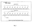
- the architecture of the present invention utilizes the 10 bit countdown timer, which counts sequentially from an arbitrary starting point (which has a maximum value of 1023) to zero. Each counter bit is encoded as a 10-bit sequence, resulting in 100 data bits per count. The total countdown time is found by taking the number of counts multiplied by 100 then divided by the bit rate. As an example, the total time for a full 1024 counts, at a bit rate of 4800 bps, is 21.333 seconds. Counter bits are sent MSB first and the underlying p/n sequence is also sent MSB first, see FIG. 2.
- first network ID 116 and second network ID 118 can constitute data sequences of twenty data bits, thus providing the possibility of hundreds of unique system ID's.
- the logic circuit including a timer, present within the remote first endpoints 106 and the remote second endpoints 110 is preprogrammed to turn on the receiver at selected times.
- the timer can be programmed to turn on the receiver at the top of every hour, every two hours, every three hours, etc.
- the receiver looks to identify the specific network identification to which the receiver component belongs. For example, in the embodiment in which the first network ID 116 and the second network ID 118 comprise unique sequences of ten data bits, the receiver looks to identify either the particular ten data bit sequence or its inverse to verify that data is being actively sought from the AMR network for which the receiver is a component.
- the receiver can identify whether or not its unique network ID is being transmitted by the mobile collection unit 112 or fixed collection unit 114 within twenty data bits. If the receiver fails to identify the unique sequence representing the network ID or its inverse, the logic circuit turns off the meter to avoid further battery consumption.
- a utility will desire information from the remote first endpoints 106 or will desire to transmit information to the remote first endpoints 106.
- remote first endpoints 106 are preprogrammed to include the current date and time.
- the logic circuit will include programming such that the battery powers up the receiver at or just prior to the top of each hour such that the receiver can receive signals being transmitted by the collection unit.
- the collection unit begins transmitting signals at a time just prior to the scheduled power up of the remote first endpoints 106. If communication with the first AMR network 104 is desired, the collection unit will transmit first network ID 116, or its inverse, in a repeating fashion.
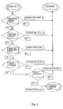
- the remote first endpoint 106 conducts an initial three step inquiry to attempt to verify that the collection unit is attempting to communicate with the first AMR network 104.
- Step 1 the remote first endpoints 106 attempt to identify a sequence of five data bits which correlate to first network ID 116 or its inverse. If a sequence of five such data bits is identified, the data bits are decoded and used in Step 2. If not, the receiver is shut down so as to limit battery usage within remote first endpoint 106.
- Step 2 the five data bits from Step 1 are placed into a ten bit sliding correlator and up to fifteen additional bits are sampled. If a correlation is found between the first network ID 116 or its inverse within the twenty bits, the logic circuit proceeds to Step 3.
- Step 3 the next ten data bits are checked for correlation with the first network ID 116. If there is a correlation, communication between the first AMR network 104 and the collection units can commence in either a true two-way fashion on in a one-way fashion. If there is no correlation, the receiver is shut down.
- the AMR networks can comprise components including sophisticated logic controllers with the capability of conducting true two-way communication with the collection units for purposes of collecting specified data as well as conducting remote updating and configuration of the components.
- the fixed networks can comprise less sophisticated components in which component functions can be related to unique data bit sequences transmitted by the collection units for purposes of collecting specified data or remotely updating and configuring the components.
- first network ID 116 comprises remote first endpoints 106 capable of true two way communication using a ten data bit sequence
- a five step communication progress is depicted in FIG. 2.
- the process includes Steps 1, 2, and 3 wherein confirmation is sought of the transmission of first network ID 116 or its inverse. If first network ID 116 or its inverse is identified, the remote first endpoint 106 proceeds to a Step 4 wherein up to 30 clock bits, or 300 data bits, are decoded by an upper correlator and a lower correlator. If the values in the upper correlator and the lower correlator differ by one, the N,N-1 condition, the remote first endpoint 106 proceeds to Step 5.
- Step 5 the remote first endpoint 106 looks for N-2 in the next ten data bits. If N-2 is found, the remote first endpoint 106 synchronizes itself with the collection unit to turn on at the appropriate time to receive command and control data. In the true two-way communication, remote first endpoint 106 actively converses with the collection unit to communicate data, calibration information or other system information.
- first network ID 116 comprises remote first endpoints 106 capable of one-way communication using a ten data bit sequence
- a four step communication progress is depicted in FIG. 4.
- the process includes Steps 1, 2, and 3 wherein confirmation is sought of the transmission of first network ID 116 or its inverse. If first network ID 116 or its inverse is identified, the remote first endpoint 106 proceeds to a Step 4 wherein up to 30 clock bits, or 300 data bits, are decoded by an upper correlator and a lower correlator.
- Remote first endpoints 106 are preprogrammed such that additional ten data bit sequences represent various tasks to be performed. If the values in these 300 data bits correlate to the preprogrammed data bit sequences or their inverse, the remote first endpoints 106 perform the task and transmit requested information to the collection units.
- the following describes one preferred embodiment for utilizing the sequence inversion keyed countdown timer of the present invention.
- This approach utilizes a simplified head end controller and endpoint for high capacity synchronous data recovery that is capable of accurate time stamping of the data.
- the approach allow for straightforward implementation of multiple message integration techniques because of the known response time of the endpoints. It also allows high capacity cells (more endpoints per controller) with no overhead management for smaller systems if the response slot is based upon the serial number.
- sequence inversion keyed countdown timer is used as the clock to count down to the top of each hour. This requires 24 unique sequences to account for each hour of the day. Alternatively, 12 sequences can be used in conjunction with resetting the endpoint clock every two hours.
- the endpoint is preferably programmed with the current time and date at installation and wakes up approximately 15 seconds prior to the top of the hour to listen for the SIK countdown signal being emitted from the controller.
- the SIK countdown preferably runs from 30 seconds prior to the top of the hour until the top of the hour.
- the endpoint synchronizes its internal clock to the signal at any point during the 30 seconds. Based on the properties of the SIK countdown, the endpoint does not have to listen to the entire sequence to know where the exact top of the hour is located. This approach is very efficient in terms of battery usage because the endpoint is only up and running for about 100 ms per hour.
- the endpoint In normal operation the endpoint has a default slot in which to respond to the system.
- the slots are preferably 250 ms in length and start at the top of the hour and run until 1 minute prior to the next hour mark. Therefore, there will be 30 seconds of dead air time between the start of the time mark and the end of the endpoint data transmissions. This timing allows for 14396 slots per hour. If additional slots are needed the synchronization interval can be extended to two hours and the resulting 28792 slots. This is quite efficient for any low end water utility, apartment complex, or other sub-metering application.
- the endpoint If the endpoint gets lost, i.e., it does not hear the SIK sequence within X hours, the endpoint will come up every 30 seconds to check for the countdown sequence thus automatically re-acquiring the system. Otherwise, the endpoint is only in the receive mode for about 100 ms every hour to resynchronize and about 30 milliseconds to transmit; a battery-friendly approach.
- This specific approach is appropriate for small utilities or micro networks where the full sync and control may be overkill. However, it can utilize the reading technology and software, described in the related applications, without the need for complex head end control.
- the central control unit only has to pick the correct SIK sequence to send out based on time.
- the present invention can be utilized to simplify the head end control and the cost needed for a small utility to implement a fixed network to collect time stamped data on a recurring basis.
Landscapes
- Engineering & Computer Science (AREA)
- Computer Networks & Wireless Communication (AREA)
- Arrangements For Transmission Of Measured Signals (AREA)
- Synchronisation In Digital Transmission Systems (AREA)
- Mobile Radio Communication Systems (AREA)
- Electric Clocks (AREA)
Applications Claiming Priority (4)
| Application Number | Priority Date | Filing Date | Title |
|---|---|---|---|
| US900993 | 1978-04-28 | ||
| US50047903P | 2003-09-05 | 2003-09-05 | |
| US500479P | 2003-09-05 | ||
| US10/900,993 US7372372B2 (en) | 2003-09-05 | 2004-07-28 | Sequence inversion keyed countdown timer utilized within a utility meter system |
Publications (2)
| Publication Number | Publication Date |
|---|---|
| EP1515579A2 true EP1515579A2 (de) | 2005-03-16 |
| EP1515579A3 EP1515579A3 (de) | 2007-08-15 |
Family
ID=34139057
Family Applications (1)
| Application Number | Title | Priority Date | Filing Date |
|---|---|---|---|
| EP04255316A Withdrawn EP1515579A3 (de) | 2003-09-05 | 2004-09-02 | Selbsttätiges Meterablesesystem unter Verwendung von rückwärtszählender Zeitgebervorrichtung |
Country Status (4)
| Country | Link |
|---|---|
| EP (1) | EP1515579A3 (de) |
| JP (1) | JP2005164572A (de) |
| AU (1) | AU2004205349A1 (de) |
| CA (1) | CA2479971C (de) |
Family Cites Families (1)
| Publication number | Priority date | Publication date | Assignee | Title |
|---|---|---|---|---|
| WO1999065169A1 (en) * | 1998-06-09 | 1999-12-16 | Abb Power T & D Company Inc. | Time synchronization of a utility meter via a wireless network |
-
2004
- 2004-08-31 AU AU2004205349A patent/AU2004205349A1/en not_active Abandoned
- 2004-09-01 JP JP2004254121A patent/JP2005164572A/ja active Pending
- 2004-09-01 CA CA002479971A patent/CA2479971C/en not_active Expired - Fee Related
- 2004-09-02 EP EP04255316A patent/EP1515579A3/de not_active Withdrawn
Also Published As
| Publication number | Publication date |
|---|---|
| CA2479971A1 (en) | 2005-03-05 |
| JP2005164572A (ja) | 2005-06-23 |
| CA2479971C (en) | 2009-05-19 |
| AU2004205349A1 (en) | 2005-03-24 |
| EP1515579A3 (de) | 2007-08-15 |
Similar Documents
| Publication | Publication Date | Title |
|---|---|---|
| US7479895B2 (en) | Data communication protocol in an automatic meter reading system | |
| US8786463B2 (en) | Fixed network for an automatic utility meter reading system | |
| US7376118B2 (en) | System and method for optimizing contiguous channel operation with cellular reuse | |
| CA2723665C (en) | Mobile network back-up for fixed meter reading networks | |
| US20050237959A1 (en) | Mobile automatic meter reading system and method | |
| US9529076B2 (en) | Systems and methods for determining locations of wireless sensor nodes in an asymmetric network architecture | |
| JP2018513657A (ja) | 周期的なビーコン信号に基づいて無線センサネットワーク内の通信を提供するためのシステム及び方法 | |
| US9706489B2 (en) | Systems and methods for providing wireless asymmetric network architectures of wireless devices with anti-collision features | |
| AU2006210804B2 (en) | Data communication protocol in an automatic meter reading system | |
| US7372372B2 (en) | Sequence inversion keyed countdown timer utilized within a utility meter system | |
| US9380531B1 (en) | Systems and methods for providing wireless sensor networks with an asymmetric network architecture | |
| WO2016123239A1 (en) | Systems and methods for providing wireless sensor networks with an asymmetric network architecture | |
| US20050086182A1 (en) | Optimized bubble up receiver AMR system | |
| EP1515579A2 (de) | Selbsttätiges Meterablesesystem unter Verwendung von rückwärtszählender Zeitgebervorrichtung | |
| Terada et al. | Enhancement of MAC protocol for power reduction in LoRa WAn | |
| Sousa | Planning smart cities using wireless low energy monitoring systems | |
| KR20140129945A (ko) | 다중 홈 영역 네트워크 환경에서 긴급 메시지 전송 방법 및 시스템 |
Legal Events
| Date | Code | Title | Description |
|---|---|---|---|
| PUAI | Public reference made under article 153(3) epc to a published international application that has entered the european phase |
Free format text: ORIGINAL CODE: 0009012 |
|
| AK | Designated contracting states |
Kind code of ref document: A2 Designated state(s): AT BE BG CH CY CZ DE DK EE ES FI FR GB GR HU IE IT LI LU MC NL PL PT RO SE SI SK TR |
|
| AX | Request for extension of the european patent |
Extension state: AL HR LT LV MK |
|
| PUAL | Search report despatched |
Free format text: ORIGINAL CODE: 0009013 |
|
| AK | Designated contracting states |
Kind code of ref document: A3 Designated state(s): AT BE BG CH CY CZ DE DK EE ES FI FR GB GR HU IE IT LI LU MC NL PL PT RO SE SI SK TR |
|
| AX | Request for extension of the european patent |
Extension state: AL HR LT LV MK |
|
| AKX | Designation fees paid | ||
| REG | Reference to a national code |
Ref country code: DE Ref legal event code: 8566 |
|
| STAA | Information on the status of an ep patent application or granted ep patent |
Free format text: STATUS: THE APPLICATION IS DEEMED TO BE WITHDRAWN |
|
| 18D | Application deemed to be withdrawn |
Effective date: 20080216 |