EP1515548B1 - Bilderfassungssystem und -verfahren zur Anzeige und/oder Aufnahme von unverzerrten Weitwinkelbilddaten - Google Patents
Bilderfassungssystem und -verfahren zur Anzeige und/oder Aufnahme von unverzerrten Weitwinkelbilddaten Download PDFInfo
- Publication number
- EP1515548B1 EP1515548B1 EP04010140.4A EP04010140A EP1515548B1 EP 1515548 B1 EP1515548 B1 EP 1515548B1 EP 04010140 A EP04010140 A EP 04010140A EP 1515548 B1 EP1515548 B1 EP 1515548B1
- Authority
- EP
- European Patent Office
- Prior art keywords
- image data
- wide
- angle
- data
- processor
- Prior art date
- Legal status (The legal status is an assumption and is not a legal conclusion. Google has not performed a legal analysis and makes no representation as to the accuracy of the status listed.)
- Expired - Lifetime
Links
- 238000000034 method Methods 0.000 title description 15
- 238000003384 imaging method Methods 0.000 title description 8
- 230000009466 transformation Effects 0.000 claims description 44
- 238000004364 calculation method Methods 0.000 claims description 8
- 238000012545 processing Methods 0.000 claims description 7
- 238000004422 calculation algorithm Methods 0.000 description 17
- 230000008569 process Effects 0.000 description 8
- 230000001131 transforming effect Effects 0.000 description 6
- 238000010586 diagram Methods 0.000 description 5
- 230000006870 function Effects 0.000 description 5
- 230000001360 synchronised effect Effects 0.000 description 5
- 238000000844 transformation Methods 0.000 description 3
- 230000008901 benefit Effects 0.000 description 2
- 238000013500 data storage Methods 0.000 description 2
- 230000002093 peripheral effect Effects 0.000 description 2
- 230000003068 static effect Effects 0.000 description 2
- 238000003860 storage Methods 0.000 description 2
- PXFBZOLANLWPMH-UHFFFAOYSA-N 16-Epiaffinine Natural products C1C(C2=CC=CC=C2N2)=C2C(=O)CC2C(=CC)CN(C)C1C2CO PXFBZOLANLWPMH-UHFFFAOYSA-N 0.000 description 1
- 230000003139 buffering effect Effects 0.000 description 1
- 238000006243 chemical reaction Methods 0.000 description 1
- 230000000295 complement effect Effects 0.000 description 1
- 239000002131 composite material Substances 0.000 description 1
- 238000012937 correction Methods 0.000 description 1
- 230000003247 decreasing effect Effects 0.000 description 1
- 238000013461 design Methods 0.000 description 1
- 230000008030 elimination Effects 0.000 description 1
- 238000003379 elimination reaction Methods 0.000 description 1
- 210000004209 hair Anatomy 0.000 description 1
- 230000010354 integration Effects 0.000 description 1
- 238000004519 manufacturing process Methods 0.000 description 1
- 238000013507 mapping Methods 0.000 description 1
- 238000007620 mathematical function Methods 0.000 description 1
- 238000005259 measurement Methods 0.000 description 1
- 229910044991 metal oxide Inorganic materials 0.000 description 1
- 150000004706 metal oxides Chemical class 0.000 description 1
- 238000004091 panning Methods 0.000 description 1
- 230000000750 progressive effect Effects 0.000 description 1
- 230000004044 response Effects 0.000 description 1
- 239000004065 semiconductor Substances 0.000 description 1
- 230000002123 temporal effect Effects 0.000 description 1
- 230000000007 visual effect Effects 0.000 description 1
Images

Classifications
-
- H—ELECTRICITY
- H04—ELECTRIC COMMUNICATION TECHNIQUE
- H04N—PICTORIAL COMMUNICATION, e.g. TELEVISION
- H04N5/00—Details of television systems
- H04N5/222—Studio circuitry; Studio devices; Studio equipment
- H04N5/262—Studio circuits, e.g. for mixing, switching-over, change of character of image, other special effects ; Cameras specially adapted for the electronic generation of special effects
- H04N5/2628—Alteration of picture size, shape, position or orientation, e.g. zooming, rotation, rolling, perspective, translation
-
- H—ELECTRICITY
- H04—ELECTRIC COMMUNICATION TECHNIQUE
- H04N—PICTORIAL COMMUNICATION, e.g. TELEVISION
- H04N23/00—Cameras or camera modules comprising electronic image sensors; Control thereof
- H04N23/58—Means for changing the camera field of view without moving the camera body, e.g. nutating or panning of optics or image sensors
-
- H—ELECTRICITY
- H04—ELECTRIC COMMUNICATION TECHNIQUE
- H04N—PICTORIAL COMMUNICATION, e.g. TELEVISION
- H04N23/00—Cameras or camera modules comprising electronic image sensors; Control thereof
- H04N23/60—Control of cameras or camera modules
- H04N23/698—Control of cameras or camera modules for achieving an enlarged field of view, e.g. panoramic image capture
-
- H—ELECTRICITY
- H04—ELECTRIC COMMUNICATION TECHNIQUE
- H04N—PICTORIAL COMMUNICATION, e.g. TELEVISION
- H04N7/00—Television systems
- H04N7/18—Closed-circuit television [CCTV] systems, i.e. systems in which the video signal is not broadcast
- H04N7/181—Closed-circuit television [CCTV] systems, i.e. systems in which the video signal is not broadcast for receiving images from a plurality of remote sources
Definitions
- This invention generally relates to imaging systems, and more particularly, to a system and method for generating undistorted image data, such as video signals suitable for display and/or recording by conventional equipment, from wide-angle lens image data.
- Conventional video surveillance systems allow users to view portions of monitored areas by either physically aiming a video camera at a desired portion or by generating a perspective corrected view of the desired portion from a wide-angle (e.g., fisheye) image of the monitored area.
- Signals from the video camera are typically decoded into digital video data.
- the data is then buffered for processing.
- processing may entail performing complex mathematical transformations to remove wide-angle distortion.
- As the data is transformed it is typically sent to an output buffer before it is encoded for output to a display or recorder.
- Such conventional systems have several shortcomings.
- RISC Reduced Instruction Set Computer
- CISC Complex Instruction Set Computer
- Transformation algorithms typically require performance of many floating point, trigonometric and division operations, as well as other complex mathematical functions that consume appreciable processor resources and time.
- US 5,903,319 discloses a method and apparatus for the elimination of temporal and spatial distortions from interlaced video signals, particularly those that occur in signals associated with affine transformations.
- a system for correcting wide-angle image data, wherein the system comprises a first input buffer configured to store wide-angle image data, an image data processor operably coupled to said first buffer and configured to transform wide-angle image data stored in the first input buffer into corrected image data, an encoder operably coupled to said image data processor and configured to receive and encode the corrected image data in a format suitable for at least one of display and recording of corrected images and wherein corrected image data is not stored in a buffer from the time of transformation by the image data processor until the time said undistorted image data is received by the encoder.
- EP 1 028 389 A2 discloses an arithmetic unit for image transformation, especially for transforming a fisheye image obtained by using a fisheye lens into a plane image for display.
- the unit comprises a first coordinate calculating unit for obtaining first projection coordinates derived by projecting coordinates on the plane image onto a fisheye image face as an imaginary object face; and a second coordinate calculating unit for obtaining second projection coordinates derived by projecting the first projection coordinates obtained by the first coordinate calculating unit onto the fisheye image face
- US 2002/0102101 A1 discloses a camera system that comprises a stationary camera having a wide angle view, a remotely controllable camera having a relatively smaller angle view for providing images in substantially full resolution, and a processor.
- the invention avoids the drawbacks and disadvantages of the prior art by providing a system for correcting wide-angle image data according to Claim 1.
- the system may generate a graphical user interface that provides a plurality of substantially undistorted views from the wide-angle image data, including, for example, a panoramic view that provides a substantially undistorted view based on the wide-angle image data, a virtual view corresponding to a portion of the panoramic view based upon wide-angle data or other image data, and a display reference window overlaid in a panoramic view to identify the portion of a panoramic view represented by the virtual view.
- the system may include a dome camera system configured to provide image data for a virtual view according to commands. The dome camera image data may exhibit higher resolution than the wide-angle data.
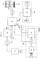
- An imaging system constructed in accordance with the principles of the invention includes components configured to transform digital image data corresponding to wide-angle images, such as video images, of a monitored area into data corresponding to one or more undistorted (or substantially undistorted) views of the monitored area that may be displayed on conventional closed circuit television (“CCTV") monitors without use of a post-transformation output image buffer.
- Wide-angle image data may be transformed as needed for encoding and output.
- image sources may supply image data for use by a system in accordance with the invention.
- one or more imagers such as digital or analog video cameras may be used to supply video data, which may be in any known format.
- video broadly refers to images, such as images of stationary and/or moving objects, which may or may not be produced using signals in known formats, such as NTSC signals.
- the system of the invention may operate in real time, processing video data as it is produced using the video imagers and without appreciably delaying output to a display monitor or recorder.
- the video imaging system 100 includes a video camera 110 equipped with a wide-angle lens 105, such as a fisheye lens.
- a wide-angle lens 105 such as a fisheye lens.
- Various wide-angle lenses are available, many of which, for example, have an angular field of view of approximately 75 degrees or more.
- the wide-angle lens 105 may preferably be suitable for producing an image of an entire area to be monitored (e.g., portions of a room excluding the ceiling) when the wide-angle lens is positioned at a determined point relative to the monitored area (e.g., on a ceiling of the room, at or near the center of the ceiling, pointing downwardly).
- a fisheye lens which is a type of wide-angle lens 105, and which may have a field of view of 180 degrees
- the camera 110 may employ a charge coupled device (CCD) array, a Time Delay Integration (TDI) CCD array, complementary metal oxide semiconductor (CMOS) image sensors or other sensors or devices for electronic image production. Additionally, the camera 110 may be a digital or analog camera.
- CCD charge coupled device
- TDI Time Delay Integration
- CMOS complementary metal oxide semiconductor
- the camera 110 may be a digital or analog camera.
- wide-angle lenses 105 are useful for capturing a wide field of view, they tend to distort images by curving or warping objects. Such curving or warping, also known as barrel distortion, is referred to herein as “distortion”, “wide-angle lens distortion” or the like. Typically, the wider the field of view for a lens, the more pronounced the distortion will be.
- undistorted means without any, or with substantially reduced, wide-angle image distortion.
- Undistorted data is produced by transforming wide-angle image data using mathematical algorithms, as discussed more fully below.
- An “undistorted image” is an image produced using "undistorted data.”
- the wide-angle lens 105 is aimed at the area to be monitored.
- the lens 105 may be a fisheye lens or another type of wide-angle lens that provides a 180 degree field of view, or a wider or narrower field of view.
- the lens may be a fisheye lens positioned on a ceiling near the center of a monitored room, aimed downwardly. This position and orientation may generate a view of substantially the entire monitored room, excluding the ceiling.
- a video decoder 115 operably coupled to the camera 110 translates analog signals from the camera 110 into digital video data.
- the decoder 115 includes a clock circuit (e.g., a 27 MHz video clock circuit) suitable for synchronization and processing of video image data streams.
- Clock signals 117 from the clock circuit are transmitted to processor 125.
- a suitable decoder 115 may include commercially available decoders, such as an SAA7113H 9-bit video input processor available from Phillips Electronics N.V.
- the SAA7113H 9-bit video input processor includes an anti-aliasing filter, an automatic clamp and gain control, a clock generation circuit, a digital multi-standard decoder, and a brightness, contrast and saturation control circuit.
- Decoder 115 may be able to decode Phase Alternation Line (PAL), French Sequential Couleur Electro Memoire (SECAM) and American National Television Systems Committee (NTSC) standard signals into CCIR-601 (International Radio Consultative Committee, now the International Telecommunication Union Radiocommunication Sector, standard for encoding analog video signals in digital form) compatible color component data values.
- the SAA7113H 9-bit video input processor accepts as analog inputs CVBS (i.e., composite Chroma Video Blanking & Sync inputs) or S-video (Y/C).
- CVBS i.e., composite Chroma Video Blank
- Digital video data from decoder 115 is stored in an input image buffer 120.
- the input image buffer 120 may be comprised of volatile or non-volatile memory or other devices configured to store video image data.
- the data may be stored temporarily, for example, until no longer needed for transformation by the image data processor 125, as described below, until new video image data is required to be stored in the occupied portion of the buffer, or until some other event occurs or a determined period of time elapses.
- the buffer 120 may be sized to store image data corresponding to an entire field or frame of video, or more or less data.
- One or more user input modules 190 may also be provided to generate user commands.
- the module 190 may include an input device 175 such as a keypad, digitizer, joystick, microphone and voice recognition module, or some other device configured to enable a user to enter commands.
- the input device 175 may be operably coupled to an input processor 180 and input memory 185 configured to produce user command data 192 corresponding to user input commands.
- the input processor 180 may be implemented as a special purpose computer; a programmed general purpose computer; a programmed microprocessor, microcontroller or programmable read-only memory and peripheral integrated circuit elements; an application specific integrated circuit (ASIC) or other integrated circuits; a digital signal processor; a hardwired electronic or logic circuit such as a discrete element circuit; and/or a programmable logic device such as a field programmable gate array (FPGA), or the like.
- ASIC application specific integrated circuit
- FPGA field programmable gate array
- the input memory 185 may include volatile or non-volatile memory such as, for example, static random access memory (SRAM), dynamic random access memory (DRAM), fast page mode dynamic random access memory (FPM DRAM), extended data-out dynamic random access memory (EDO DRAM), synchronous dynamic random access memory (SDRAM), double data rate synchronous dynamic RAM (DDR SDRAM), electronically erasable programmable read only memory (EEPROM) such as flash memory with or without a controller, hard disk enabled virtual memory, and/or other data storage devices that may be operably coupled to the input processor 180.
- SRAM static random access memory
- DRAM dynamic random access memory
- FPM DRAM fast page mode dynamic random access memory
- EEO DRAM extended data-out dynamic random access memory
- SDRAM synchronous dynamic random access memory
- DDR SDRAM double data rate synchronous dynamic RAM
- EEPROM electronically erasable programmable read only memory
- flash memory with or without a controller, hard disk enabled virtual memory, and/or other data storage devices that may be operably coupled to the input processor
- calculations that are required for transformation may be calculated using the input module 190. Delegating such computations to the input module may help conserve image data processor 125 resources and facilitate real-time transformations.
- An image data processor 125 may receive buffered image data 122, clock signals 117 and user command data 192 to produce undistorted data.
- the processor 125 may be implemented as a special purpose computer; a programmed general purpose computer; a programmed microprocessor, microcontroller or programmable read-only memory and peripheral integrated circuit elements; an application specific integrated circuit (ASIC) or other integrated circuits; a digital signal processor; a hardwired electronic or logic circuit such as a discrete element circuit; and/or a programmable logic device such as a field programmable gate array (FPGA), or the like.
- a preferred implementation uses an FPGA or an ASIC as the processor 125. When a system design is considered stable, an FPGA could be replaced with an ASIC to reduce system cost.
- the image data processor 125 may also be operably coupled to memory 130, which may, for example, be non-volatile memory comprised of electronically erasable programmable read only memory (EEPROM), such as flash memory; a solid-state floppy-disk card (SSFDC) such as SmartMedia ® memory commercially available by Kabushiki Kaisha Toshiba, Toshiba Corporation, and Toshiba America Electronic Components, Inc.; CompactFlash ® memory by SanDisk Corporation; hard disk enabled virtual memory; and/or other non-volatile storage devices.
- memory 130 may be used to facilitate processor computations by storing one or more tables of values for frequently calculated functions, especially functions that might otherwise consume significant processor 125 resources.
- memory 130 may store a table of values, such as cosine, sine, 1/cosine, 1/sine, or other values based on trigonometric or other types of functions used in an applicable transformation algorithm, as discussed more fully below.
- the indices for the table may be angular values in degrees, radians, other types of measurements, or some other possible value for a variable.
- the table entries may be pre-calculated values based on the corresponding indices. Trigonometric functions and complex floating point calculations can otherwise be a time and resource consuming part of processor 125 calculations.
- the use of pre-determined stored values conserves processor resources and may lead to an appreciable increase in overall transformation speed.
- the image data processor 125 mathematically transforms wide-angle image data in the input image buffer 120 into undistorted data using a transformation algorithm.
- the image data processor 125 is configured to complete transformation calculations, on a pixel-by-pixel basis, as the data for a pixel is needed for encoding to produce output video signals in real-time. Transformation calculations are started far enough in advance such that the final calculation step is completed just in time to provide undistorted image data to the encoder.
- one NTSC video frame displayed approximately every 1/30 th of a second, contains two interlaced fields. Each field is displayed approximately every 1/60th of a second each.
- a system made in accordance with the principles of the invention may generate all undistorted pixel image data for a frame approximately every 1/30 th of a second.
- the time may be monitored using the 27 MHz clock circuit signals 117.
- an interlaced NTSC display of 720 by 486 pixels and a refresh rate of 60 Hz must display all the pixels for a field (i.e., 174,960 pixels) approximately every 1/60 th of a second, or a pixel must be generated approximately every 9.526 x 10 -8 seconds.
- the processor 125 Upon transformation, the processor 125 sends transformed video data to an encoder 135.
- the encoder 135 converts the digital video data into output signals compatible with an output device such as a standard CCTV display monitor 140 and/or video recorder 145.
- the monitor 140 may display a graphical user interface such as that described in the discussion of Figure 2 .
- the encoder 135 may be any suitable commercially available decoder, such as an SAA7121H digital video encoder by Phillips Electronics, N.V.
- the SAA7121H digital video encoder circuit accepts CCIR compatible YUV data with 720 active pixels per line and encodes the digital YUV video data to NTSC, PAL, CVBS or S-video signals.
- Output from the encoder 135 is sent to an output device, such as a standard CCTV display monitor 140 and/or video recorder 145.
- the display monitor 140 a device configured to visually display images based on electronic video signals output from the encoder 135.
- the recorder 145 may be any device configured to record video signals from the encoder 135 on removable or non-removable storage media such as, for example, a magnetic tape, diskette, CD-ROM, DVD, hard disk, memory (e.g., nonvolatile EEPROM) or the like. If both a display monitor 140 and recorder 145 are used, the devices may be configured in parallel or in series (e.g., without output from the video recorder being sent to a display monitor).
- the image data processor 125 in addition to transforming wide-angle image data, produces output image data from one or more supplementary sources, such as an additional camera system 150.
- the additional camera system 150 includes an analog or digital camera 160 with a normal lens 155 (i.e., not a wide-angle lens) aimed at a determined portion of the monitored area.
- the lens 155 may have a narrower Field of View (FOV), e.g., 45°, which would provide higher resolution than wide-angle lens 105, thus providing a more detailed video image.
- FOV Field of View
- Such a configuration may also enable switching from a relatively low resolution undistorted image derived from wide-angle lens image data to a higher resolution image, with a higher zoom factor capability, produced using the additional camera system. This gives the user the ability to isolate small details of a monitored area.
- the additional camera system 150 may also include a video decoder 165 that is operably coupled to the camera and configured to translate analog signals from the camera into digital video data.
- the decoder 165 may also include a clock circuit (e.g., a 27 MHz video clock circuit) suitable for synchronization and processing of video image data streams.
- Clock signals 167 may be transmitted to processor 125.
- the additional camera system 150 further includes an image buffer 170.
- the image buffer 170 may be comprised of volatile or non-volatile memory or other devices configured to temporarily store video image data, such as, for example, static random access memory (SRAM), dynamic random access memory (DRAM), fast page mode dynamic random access memory (FPM DRAM), extended data-out dynamic random access memory (EDO DRAM), synchronous dynamic random access memory (SDRAM); double data rate synchronous dynamic RAM (DDR SDRAM), Rambus dynamic random access memory (RDRAM), multiport dynamic random access memory (MPDRAM), synchronous graphics RAM (SGRAM), electronically erasable programmable read only memory (EEPROM), hard disk enabled virtual memory and/or other data storage device.
- SRAM static random access memory
- DRAM dynamic random access memory
- FPM DRAM fast page mode dynamic random access memory
- EEO DRAM extended data-out dynamic random access memory
- SDRAM synchronous dynamic random access memory
- DDR SDRAM double data rate synchronous dynamic RAM
- RDRAM Rambus dynamic random access memory
- the buffer 170 may be sized to store image data corresponding to an entire field or frame of video, or more or less data.
- Buffered video data 172 may be transmitted to processor 125. That data may then be processed and encoded 135 for output to a display or recording device.
- the additional camera system 150 may be configured as a programmable dome camera system. Dome cameras can typically rotate (i.e., pan) 360 degrees, and tilt and zoom according to control signals.
- Processor 125 may produce control data 194, based upon user command data 192 from user input module 190, to control positioning and movement of the dome camera.
- a control interface (not shown) may also be operably coupled to dome camera 160 and processor 125, as necessary to convert control data output from the processor 125 into signals for controlling dome camera 160 position, movement and zooming.
- Undistorted data may be produced by mathematically transforming wide-angle image data.
- Many transformation processes also referred to as dewarping, mapping, remapping, planar projection, conversion and perspective correction
- dewarping, mapping, remapping, planar projection, conversion and perspective correction are known in the art and can be adapted, in accordance with the teachings herein, to produce undistorted data from wide-angle image data (including fisheye image data). While the invention is not limited to any specific transformation processes, an exemplary panoramic view transformation and an exemplary virtual view transformation are described more fully below for use with a system of the invention employing fisheye lens image data.
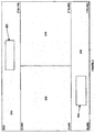
- Strips which may be rectangular in shape as illustrated, correspond to transformed panoramic views.
- the transformed panoramic views 210 and 260 exhibit upright orientation and substantially reduced (or no) wide-angle image distortion, thus providing a readily discernible view of the monitored area.
- An example of a suitable transformation carried out by the processor is discussed subsequently.
- Virtual view data may be obtained either by transformation of portions of the wide-angle video image data, or by positioning and focusing a camera having a normal lens (i.e., not a wide-angle lens) to produce image data for the determined portion of the monitored area. Again, a suitable exemplary transformation to obtain the virtual view data is discussed subsequently.
- the processor may be further configured to provide reference overlay (e.g., windows - i.e., graphically generated frames or boxes, or other shapes, overlaid in the panoramic views - frames 220 and 250 as shown in Figure 2 ) corresponding to the undistorted view of the determined portions of the panoramic views represented by the virtual views 230 and 240.
- reference overlay e.g., windows - i.e., graphically generated frames or boxes, or other shapes, overlaid in the panoramic views - frames 220 and 250 as shown in Figure 2
- the reference overlay 220 and 250 reveals what portions of the panoramic views are represented by the virtual views 230 and 240.
- the corresponding reference window 220 or 250 overlaid on top of a panoramic view 210 and 260 is adjusted by moving and/or changing its size in the panoramic view 210 or 260, to conform to the virtual view, thus indicating the part of the panoramic view 210 and 260 represented by the virtual view 230 or 240.
- Panning and tilting a virtual view 230 or 240 causes the reference window 220 or 250 to move horizontally and/or vertically in a panoramic view 210 or 260.
- Zooming in i.e., increasing zoom
- Zooming out i.e., decreasing zoom
- the system is preferably configured to allow a user to select which virtual view 230 or 240 to currently control.
- the active (i.e., currently controlled) virtual view 230 or 240 may be distinguished from the inactive virtual view by an indicia. For example, a white frame may surround the active virtual view and a black frame may surround the inactive virtual view.
- the corresponding reference window 220 or 250 may also be highlighted in either black or white based on its associated virtual view's active/inactive status.
- the exemplary display screen may have a resolution of 720 by 486 pixels.
- the exemplary panoramic views, as shown in Figure 2 are each 720 pixels wide and 120 pixels high.
- the exemplary virtual views, as shown in Figure 2 may each be 360 pixels wide and 246 pixels high.
- Those skilled in the art will appreciate that the invention is not limited to the exemplary resolution or view sizes. Many other resolutions and sizes are feasible and come within the scope of the invention.
- the reference overlay (e.g., reference windows 220 and 250 ) in an exemplary implementation conforms to virtual view 230 and 240 positioning and zooming.
- a user may pan, tilt and zoom virtual view 230 and 240 to represent any portions of the panoramic views 210 and 260.
- the portions of the panoramic views represented by the virtual view 230 and 240 define the areas overlaid by reference windows 220 and 250.
- Other manifestations of reference overlay such as numerical coordinates or cross hairs, may be used in lieu of or in addition to reference windows 220 and 250.
- the system may be configured to automatically determine the portions of the panoramic views 210 and 260 to cover, such as by one or more determined algorithms (e.g., move reference windows as a function of time) or in response to one or more signals (e.g., a motion detector, gate sensor, or alarm signal).
- determined algorithms e.g., move reference windows as a function of time
- signals e.g., a motion detector, gate sensor, or alarm signal
- Panoramic views 210 and 260 and virtual views 230 and 240 are displayed concurrently on a display monitor, thus providing a readily discernible view of the entire monitored area and an undistorted view of a portion of the monitored area.
- the reference overlay 220 and 250 may also be displayed with the panoramic views 210 and 260, thus enabling a user to readily identify the portions of the panoramic views 210 and 260 that are represented by the virtual views 230 and 240.
- the invention is not limited to the exemplary number, size, shape or arrangement of views shown in Figure 2 and discussed above.
- one or more panoramic views 210 and 260, and/or virtual views 230 and 240 and reference windows 220 and 250 may be provided within the scope of the invention.
- a display may show one or more undistorted images produced from wide-angle image data, without departing from the scope of the invention.
- the user interface components may be arranged as shown in Figure 2 and discussed above.
- the interface may be configured to allow a user to control the display arrangement.
- a user may hide or move a panoramic view 210 or 260, and/or a virtual view 230 or 240 and/or a reference window 220 or 250; or hide all virtual views 230 and 240 reference windows 220 and 250; or opt to display only a selected panoramic view 210 or 260 or virtual view 230 or 240.
- the exemplary panoramic view transformation process involves mathematically transforming wide-angle video image data into 2-dimensional space for producing panoramic views.
- the exemplary transformation entails determining, for each output window pixel coordinate, an address within the image buffer 120 for pixel data to be encoded and output to a display and/or recorder 145.
- this address calculation is timed such that the calculated address for each output pixel is ready just in time to feed the output encoder. This implementation advantageously eliminates the need for an output image buffer.
- two panoramic views 210 and 260 may be produced.
- One panoramic view 210 corresponds to half of the monitored area (e.g., a 0-180 degree panoramic view strip).
- the other panoramic view corresponds to the other half of the monitored area (e.g., a 181-360° panoramic view strip).
- the second panoramic view is offset from the first panoramic view by half of the field of view.
- the points dividing one half from the other half may be pre-programmed, user configurable or user controllable.
- the two panoramic views combined provide a full (e.g., a 360°) view of the monitored area.
- the exemplary panoramic views are 720 pixels wide and 120 pixels high.
- Output window pixel coordinates range from -360 to +360 for Wx and from -60 to +60 for Wy.
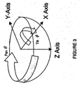
- the Wx and Wy coordinates are derived from the output view column and line pixel counters, and together with the desired Zoom factor, are transformed into ⁇ (i.e., the pan rotation angle around the Z-axis) and ⁇ (the tilt rotation angle around the X-axis), as conceptually illustrated in Figure 3 .
- This information is then converted to an address in the input capture buffer.
- the data from this address is output to the encoder for display.
- the variables Pan, Tilt and Zoom may be programmed or commanded via user input module 190. Given:
- the horizontal component of the panoramic view (starting with output window upper left at -360, +120) is converted from pixel units to degrees (SFx). Each output pixel equates to .25 degrees (180°/720 pixels). The programmable Pan value is added to each pixel value.
- the second panoramic view 260 is offset from the first 210 by +180 degrees.
- the vertical component of the panoramic view (starting with output window upper left at origin -360, +120) is converted from pixel units to degrees (SFy). Each vertical pixel equates to 0.375 degrees (45°/120lines).
- the programmable Tilt value is added to each pixel value.
- the programmable zoom performs a scale (45° x (1/zoom)) / 120. Therefore, Zoom Scale equals 1.
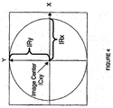
- Ix Radius ⁇ cos ⁇ ⁇ IRx + ICx
- Iy Radius ⁇ sin ⁇ ⁇ IRy + ICy
- the image buffer 120 is preferably addressed as a 1024 byte by 1024 byte array.
- Pixel Data may then be sent to the encoder 135 for output to the output device such as a display monitor 140 and or a recorder 145. Pixel Data for each pixel comprising the panoramic views 210 and 260 may be determined in a similar manner.
- Each virtual view window 230 and 240 provides a perspective corrected view (e.g., a view with no, or substantially reduced, fisheye distortion) of any portion of a panoramic view 210 or 260.
- the virtual view windows are preferably 360 pixels wide and 240 pixels high. The center of the window is defined as 0,0.
- Wx values range from -180 to +180 and Wy values range from +120 down to -120.
- the Wx and Wy coordinates are taken from the output window line and pixel counters and, together with the desired Pan, Tilt and Zoom Scale, are transformed into ⁇ , ⁇ , and Radius using the virtual view transformation algorithm.
- the processor determines which algorithm (i.e., the virtual view transformation algorithm or the panoramic view transformation algorithm) to use based on where the counters indicate it is in the output video frame.
- ⁇ is defined as the Pan angle around the Z-Axis, where the positive Y direction, as shown in Figure 3 , is 0 degrees.
- ⁇ is the Tilt angle around the X-Axis where the positive Z direction, pointing straight down as shown in Figure 3 , is 0 degrees.
- Z is the perpendicular distance from the X-Y plane down to the surface of a unity radius hemispheric fisheye model.
- the virtual view transformation algorithm entails converting the X and Y output window coordinates to an equivalent proportion of a unity radius hemisphere model using a current Zoom factor and a measured radius-X and radius-Y from an input fisheye circular image. These adjusted values are used to calculate a corresponding Z value.
- the X, Y and Z coordinates are rotated around the unity radius hemisphere model using the commanded Pan and Tilt from the user input module 190.
- the rotated X and Y values are then rescaled back to pixels and lines, based on measured radius-X and radius-Y from the input fisheye circular image.
- the rescaled X and Y are then converted to an address in the input image buffer 120. Data from this address is then output to the encoder 135 for display.
- the variables Pan, Tilt, and Zoom are the angle of interest commanded by the user input module 190. Given:
- the vertical and horizontal components of the virtual view window (center at origin 0,0) are converted from pixel units to unit values from 0 to less than one by dividing the pixel number by the respective image radius.
- One is the maximum length from the center of the virtual output image, to the edge of the image.
- the desired radius squared is calculated from the vertical and horizontal components using the Pythagorean theorem.
- Wr 2 Wx 2 + Wy 2
- a rotation of the desired window to a desired spot on the image can be performed using the Pan and Tilt values to simulate a movable dome.
- Iz ⁇ Iz ⁇ cos Tilt ⁇ Wy ⁇ sin Tilt
- Wy ⁇ Wy ⁇ cos Tilt + Iz ⁇ sin Tilt
- Ix Wx ⁇ ⁇ IRx
- Iy Wy ⁇ ⁇ IRy
- the image buffer 120 may be addressed as a 1024 byte by 1024 byte array.
- PixelData may then be sent to the encoder 135 for output to the display window.
- the panoramic views 210 and 260 provide context for the virtual views 230 and 240.
- a user never loses sight as to what is happening in the monitored area outside a virtual view, even as the user zooms in on a specific event or object.
- the user does not have to keep changing video sources to view areas outside the virtual views 230 and 240.
- the reference windows 220 and 250 provide a visual indication of the portion of a panoramic view represented by a virtual view.
- a user can readily determine where in a monitored area they are looking.
- the ability to switch to the additional camera to produce a high resolution, high zoom factor, virtual view gives the user the ability to resolve small details of a scene.
- transformation algorithms may be used for transforming wide-angle image data according to the principles of the invention.
- various factors may come into play, including, for example, available system resources (e.g.; processor type and speed, and memory), cost, speed and output quality.
- an algorithm may be better suited for one system configuration over another system configuration.
- a system intended for a particular purpose e.g., a high resolution progressive display, may benefit more from or demand a fast algorithm to generate the required undistorted pixel data in a timely manner.
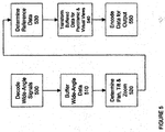
- FIG. 5 a high level flow chart illustrating a process for producing an undistorted image not in accordance with an exemplary implementation of the invention is shown. The steps may be implemented using a system with a programmed processor as described above. Figure 5 may equally represent a high level block diagram of an exemplary system not constructed in accordance with the invention, implementing the steps thereof.
- step 500 wide angle image signals are decoded into digital wide-angle image data.
- the signals may be supplied from a video camera system or from a source of prerecorded data.
- step 510 the decoded wide-angle data (e.g., fisheye lens image data) is buffered. Buffering entails storing the data in an input image buffer.
- pan, tilt and zoom data are obtained to specify regions of interest from the buffered wide-angle data for display.
- Pan, tilt and zoom data may be supplied via a user input module, such as user input module 290.
- a user input module such as user input module 290.
- values other than pan, tilt and zoom e.g., Cartesian coordinate values may be specified to define areas of interest in the panoramic views.
- step 540 buffered wide-angle data are transformed using a transformation algorithm.
- the wide-angle image data is transformed, on a pixel-by-pixel basis, as the data for a pixel is required for encoding, to produce output signals in real-time.
- the transformation may, for example, be carried out according to a transformation process as described above.
- step 550 as data is transformed in step 540, the transformed data is encoded for output.
- the encoded output may then be sent to a display monitor and/or to a recorder.
- a pre-programmed pan, tilt and zoom may be determined before wide-angle data is initially buffered.
- FIG. 6 a high level flow chart illustrating another process for producing an undistorted image not in accordance with an exemplary implementation of the invention is shown. As with the process illustrated by the flowchart of Figure 5 , the steps may be implemented using a system with a programmed processor as described above. Figure 6 may equally represent a high level block diagram of an exemplary system constructed in accordance with the invention, implementing the steps thereof.
- step 610 wide-angle image signals are decoded into digital wide-angle image data.
- the signals may be supplied from a video camera system or from a source of prerecorded data.
- step 615 the decoded wide-angle image data (e.g., fisheye lens image data) is buffered.
- buffered wide-angle data are transformed, for example, using a panoramic transformation algorithm for panoramic view data, and using a virtual view transformation algorithm for virtual view data.
- the wide-angle image data are transformed, on a pixel-by-pixel basis, as the data for a pixel is required for encoding, to produce output signals in real-time.
- the transformation may, for example, be carried out according to a transformation process as described above.
- dome camera positioning signals may be obtained from user input, such as user input of pan, tilt and zoom data or commands.
- the communicated positioning signals will cause the dome camera to aim at and zoom to the region of the monitored area corresponding to the determined pan, tilt and zoom values.
- values other than pan, tilt and zoom e.g., Cartesian coordinate values
- dome camera signals are decoded into digital dome camera image data.
- the signals are supplied from a dome camera system.
- the decoded dome camera image data is buffered.
- the buffered dome camera data may be encoded, without transformation, for output to a display monitor and/or to a recorder.
- step 640 coordinates are determined for overlaying a reference window in a panoramic view.
- the overlaid reference window which is generated in step 645, reveals the portion of a panoramic view represented by a virtual view.
- step 650 buffered dome camera data, buffered wide-angle data, and data corresponding to a reference window are combined.
- the combined transformed wide-angle data, dome camera data and pixel data corresponding to the reference window are encoded, as in step 660.
- the dome camera data may defines a virtual view.
- the transformed data may define another virtual view and panoramic views.
- the pixel data corresponding to the reference window defines a reference window.
- the encoded output may be sent to a display monitor and/or to a recorder.
- the reference overlay coordinates may be determined before, after or during transformation of the buffered data.
- a pre-programmed pan, tilt and zoom may be determined before the wide-angle data is initially buffered.
- dome position data may be sent before reference overlay is determined.
- dome data may be buffered after transformation of wide-angle data.
- dome camera data may be obtained by the processor before completion of transformation. Additionally, various steps may be performed concurrently.
Landscapes
- Engineering & Computer Science (AREA)
- Multimedia (AREA)
- Signal Processing (AREA)
- Image Processing (AREA)
Claims (6)
- System (100) zum Korrigieren von Weitwinkelbilddaten, das System aufweisend:einen ersten Eingangszwischenspeicher (120), der zum Speichern von Weitwinkelbilddaten konfiguriert ist;einen Bilddatenprozessor (125), der betriebsfähig an den ersten Eingangszwischenspeicher (120) gekoppelt und zum Umwandeln von Weitwinkelbilddaten (122), die im ersten Eingangszwischenspeicher (120) gespeichert sind, in korrigierte Bilddaten konfiguriert ist; wobeidie Weitwinkelbilddaten Verzerrung enthalten und der Bilddatenprozessor (125) die Weitwinkelbilddaten im ersten Eingangszwischenspeicher (120) in korrigierte Bilddaten umwandelt, die im Wesentlichen unverzerrt sind;eine erste Quelle von Weitwinkelbilddaten, die betriebsfähig an den ersten Eingangszwischenspeicher (120) gekoppelt ist, wobeidie erste Quelle von Weitwinkelbilddaten eine Videokamera (110) ist, die mit einer Weitwinkellinse (105) ausgerüstet ist, wobei die Weitwinkellinse (105) auf einen Bereich gerichtet ist, der überwacht werden soll;einen Codierer (135), der betriebsfähig an den Bilddatenprozessor (125) gekoppelt ist und zum Empfangen und Codieren der korrigierten Bilddaten in ein Format konfiguriert ist, das zu mindestens einem von Anzeigen und Aufzeichnen von korrigierten Bildern geeignet ist; wobeidie korrigierten Bilddaten ab der Zeit der Umwandlung durch den Bilddatenprozessor (125) bis zu der Zeit, zu der die unverzerrten Bilddaten durch den Codierer (135) empfangen werden, nicht in einem Zwischenspeicher gespeichert werden; undeinen Monitor (140), der zum Anzeigen von korrigierten Bildern betriebsfähig an den Codierer (135) gekoppelt ist, wobei der Monitor (140) ein Gerät ist, das zum visuellen Anzeigen von Bildern auf Grundlage von elektronischen Videosignalen, welche vom Codierer (135) ausgegeben werden, konfiguriert ist, wobei die Ausgabe vom Codierer (135) an den Monitor (140) gesendet wird,wobei der Codierer ferner zum Ausgeben von Signalen zum Erzeugen von korrigierten Bildern, die mehrere Pixel aufweisen, konfiguriert ist; undwobei der Bilddatenprozessor (125) zum Umwandeln von Weitwinkelbilddaten (122), die im ersten Eingangszwischenspeicher (120) gespeichert sind, in unverzerrte Bilddaten durch Bestimmen, für jedes der mehreren Pixel, von Weitwinkelbilddaten, die jedem der mehreren Pixel auf einer Pixel-für-Pixel-Basis entsprechen, und Zuführen der Weitwinkelbilddaten zum Codierer (135) konfiguriert ist, dadurch gekennzeichnet, dassdas System (100) ferner Folgendes umfasst:einen zweiten Eingangszwischenspeicher (170), der zum Speichern von Bilddaten konfiguriert ist, die sich von den Weitwinkelbilddaten unterscheiden, welche im ersten Eingangszwischenspeicher (120) gespeichert sind, wobei der zweite Eingangszwischenspeicher betriebsfähig mit dem Bilddatenprozessor (125) verbunden ist, undmindestens ein zusätzliches Kamerasystem (150), das eine zweite Quelle von Normalsehfeldbilddaten umfasst und betriebsfähig an den zweiten Eingangszwischenspeicher (170) gekoppelt ist;wobeidas zusätzliche Kamerasystem (150) eine Analog- oder Digitalkamera (160) mit einer normalen Linse (155) enthält, die auf einen bestimmten Abschnitt des überwachten Bereichs gerichtet ist; wobeider Bilddatenprozessor (125) ferner zum Erzeugen von Ausgabebilddaten vom zusätzlichen Kamerasystem (150) konfiguriert ist, wodurch das gleichzeitige Anzeigen eines unverzerrten Bilds, das aus umgewandelten Weitwinkelbilddaten abgeleitet ist, und eines Bilds, das unter Verwendung des zusätzlichen Kamerasystems (150) erzeugt ist, auf dem Monitor (140) ermöglicht ist.
- System (100) nach Anspruch 1, ferner aufweisend:einen Verweistabellenspeicher (130), der betriebsfähig an den Bilddatenprozessor (125) gekoppelt ist, wobei der Verweistabellenspeicher (130) dazu konfiguriert ist, Umwandlungsberechnungsdaten zu speichern, die durch den Bilddatenprozessor (125) zum Umwandeln von Weitwinkelbilddaten, die im ersten Eingangszwischenspeicher (120) gespeichert sind, in korrigierte Bilddaten verwendet werden sollen.
- System (100) nach Anspruch 1, ferner aufweisend:ein Benutzereingabemodul (190), das betriebsfähig an den Bilddatenprozessor (125) gekoppelt ist undzum Zuführen von Benutzerbefehlsdaten zum Bilddatenprozessor (125) konfiguriert ist.
- System (100) nach Anspruch 3, wobei:das Benutzereingabemodul (190) ferner zum Berechnen eines Werts auf Grundlage der Benutzereingabe und zum Übermitteln des berechneten Werts an den Bilddatenprozessor (125) konfiguriert ist; undder Bilddatenprozessor (125) ferner zum Verwenden des berechneten Werts zum Umwandeln von Weitwinkelbilddaten, die im ersten Eingangszwischenspeicher (120) gespeichert sind, in korrigierte Bilddaten konfiguriert ist.
- System (100) nach Anspruch 1, wobei der Bilddatenprozessor (125) ein Verarbeitungsgerät aufweist, das aus der Gruppe ausgewählt ist, die im Wesentlichen aus einem feldprogrammierbaren Gate-Array und einer anwendungsspezifischen integrierten Schaltung besteht.
- System (100) nach Anspruch 1, wobei die Videokamera (110) Videosignale in einem Standardformat erzeugt, das aus der Gruppe ausgewählt ist, die im Wesentlichen aus PAL, SECAM und NTSC besteht.
Applications Claiming Priority (2)
| Application Number | Priority Date | Filing Date | Title |
|---|---|---|---|
| US50270003P | 2003-09-12 | 2003-09-12 | |
| US502700P | 2003-09-12 |
Publications (3)
| Publication Number | Publication Date |
|---|---|
| EP1515548A2 EP1515548A2 (de) | 2005-03-16 |
| EP1515548A3 EP1515548A3 (de) | 2009-12-16 |
| EP1515548B1 true EP1515548B1 (de) | 2016-08-17 |
Family
ID=34135388
Family Applications (1)
| Application Number | Title | Priority Date | Filing Date |
|---|---|---|---|
| EP04010140.4A Expired - Lifetime EP1515548B1 (de) | 2003-09-12 | 2004-04-29 | Bilderfassungssystem und -verfahren zur Anzeige und/oder Aufnahme von unverzerrten Weitwinkelbilddaten |
Country Status (3)
| Country | Link |
|---|---|
| US (1) | US20050058360A1 (de) |
| EP (1) | EP1515548B1 (de) |
| CA (1) | CA2465087C (de) |
Families Citing this family (35)
| Publication number | Priority date | Publication date | Assignee | Title |
|---|---|---|---|---|
| DE602006021225D1 (de) | 2005-11-11 | 2011-05-19 | Sony Corp | Bildverarbeitungseinrichtung, bildverarbeitungsverfahren, programm dafür und das programm enthaltendes aufzeichnungsmedium |
| US8160394B2 (en) * | 2006-05-11 | 2012-04-17 | Intergraph Software Technologies, Company | Real-time capture and transformation of hemispherical video images to images in rectilinear coordinates |
| US20090141807A1 (en) * | 2006-07-20 | 2009-06-04 | On Demand Microelectronics | Arrangements for processing video |
| JP4931055B2 (ja) * | 2006-11-22 | 2012-05-16 | ソニー株式会社 | 画像処理装置及び画像処理方法 |
| KR101014572B1 (ko) * | 2007-08-27 | 2011-02-16 | 주식회사 코아로직 | 영상 왜곡 보정 방법 및 그 보정 방법을 채용한 영상처리장치 |
| US8814782B2 (en) * | 2008-07-08 | 2014-08-26 | Karl Storz Imaging, Inc. | Solid state variable direction of view endoscope |
| US8771177B2 (en) | 2008-07-08 | 2014-07-08 | Karl Storz Imaging, Inc. | Wide angle flexible endoscope |
| US8758234B2 (en) | 2008-07-08 | 2014-06-24 | Karl Storz Imaging, Inc. | Solid state variable direction of view endoscope |
| US10092169B2 (en) | 2008-07-08 | 2018-10-09 | Karl Storz Imaging, Inc. | Solid state variable direction of view endoscope |
| GB2461912A (en) * | 2008-07-17 | 2010-01-20 | Micron Technology Inc | Method and apparatus for dewarping and/or perspective correction of an image |
| JP4623201B2 (ja) * | 2008-10-27 | 2011-02-02 | ソニー株式会社 | 画像処理装置、画像処理方法およびプログラム |
| KR101077584B1 (ko) | 2009-12-14 | 2011-10-27 | (주) 에투시스템 | 복수개의 카메라로부터 획득한 영상을 정합하는 영상 처리 장치 및 방법 |
| US9105090B2 (en) | 2011-07-13 | 2015-08-11 | Analog Devices, Inc. | Wide-angle lens image correction |
| US9763563B2 (en) | 2012-07-11 | 2017-09-19 | Karl Storz Imaging, Inc. | Endoscopic camera single-button mode activation |
| US20140104429A1 (en) * | 2012-07-13 | 2014-04-17 | Argyle Security, Inc. | Correctional facility access and security apparatus, systems, and methods |
| US9891438B2 (en) | 2014-04-30 | 2018-02-13 | Freedom Scientific, Inc. | System and method for processing a video signal with reduced latency |
| US10462381B2 (en) | 2014-04-30 | 2019-10-29 | Freedom Scientific, Inc. | System and method for processing a video signal with reduced latency |
| WO2016187235A1 (en) | 2015-05-20 | 2016-11-24 | Gopro, Inc. | Virtual lens simulation for video and photo cropping |
| US10531957B2 (en) | 2015-05-21 | 2020-01-14 | Musculoskeletal Transplant Foundation | Modified demineralized cortical bone fibers |
| EP3130276B8 (de) * | 2015-08-12 | 2020-02-26 | TransEnterix Europe Sàrl | Endoskop mit weitwinkellinse und einstellbarer ansicht |
| US9819865B2 (en) | 2015-10-30 | 2017-11-14 | Essential Products, Inc. | Imaging device and method for generating an undistorted wide view image |
| US9906721B2 (en) | 2015-10-30 | 2018-02-27 | Essential Products, Inc. | Apparatus and method to record a 360 degree image |
| US9813623B2 (en) | 2015-10-30 | 2017-11-07 | Essential Products, Inc. | Wide field of view camera for integration with a mobile device |
| KR102506581B1 (ko) * | 2016-09-29 | 2023-03-06 | 한화테크윈 주식회사 | 광각 영상 처리 방법 및 이를 위한 장치 |
| EP3523777A4 (de) * | 2016-12-06 | 2019-11-13 | SZ DJI Technology Co., Ltd. | System und verfahren zur begradigung eines weitwinkelbildes |
| US10400929B2 (en) | 2017-09-27 | 2019-09-03 | Quick Fitting, Inc. | Fitting device, arrangement and method |
| US10587807B2 (en) | 2018-05-18 | 2020-03-10 | Gopro, Inc. | Systems and methods for stabilizing videos |
| US10764494B2 (en) | 2018-05-25 | 2020-09-01 | Microsoft Technology Licensing, Llc | Adaptive panoramic video streaming using composite pictures |
| US10666863B2 (en) * | 2018-05-25 | 2020-05-26 | Microsoft Technology Licensing, Llc | Adaptive panoramic video streaming using overlapping partitioned sections |
| US10432864B1 (en) | 2018-09-19 | 2019-10-01 | Gopro, Inc. | Systems and methods for stabilizing videos |
| US10969047B1 (en) | 2020-01-29 | 2021-04-06 | Quick Fitting Holding Company, Llc | Electrical conduit fitting and assembly |
| US11035510B1 (en) | 2020-01-31 | 2021-06-15 | Quick Fitting Holding Company, Llc | Electrical conduit fitting and assembly |
| CN112565730B (zh) * | 2020-12-03 | 2023-07-25 | 阿波罗智联(北京)科技有限公司 | 路侧感知方法、装置、电子设备、存储介质及路侧设备 |
| US12262115B2 (en) | 2022-01-28 | 2025-03-25 | Gopro, Inc. | Methods and apparatus for electronic image stabilization based on a lens polynomial |
| US20250265689A1 (en) * | 2024-02-16 | 2025-08-21 | Baller, Inc. | Fisheye Lens Structure, Housing, Image Capture, and Image Processing |
Family Cites Families (15)
| Publication number | Priority date | Publication date | Assignee | Title |
|---|---|---|---|---|
| US4267573A (en) * | 1978-06-14 | 1981-05-12 | Old Dominion University Research Foundation | Image processing system |
| US5200818A (en) * | 1991-03-22 | 1993-04-06 | Inbal Neta | Video imaging system with interactive windowing capability |
| US5185667A (en) * | 1991-05-13 | 1993-02-09 | Telerobotics International, Inc. | Omniview motionless camera orientation system |
| US5384588A (en) * | 1991-05-13 | 1995-01-24 | Telerobotics International, Inc. | System for omindirectional image viewing at a remote location without the transmission of control signals to select viewing parameters |
| US5903319A (en) | 1991-05-13 | 1999-05-11 | Interactive Pictures Corporation | Method for eliminating temporal and spacial distortion from interlaced video signals |
| US5990941A (en) * | 1991-05-13 | 1999-11-23 | Interactive Pictures Corporation | Method and apparatus for the interactive display of any portion of a spherical image |
| US5414521A (en) * | 1991-09-12 | 1995-05-09 | Ansley; David A. | Dynamic distortion correction apparatus and method |
| US5329310A (en) * | 1992-06-30 | 1994-07-12 | The Walt Disney Company | Method and apparatus for controlling distortion of a projected image |
| US5796426A (en) * | 1994-05-27 | 1998-08-18 | Warp, Ltd. | Wide-angle image dewarping method and apparatus |
| EP0840981A4 (de) * | 1995-07-27 | 1998-12-02 | Sensormatic Electronics Corp | Vorrichtung und verfahren zur aufteilung, formung und bearbeitung eines bildes mit einer kamera ohne bewegliche teile |
| US6389179B1 (en) * | 1996-05-28 | 2002-05-14 | Canon Kabushiki Kaisha | Image combining apparatus using a combining algorithm selected based on an image sensing condition corresponding to each stored image |
| JP2998791B2 (ja) * | 1996-10-31 | 2000-01-11 | 日本電気株式会社 | 三次元構造推定装置 |
| JP3126955B2 (ja) | 1999-02-12 | 2001-01-22 | 株式会社アドバネット | 画像変換用演算装置 |
| US6853809B2 (en) | 2001-01-30 | 2005-02-08 | Koninklijke Philips Electronics N.V. | Camera system for providing instant switching between wide angle and full resolution views of a subject |
| JP3804916B2 (ja) * | 2001-02-09 | 2006-08-02 | シャープ株式会社 | 撮像システムとその画像データ制御に用いられるプログラムおよびその撮像システムにおける撮像画像の歪み補正方法とその手順を記憶させた記憶媒体 |
-
2004
- 2004-03-17 US US10/803,004 patent/US20050058360A1/en not_active Abandoned
- 2004-04-21 CA CA2465087A patent/CA2465087C/en not_active Expired - Lifetime
- 2004-04-29 EP EP04010140.4A patent/EP1515548B1/de not_active Expired - Lifetime
Also Published As
| Publication number | Publication date |
|---|---|
| US20050058360A1 (en) | 2005-03-17 |
| EP1515548A3 (de) | 2009-12-16 |
| EP1515548A2 (de) | 2005-03-16 |
| CA2465087C (en) | 2015-07-07 |
| CA2465087A1 (en) | 2005-03-12 |
Similar Documents
| Publication | Publication Date | Title |
|---|---|---|
| EP1515548B1 (de) | Bilderfassungssystem und -verfahren zur Anzeige und/oder Aufnahme von unverzerrten Weitwinkelbilddaten | |
| US9955073B2 (en) | Video user interface system and method | |
| US7161615B2 (en) | System and method for tracking objects and obscuring fields of view under video surveillance | |
| US8855441B2 (en) | Method and apparatus for transforming a non-linear lens-distorted image | |
| JP4268206B2 (ja) | 魚眼レンズカメラ装置及びその画像歪み補正方法 | |
| US9398214B2 (en) | Multiple view and multiple object processing in wide-angle video camera | |
| EP2293240B1 (de) | Bildverarbeitungsvorrichtung und Abbildungsvorrichtung | |
| US8243135B2 (en) | Multiple-view processing in wide-angle video camera | |
| US9602700B2 (en) | Method and system of simultaneously displaying multiple views for video surveillance | |
| JP5906028B2 (ja) | 画像処理装置、画像処理方法 | |
| JP5235910B2 (ja) | カメラ雲台システム | |
| US20040179100A1 (en) | Imaging device and a monitoring system | |
| JPWO2020090511A1 (ja) | 撮影装置、画像処理方法、及び、プログラム | |
| WO2008010345A1 (en) | Panorama image photographing system and panorama image photographing method | |
| KR101778744B1 (ko) | 다중 카메라 입력의 합성을 통한 실시간 모니터링 시스템 | |
| JP2005175970A (ja) | 撮像システム | |
| US6876387B1 (en) | Digital zoom-out processing apparatus | |
| US8860780B1 (en) | Automatic pivoting in a wide-angle video camera | |
| KR102655093B1 (ko) | 다안 카메라 시스템, 다안촬영용 카메라 헤드, 화상처리장치, 다안촬영용 프로그램 및 다안촬영방법 | |
| JP2009060301A (ja) | 画像処理方法と該画像処理方法を用いた撮像装置 | |
| HK1078213B (en) | Imaging system and method for displaying and/or recording undistorted wide-angle image data | |
| HK1078213A (en) | Imaging system and method for displaying and/or recording undistorted wide-angle image data | |
| HK1078212A (en) | Video user interface system and method | |
| WO1996008105A1 (en) | Method for creating image data | |
| JP2019009574A (ja) | 画像処理装置 |
Legal Events
| Date | Code | Title | Description |
|---|---|---|---|
| PUAI | Public reference made under article 153(3) epc to a published international application that has entered the european phase |
Free format text: ORIGINAL CODE: 0009012 |
|
| AK | Designated contracting states |
Kind code of ref document: A2 Designated state(s): AT BE BG CH CY CZ DE DK EE ES FI FR GB GR HU IE IT LI LU MC NL PL PT RO SE SI SK TR |
|
| AX | Request for extension of the european patent |
Extension state: AL HR LT LV MK |
|
| REG | Reference to a national code |
Ref country code: HK Ref legal event code: DE Ref document number: 1078213 Country of ref document: HK |
|
| PUAL | Search report despatched |
Free format text: ORIGINAL CODE: 0009013 |
|
| AK | Designated contracting states |
Kind code of ref document: A3 Designated state(s): AT BE BG CH CY CZ DE DK EE ES FI FR GB GR HU IE IT LI LU MC NL PL PT RO SE SI SK TR |
|
| AX | Request for extension of the european patent |
Extension state: AL HR LT LV MK |
|
| 17P | Request for examination filed |
Effective date: 20100616 |
|
| AKX | Designation fees paid |
Designated state(s): AT BE BG CH CY CZ DE DK EE ES FI FR GB GR HU IE IT LI LU MC NL PL PT RO SE SI SK TR |
|
| 17Q | First examination report despatched |
Effective date: 20100824 |
|
| RAP1 | Party data changed (applicant data changed or rights of an application transferred) |
Owner name: SENSORMATIC ELECTRONICS, LLC |
|
| RIN1 | Information on inventor provided before grant (corrected) |
Inventor name: FUOCO, DANIEL, P. Inventor name: MILLS, LAWRENCE R. Inventor name: BERKEY, THOMAS |
|
| RAP1 | Party data changed (applicant data changed or rights of an application transferred) |
Owner name: TYCO FIRE & SECURITY GMBH |
|
| RAP1 | Party data changed (applicant data changed or rights of an application transferred) |
Owner name: SENSORMATIC ELECTRONICS, LLC |
|
| REG | Reference to a national code |
Ref country code: DE Ref legal event code: R079 Ref document number: 602004049761 Country of ref document: DE Free format text: PREVIOUS MAIN CLASS: H04N0005262000 Ipc: H04N0005225000 |
|
| GRAP | Despatch of communication of intention to grant a patent |
Free format text: ORIGINAL CODE: EPIDOSNIGR1 |
|
| RIC1 | Information provided on ipc code assigned before grant |
Ipc: H04N 5/225 20060101AFI20160212BHEP Ipc: H04N 7/18 20060101ALI20160212BHEP Ipc: H04N 5/232 20060101ALI20160212BHEP Ipc: H04N 5/262 20060101ALI20160212BHEP |
|
| INTG | Intention to grant announced |
Effective date: 20160314 |
|
| GRAS | Grant fee paid |
Free format text: ORIGINAL CODE: EPIDOSNIGR3 |
|
| GRAA | (expected) grant |
Free format text: ORIGINAL CODE: 0009210 |
|
| AK | Designated contracting states |
Kind code of ref document: B1 Designated state(s): AT BE BG CH CY CZ DE DK EE ES FI FR GB GR HU IE IT LI LU MC NL PL PT RO SE SI SK TR |
|
| REG | Reference to a national code |
Ref country code: GB Ref legal event code: FG4D |
|
| REG | Reference to a national code |
Ref country code: CH Ref legal event code: EP |
|
| REG | Reference to a national code |
Ref country code: IE Ref legal event code: FG4D |
|
| REG | Reference to a national code |
Ref country code: AT Ref legal event code: REF Ref document number: 822044 Country of ref document: AT Kind code of ref document: T Effective date: 20160915 |
|
| REG | Reference to a national code |
Ref country code: DE Ref legal event code: R096 Ref document number: 602004049761 Country of ref document: DE |
|
| REG | Reference to a national code |
Ref country code: NL Ref legal event code: MP Effective date: 20160817 |
|
| REG | Reference to a national code |
Ref country code: AT Ref legal event code: MK05 Ref document number: 822044 Country of ref document: AT Kind code of ref document: T Effective date: 20160817 |
|
| PG25 | Lapsed in a contracting state [announced via postgrant information from national office to epo] |
Ref country code: IT Free format text: LAPSE BECAUSE OF FAILURE TO SUBMIT A TRANSLATION OF THE DESCRIPTION OR TO PAY THE FEE WITHIN THE PRESCRIBED TIME-LIMIT Effective date: 20160817 Ref country code: FI Free format text: LAPSE BECAUSE OF FAILURE TO SUBMIT A TRANSLATION OF THE DESCRIPTION OR TO PAY THE FEE WITHIN THE PRESCRIBED TIME-LIMIT Effective date: 20160817 Ref country code: NL Free format text: LAPSE BECAUSE OF FAILURE TO SUBMIT A TRANSLATION OF THE DESCRIPTION OR TO PAY THE FEE WITHIN THE PRESCRIBED TIME-LIMIT Effective date: 20160817 |
|
| PG25 | Lapsed in a contracting state [announced via postgrant information from national office to epo] |
Ref country code: GR Free format text: LAPSE BECAUSE OF FAILURE TO SUBMIT A TRANSLATION OF THE DESCRIPTION OR TO PAY THE FEE WITHIN THE PRESCRIBED TIME-LIMIT Effective date: 20161118 Ref country code: SE Free format text: LAPSE BECAUSE OF FAILURE TO SUBMIT A TRANSLATION OF THE DESCRIPTION OR TO PAY THE FEE WITHIN THE PRESCRIBED TIME-LIMIT Effective date: 20160817 Ref country code: PL Free format text: LAPSE BECAUSE OF FAILURE TO SUBMIT A TRANSLATION OF THE DESCRIPTION OR TO PAY THE FEE WITHIN THE PRESCRIBED TIME-LIMIT Effective date: 20160817 Ref country code: PT Free format text: LAPSE BECAUSE OF FAILURE TO SUBMIT A TRANSLATION OF THE DESCRIPTION OR TO PAY THE FEE WITHIN THE PRESCRIBED TIME-LIMIT Effective date: 20161219 Ref country code: AT Free format text: LAPSE BECAUSE OF FAILURE TO SUBMIT A TRANSLATION OF THE DESCRIPTION OR TO PAY THE FEE WITHIN THE PRESCRIBED TIME-LIMIT Effective date: 20160817 Ref country code: ES Free format text: LAPSE BECAUSE OF FAILURE TO SUBMIT A TRANSLATION OF THE DESCRIPTION OR TO PAY THE FEE WITHIN THE PRESCRIBED TIME-LIMIT Effective date: 20160817 |
|
| PG25 | Lapsed in a contracting state [announced via postgrant information from national office to epo] |
Ref country code: EE Free format text: LAPSE BECAUSE OF FAILURE TO SUBMIT A TRANSLATION OF THE DESCRIPTION OR TO PAY THE FEE WITHIN THE PRESCRIBED TIME-LIMIT Effective date: 20160817 Ref country code: RO Free format text: LAPSE BECAUSE OF FAILURE TO SUBMIT A TRANSLATION OF THE DESCRIPTION OR TO PAY THE FEE WITHIN THE PRESCRIBED TIME-LIMIT Effective date: 20160817 |
|
| REG | Reference to a national code |
Ref country code: DE Ref legal event code: R097 Ref document number: 602004049761 Country of ref document: DE |
|
| PG25 | Lapsed in a contracting state [announced via postgrant information from national office to epo] |
Ref country code: CZ Free format text: LAPSE BECAUSE OF FAILURE TO SUBMIT A TRANSLATION OF THE DESCRIPTION OR TO PAY THE FEE WITHIN THE PRESCRIBED TIME-LIMIT Effective date: 20160817 Ref country code: SK Free format text: LAPSE BECAUSE OF FAILURE TO SUBMIT A TRANSLATION OF THE DESCRIPTION OR TO PAY THE FEE WITHIN THE PRESCRIBED TIME-LIMIT Effective date: 20160817 Ref country code: BG Free format text: LAPSE BECAUSE OF FAILURE TO SUBMIT A TRANSLATION OF THE DESCRIPTION OR TO PAY THE FEE WITHIN THE PRESCRIBED TIME-LIMIT Effective date: 20161117 Ref country code: BE Free format text: LAPSE BECAUSE OF FAILURE TO SUBMIT A TRANSLATION OF THE DESCRIPTION OR TO PAY THE FEE WITHIN THE PRESCRIBED TIME-LIMIT Effective date: 20160817 Ref country code: DK Free format text: LAPSE BECAUSE OF FAILURE TO SUBMIT A TRANSLATION OF THE DESCRIPTION OR TO PAY THE FEE WITHIN THE PRESCRIBED TIME-LIMIT Effective date: 20160817 |
|
| PLBE | No opposition filed within time limit |
Free format text: ORIGINAL CODE: 0009261 |
|
| STAA | Information on the status of an ep patent application or granted ep patent |
Free format text: STATUS: NO OPPOSITION FILED WITHIN TIME LIMIT |
|
| 26N | No opposition filed |
Effective date: 20170518 |
|
| PG25 | Lapsed in a contracting state [announced via postgrant information from national office to epo] |
Ref country code: SI Free format text: LAPSE BECAUSE OF FAILURE TO SUBMIT A TRANSLATION OF THE DESCRIPTION OR TO PAY THE FEE WITHIN THE PRESCRIBED TIME-LIMIT Effective date: 20160817 |
|
| REG | Reference to a national code |
Ref country code: HK Ref legal event code: GR Ref document number: 1078213 Country of ref document: HK |
|
| REG | Reference to a national code |
Ref country code: CH Ref legal event code: PL |
|
| GBPC | Gb: european patent ceased through non-payment of renewal fee |
Effective date: 20170429 |
|
| REG | Reference to a national code |
Ref country code: IE Ref legal event code: MM4A |
|
| REG | Reference to a national code |
Ref country code: FR Ref legal event code: ST Effective date: 20171229 |
|
| PG25 | Lapsed in a contracting state [announced via postgrant information from national office to epo] |
Ref country code: MC Free format text: LAPSE BECAUSE OF FAILURE TO SUBMIT A TRANSLATION OF THE DESCRIPTION OR TO PAY THE FEE WITHIN THE PRESCRIBED TIME-LIMIT Effective date: 20160817 Ref country code: FR Free format text: LAPSE BECAUSE OF NON-PAYMENT OF DUE FEES Effective date: 20170502 |
|
| PG25 | Lapsed in a contracting state [announced via postgrant information from national office to epo] |
Ref country code: GB Free format text: LAPSE BECAUSE OF NON-PAYMENT OF DUE FEES Effective date: 20170429 Ref country code: LU Free format text: LAPSE BECAUSE OF NON-PAYMENT OF DUE FEES Effective date: 20170429 Ref country code: LI Free format text: LAPSE BECAUSE OF NON-PAYMENT OF DUE FEES Effective date: 20170430 Ref country code: CH Free format text: LAPSE BECAUSE OF NON-PAYMENT OF DUE FEES Effective date: 20170430 |
|
| PG25 | Lapsed in a contracting state [announced via postgrant information from national office to epo] |
Ref country code: IE Free format text: LAPSE BECAUSE OF NON-PAYMENT OF DUE FEES Effective date: 20170429 |
|
| PG25 | Lapsed in a contracting state [announced via postgrant information from national office to epo] |
Ref country code: HU Free format text: LAPSE BECAUSE OF FAILURE TO SUBMIT A TRANSLATION OF THE DESCRIPTION OR TO PAY THE FEE WITHIN THE PRESCRIBED TIME-LIMIT; INVALID AB INITIO Effective date: 20040429 |
|
| PGFP | Annual fee paid to national office [announced via postgrant information from national office to epo] |
Ref country code: DE Payment date: 20190429 Year of fee payment: 16 |
|
| PG25 | Lapsed in a contracting state [announced via postgrant information from national office to epo] |
Ref country code: CY Free format text: LAPSE BECAUSE OF NON-PAYMENT OF DUE FEES Effective date: 20160817 |
|
| PG25 | Lapsed in a contracting state [announced via postgrant information from national office to epo] |
Ref country code: TR Free format text: LAPSE BECAUSE OF FAILURE TO SUBMIT A TRANSLATION OF THE DESCRIPTION OR TO PAY THE FEE WITHIN THE PRESCRIBED TIME-LIMIT Effective date: 20160817 |
|
| REG | Reference to a national code |
Ref country code: DE Ref legal event code: R119 Ref document number: 602004049761 Country of ref document: DE |
|
| PG25 | Lapsed in a contracting state [announced via postgrant information from national office to epo] |
Ref country code: DE Free format text: LAPSE BECAUSE OF NON-PAYMENT OF DUE FEES Effective date: 20201103 |