CROSS-REFERENCE TO RELATED APPLICATIONS/INCORPORATION BY
REFERENCE
This application makes reference to, claims priority to and claims the benefit of:
United States Provisional Patent Application Serial No. 60/433,162 entitled "Method and
System for Optimal Load Balancing in a Hybrid Wired/Wireless Network" filed on
December 13, 2002;
United States Provisional Patent Application Serial No. 60/411,261 entitled
"Communications Systems Software and Protocols" filed on September 17, 2002;
United States Provisional Patent Application Serial No. 60/411,301 entitled "Method and
System for Providing a Scalable Integrated Switch and Wireless Architecture" filed on
September 17, 2002; and
United States Provisional Application Serial No. 60/435,984 entitled "Communication
System and Method in a Wireless Local Area Network" filed on December 20, 2002.
The above stated applications are all incorporated herein by reference in their
entirety.
FIELD OF THE INVENTION
Embodiments of the present application relate generally to local area networks,
and more particularly to a system and method for optimal load balancing a hybrid
wired/wireless local area network (WLAN).
BACKGROUND OF THE INVENTION
The Open Systems Interconnection (OSI) model promulgated by the International
standards organization (ISO) was developed to establish standardization for linking
heterogeneous computer and communication systems. The OSI model describes the
flow of information from a software application of a first computer system to a software
application of a second computer system through a network medium. FIG. 1a is a block
diagram 100 of the OSI model. Referring to FIG. 1a, the OSI model has seven distinct
functional layers including layer 7, an application layer 114; layer 6, a presentation layer
112; layer 5, a session layer 110; layer 4, a transport layer 108, layer 3, a network layer
106; layer 2: a data link layer 104; and layer 1, a physical layer 102. The physical layer
102 may further include a physical layer convergence procedure (PLCP) sublayer 102b
and a physical media dependent sublayer 102a. The data link layer 104 may also
include a Medium access control (MAC) layer 104a.
In general, each OSI layer describes certain tasks which are necessary for
facilitating the transfer of information through interfacing layers and ultimately through
the network. Notwithstanding, the OSI model does not describe any particular
implementation of the various layers. OSI layers 1 to 4 generally handle network control
and data transmission and reception, generally referred to as end-to-end network
services. Layers 5 to 7 handle application issues, generally referred to as application
services. Specific functions of each layer may vary depending on factors such as
protocol and/or interface requirements or specifications that are necessary for
implementation of a particular layer. For example, the Ethernet protocol may provide
collision detection and carrier sensing in the physical layer. Layer 1, the physical layer
102, is responsible for handling all electrical, optical, opto-electrical and mechanical
requirements for interfacing to the communication media. Notably, the physical layer
102 may facilitate the transfer of electrical signals representing an information bitstream.
The physical layer 102 may also provide services such as, encoding, decoding,
synchronization, clock data recovery, and transmission and reception of bit streams.
The PLCP layer 102b may be configured to adapt and map services provided by
the physical layer 102 to the functions provided by the device specific PMD sublayer
102a. Specifically, the PLCP layer 102b may be adapted to map PHY sublayer service
data units (PDSUs) into a suitable packet and/or framing format necessary for providing
communication services between two or more entities communicating via the physical
medium. The PMD layer 102a specifies the actual methodology and/or protocols which
may be used for receiving and transmitting via the physical medium. The MAC sublayer
104a may be adapted to provide, for example, any necessary drivers which may be
utilized to access the functions and services provided by the PLCP sublayer 102b.
Accordingly, higher layer services may be adapted to utilize the services provided by
the MAC sublayer 104a with little or no dependence on the PMD sublayer 102a.
802.11 is a suite of specifications promulgated by the Institute of Electrical and
Electronics Engineers (IEEE), which provide communication standards for the MAC and
physical (PHY) layer of the OSI model. The 801.11 standard also provides
communication standards for wired and wireless local area networks (WLANs). More
specifically, the 802.11 standard specifies five (5) types of physical layers for WLANs.
These include, frequency hopping spread spectrum (FHSS), direct sequence spread
spectrum (DSSS), infrared (IR) communication, high rate direct sequence spread
spectrum spread spectrum (HR-DSS) and orthogonal frequency division multiplexing
(OFDM). The 802.11 standard also provides a PLCP frame format for each of the
specified PHY layers.
Over the past decade, demands for higher data rates to support applications
such as streaming audio and streaming video, have seen Ethernet speeds being
increased from about 1-2 megabit per second (Mbps), to 10 Mbps, to 100 Mbps, to 1
gigabit per second (Gbps) to 10 Gbps. Currently, there are a number of standards in
the suite of specifications, namely 802.11 b, 802.11 a and 802.11 g which have been
adapted to facilitate the demands for increased data rates. The 802.11 g standard for
example, provides a maximum data rate of about 54 Mbps at a transmitter/receiver
range of 19 meters (m) in a frequency range of 2.4 GHz to 2.4835 GHz. The 802.11 b
standard for example, provides a maximum data rate of about 11 Mbps at a
transmitter/receiver range of 57 meters (m) in a frequency range of 2.4 GHz to 2.4835
GHz. Finally, the 802.11 a standard for example, may be adapted to provide a
maximum data rate of about 54 Mbps at a transmitter/receiver range of 12 meters (m) in
a 300 MHz segmented bandwidth ranging from 5.150 GHz to 5.350 GHz and from
5.725 GHz to 5.825 GHz.
The 802.11 standard forms the basis of the other standards in the suite of
specifications, and the 802.11 b, 802.11 a and 802.11 g standards provide various
enhancements and new features to their predecessor standards. Notwithstanding,
there are certain elementary building blocks that are common to all the standards in the
suite of specifications. For example, all the standards in the suite of specifications
utilize the Ethernet protocol and utilize carrier sense multiple access with collision
avoidance (CSMA/CA).
CSMA/CA utilizes a simple negotiation scheme to permit access to a
communication medium. If a transmitting entity wishes to transmit information to a
receiving entity, the transmitting entity may sense the communication medium for
communication traffic. In a case where the communication medium is busy, the
transmitting entity may desist from making a transmission and attempt transmission at a
subsequent time. In a case where the communication transmission is not busy, then
the transmitting entity may send information over the communication medium.
Notwithstanding, there may be a case where two or more transmission entities sense
that the communication medium is not busy and attempt transmission at the same
instant. To avoid collisions and retransmissions, a CSMA/OR or ready to send (RTS)
and clear to send (CTS) messaging scheme may be employed, for example.
Accordingly, whenever a transmitting device senses that the communication medium is
not busy, then the transmitting device may send a ready to send message to one or
more receiving device. Subsequent to the receipt of the ready to send message, the
receiving device may send a clear to send message. Upon receipt of the clear to send
message by the transmitting device, the transmitting device may initiate transfer of data
to the receiving device. Upon receiving packets or frames from the transmitting device,
the receiving device may acknowledge the received frames.
The 802.11b standard, commonly called Wi-Fi, which represents wireless fidelity,
is backward compatible with its predecessor standard 802.11. Although 802.11 utilizes
one of two modulation formats including direct sequence spread spectrum (DSS) using
differential binary phase shift keying and frequency hopping spread spectrum (11-bit
Barker sequence), 802.11b utilizes a higher data rate form of DSS called
complementary code keying (CCK). CCK permits higher data rate and particularly less
susceptible to interference effects such as multipath-propagation interference, the PSK.
802.11a utilizes orthogonal frequency-division multiplexing (OFDM)
modulation/encoding scheme, which provides a maximum data rate 54 Mbps.
Orthogonal frequency-division multiplexing is a digital modulation technique which splits
a signal into several narrowband channels, with each channel having a different
frequency. Each narrowband channel is arranged so as to minimize the effects of
crosstalk between the channels and symbols in the data stream.
Since equipment designed to provide support for 802.11a operates at
frequencies in the ranges 5.150 GHz to 5.350 GHz and from 5.725 GHz to 5.825 GHz,
802.11 a equipment will not interoperate with equipment designed to operate with the
802.11 b standard which defines operation in the 2.4 to 2.4835 GHz frequency band.
One major drawback is that companies that have invested in 802.11 b equipment and
infrastructure may not readily upgrade their network without significant expenditure.
The 802.11 g standard was developed as an extension to 802.11 b standard. The
802.11g standard may utilize a similar OFDM modulation scheme as the 802.11a
standard and delivers speeds comparable with the 802.11a standard. Since 802.11g
compatible equipment operates in the same portion of the electromagnetic spectrum as
802.11 b compatible equipment, 802.11 g is backwards compatible with existing 802.11 b
WLAN infrastructures. Due to backward compatibility of 802.11 g with 802.11 b, it would
be desirable to have an 802.11 b compliant radio card capable of interfacing directly with
an 802.11g compliant access point and also an 802.11g compliant radio card capable of
interfacing directly with an 802.11 b compliant access point.
Furthermore although 802.11 g compatible equipment operates in the 2.4 GHz to
2.4835 GHz frequency range, a typical transmitted signal utilizes a bandwidth of
approximately 22 MHz, about a third or 30% of the total allocated bandwidth. This limits
the number of non-overlapping channels utilized by an 802.11 g access point to three
(3). A similar scenario exists with 802.11b. Accordingly, many of the channel
assignment and frequency reuse schemes associated with the 802.11 b standard may
be inherent in the 802.11g.
RF interference may pose additional operational problems with 802.11 band
802.11 g equipment designed to operate in the 2.4 GHz portion of the electromagnetic
spectrum. The 2.4 GHz portion of the spectrum is an unlicensed region which has been
utilized for some time and is crowded with potential interfering devices. Some of these
devices include cordless telephone, microwave ovens, intercom systems and baby
monitors. Other potential interfering devices may be Bluetooth devices. Accordingly,
interference poses interference problems with the 802.11 b and 802.11 g standards.
802.11a compatible equipment utilizes eight non-overlapping channels, as
compared to three non-overlapping channels utilized by 802.11 b. Accordingly, 802.11 a
access points may be deployed in a more dense manner than, for example 802.11 b
compatible equipment. For example, up to twelve access points each having a different
assigned frequency may be deployed in a given area without causing co-channel
interference. Consequently, 802.11 a may be particularly useful in overcoming some of
the problems associated with channel assignment, especially in areas that may have a
dense user population and where increased throughput may be critical.
Notwithstanding, the higher operating frequency of 802.11 a causes more attenuation
resulting in a shorter operating range at a given data rate. This may significantly
increase deployment cost since a larger number of access points are required to service
a given service area.
In hybrid wired/wireless network systems that may utilize one or more protocols
in the 802.11 suite of protocols, the mobility of access devices throughout the network
may pose additional challenges for conventional switches and switching equipment.
Since access devices are continuously changing their point of access to the network,
conventional switches may not have the capability to control other network devices
and/or entities to provide a seamless and efficient communication throughout the
network. In order to satisfy subscriber demands, certain quality and minimum service
standards have to be maintained by a network system. For example, subscribers may
expect to be connected at least 99.9% of the time when they attempt or initiate a
connection. Additionally, subscribers may be willing to accept a minimal delay of a few
milliseconds whenever they may be engaged in a voice call. However, operating
outside the realm of acceptable standards may significantly affect customer satisfaction
and loyalty. Notwithstanding, maintaining acceptable standards may be challenging in a
continuously changing network. Moreover, particularly in network systems that may
handle large volumes of access device traffic, conventional switching equipment may
not have the necessary resources to effectively ensure and maintain acceptable
standards. Additionally, since access device may be continuously mobile throughout
the network, various network devices may become bottlenecks due to congestion, while
other network devices having available capacity remain underutilized.
Further limitations and disadvantages of conventional and traditional approaches
will become apparent to one of skill in the art, through comparison of such systems with
some aspects of the present invention as set forth in the remainder of the present
application with reference to the drawings.
BRIEF SUMMARY OF THE INVENTION
Aspects of the invention may provide a system and method for load balancing in
a hybrid wired/wireless local area network. A method for load balancing in a hybrid
wired/wireless local area network may include the step of receiving a polling message of
an access device by at least one of a plurality of access points. In response to the
polling message, determining a load on one or more of the access points and sending
the determined load from one or more of the access points to the access device. One
or more of the access points located in an operating range of the access device may
interpret the polling message. An access point having a least load may be selected by
an access device to provide service.
The method may further include sending the polling message from one or more
access points to a switch using a messaging protocol message and receiving at least
one polling message by the switch. Accordingly, a load on one or more of the access
points may be determined. Information corresponding to the determined load may be
sent to one or more access points using a messaging protocol message. A load on one
or more of the access points may subsequently be redistributed to provide an equitable
load distribution among the access points.
Another embodiment of the invention may provide a machine-readable storage,
having stored thereon a computer program having at least one code section for
providing network management for a switch in a hybrid wired/wireless local area
network, the at least one code section being executable by a machine for causing the
machine to perform the steps described above.
Another embodiment of the invention may provide a system for load balancing in
a hybrid wired/wireless local area network. The system for load balancing may include
at least one receiver adapted to receive at least one polling message of an access
device by at least one of a plurality of access points. At least one controller may be
adapted to determine a load on each one of the plurality of access points in response to
said at least one polling message. At least one transmitter may be adapted to send the
determined load from one or more access points to the access device. The controller
may also have the capability to select an access point from the plurality of access points
which may have the least load.
The controller may also be adapted to interpret the polling message for one or
more access point located in an operating range of the access device. The access
device may also select an access point which may have the least load. The transmitter
may be adapted to send the polling message from one or more access points to a
switch using a messaging protocol message. The receiver, which may be associated
with a switch, may be adapted to receive the polling message. The controller may be
configured to determine a load on one or more access points. The controller may also
have a capability to send information corresponding to the determined load to one or
more access points using a messaging protocol message. Where there is a
disproportionate load among the access points, the controller may be adapted to
redistribute a load among the access points. The controller may be a bandwidth
management controller, a quality of service controller, a load balancing controller a
session controller, a processor and a network management controller.
According to an aspect of the invention, a method for providing load balancing in
a hybrid wired/wireless local area network is provided, the method comprising:
According to an aspect of the invention, a method for providing load balancing in
a hybrid wired/wireless local area network comprises:
Advantageously, the method further comprises interpreting said at least one
polling message by at least one of said plurality of access points, which is located in an
operating range of said access device.
Advantageously, the method further comprises selecting an access point from
said plurality of access points having a least load.
Advantageously, the method further comprises selecting said access point
having a least load by said access device to provide service.
Advantageously, the method further comprises:
Advantageously, the method further comprises determining at least a load on at
least a portion of said plurality of access points.
Advantageously, the method further comprises sending
information corresponding to said determined load to at least a portion of said plurality
of access points using a messaging protocol message.
Advantageously, the method further comprises redistributing a load on said at
least a portion of said plurality of access points.
According to an aspect of the invention, a machine-readable storage is provided,
having stored thereon a computer program having at least one code section for
providing load management in a hybrid wired/wireless local area network, the at least
one code section executable by a machine for causing the machine to perform the steps
comprising:
Advantageously, the machine-readable storage further comprises code for
interpreting said at least one polling message by at least one of said plurality of access
points, which is located in an operating range of said access device.
Advantageously, the machine-readable storage further comprises code for
selecting an access point from said plurality of access points having a least load.
Advantageously, the machine-readable storage further comprises code for
selecting said access point having a least load by said access device to provide service.
Advantageously, the machine-readable storage further comprises code for:
Advantageously, the machine-readable storage further comprises code for
determining at least a load on at least a portion of said plurality of access points.
Advantageously, the machine-readable storage further comprises code for
sending information corresponding to said determined load to at least a portion of said
plurality of access points using a messaging protocol message.
Advantageously, the machine-readable storage further comprises code for
redistributing a load on said at least a portion of said plurality of access points.
According to an aspect of the invention, a system for providing network
management in a hybrid wired/wireless local area network comprises:
Advantageously, said at least one controller is adapted to interpret said at least
one polling message by at least one of said plurality of access points, which is located
in an operating range of said access device.
Advantageously, said at least one controller is adapted to select an access point
from said plurality of access points having a least load.
Advantageously, said at least one controller is adapted to select said access
point having a least load by said access device to provide service.
Advantageously, said at least one transmitter is adapted to send said received at
least one polling message from said at least one of a plurality of access points to a
switch using a messaging protocol message.
Advantageously, said at least one receiver is adapted to receive said at least one
polling message by said switch.
Advantageously, said at least one controller is adapted to determine at least a
load on at least a portion of said plurality of access points.
Advantageously, said at least one controller is adapted to send information
corresponding to said determined load to at least a portion of said plurality of access
points using a messaging protocol message.
Advantageously, said at least one controller is adapted to redistribute a load on
said at least a portion of said plurality of access points.
Advantageously, said at least one controller is a bandwidth management
controller, a quality of service controller, a load balancing controller, a session controller
and a network management controller.
These and other advantages, aspects and novel features of the present
invention, as well as details of an illustrated embodiment thereof, will be more fully
understood from the following description and drawings.
BRIEF DESCRIPTION OF SEVERAL VIEWS OF THE DRAWINGS
FIG. 1a is a block diagram of the OSI model.
FIG. 1 b is a block diagram illustrating a general PLCP frame as defined by
802.11.
FIG. 1c is a block diagram illustrating a PLCP frame utilized by frequency
hopping spread spectrum as defined by 802.11.
FIG. 1d is a block diagram illustrating a PLCP frame for direct sequence spread
spectrum and high rate direct sequence spread spectrum as defined by 802.11.
FIG. 1 e is a block diagram illustrating a PLCP frame for orthogonal frequency
division multiplexing as defined by 802.11.
FIG. 2 is a block diagram of an exemplary system for network management in a
wireless local area network in accordance with an embodiment of the invention.
FIG. 3 is a block diagram of an exemplary Enterprise Wireless LAN having
switches serving as the edge managers in accordance with an embodiment of the
invention.
FIG. 4 is a block diagram of an exemplary switch as illustrated in FIG. 2 and FIG.
3 in accordance with an embodiment of the invention.
FIG. 5 is a block diagram of an exemplary switching system for bandwidth
management in a wireless local area network in accordance with an embodiment of the
invention.
FIG. 6 is a block diagram of an exemplary session control process as des with
respect to FIG. 5 that may be utilized by the switching system for network management
in accordance with an embodiment of the invention.
FIG. 7 is a block diagram of an exemplary load balancing process with respect to
FIG. 6 that may be utilized by the switching system for network management in
accordance with an embodiment of the invention.
FIG. 8 is a block diagram of an exemplary QoS enabling process with respect to
FIG. 8 that may be utilized by an the switching system for network management in
accordance with an embodiment of the invention.
FIG. 9a is a flowchart of exemplary steps for load balancing in accordance with
an embodiment of the invention.
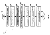
FIG. 9b is a flowchart of exemplary steps for load balancing in accordance with
an embodiment of the invention.
DETAILED DESCRIPTION OF THE INVENTION
Aspects of the invention may provide a system and method for load balancing in
a hybrid wired/wireless local area network. A method for load balancing in a hybrid
wired/wireless local area network may include the step of receiving a polling message
from an access device by at least one of a plurality of access points. In response to the
polling message, a load on one or more of the access points may be determined and
the determined load of one or more of the access points may be received by the access
device. One or more of the access points located within an operating range of the
access device may interpret the polling message. An access point having a least load
may be selected by an access device to provide service.
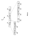
FIG. 1b is a block diagram 120 illustrating a general PLCP frame as defined by
802.11. Referring to FIG. 1 b, there is shown preamble 122, PLCP header 124, MAC
data 126, and CRC 128. Preamble 122 may include synchronization (SYNC) data 122a
and synchronization delimiter 122b. The PLCP header 124 may include, for example
PLCP signal field (PSF) 124a, service data 124b, length 124c and other fields. The
preamble 122 may be dependent on the PHY. The SYNC data 122a may include a
unique bit stream that may be adapted to signal timing parameters such as the start of a
frame. The SYNC data 122a is used for bit synchronization and demodulation. The
SYNC delimiter 122b provides frame timing information and may be adapted to delimit
the end of synchronization information. The PLCP header 124 may be adapted to
contain information used for decoding the frame. For example, the PSF 124a may be
adapted to include communication data rate information. The service data 124b is
generally reserved, but may be utilized to provide application specific functionality. The
length 124c may be adapted to indicate the length of the MAC data 126. In this regard,
the length 124c may be expressed in terms of the time required to transmit the MAC
data 126.
FIG. 1 c is a block diagram 130 illustrating a PLCP frame utilized by frequency
hopping spread spectrum as defined by 802.11. Referring to FIG. 1c, there is shown a
SYNC data 132, PLCP header 134 and PSDU 136. The PLCP header 134 may
include, for example, PSDU length word (PLW) 134a, PLCP signaling field (PSF) 134b,
header error check field or CRC 134c and other fields. The PLW 134a may specify the
number of octets contained in the PSDU 136. The PSF 134 be may be 4-bits in length
and may be used to denote the communication data rate.
FIG. 1d is a block diagram 140 illustrating a PLCP frame for direct sequence
spread spectrum and high rate direct sequence spread spectrum (HR-DSS) as defined
by 802.11. Referring to FIG. 1d, there is shown preamble 142, PLCP header 144 and
MPDU 146. Preamble 142 may include synchronization (SYNC) data 142a and
synchronization delimiter 142b. The PLCP header 144 may include PLCP signal field
(PSF) 144a, service data 144b, length 144c, and CRC field 144d. The SYNC data 142a
may be 128 bits as compared to 8 bits for SYNC data 132a for frequency hopping
spread spectrum. The CRC 144d is 16 bits, which is similar to CRC 134c for frequency
hopping spread spectrum.
FIG. 1e is a block diagram 150 illustrating a PLCP frame for orthogonal
frequency division multiplexing as defined by 802.11. Referring to FIG. 1 e, there is
shown preamble 152, PLCP header 154 and PSDU 156, tail 158 and pad 160.
Preamble 152 may include synchronization (SYNC) data 152a and synchronization
delimiter 152b. The PLCP header 154 may include length 154a, PLCP signal field
(PSF) 154b, reserved field 154c, parity 154d, tail 154e and service 154f. The length
154a is a 12-bit field that may be adapted to indicate the length of the frame. The PSF
154b is a 4-bit field that may indicate a modulation scheme utilized and its associated
coding rate of the PSDU. For example, the specification utilizes binary 1011 to
represent 6 Mbps, 1111 to represent 9 Mbps, 1010 to represent 12 Mbps, 1110 to
represent 18 Mbps, 1001 to represent 24 Mbps, 1011 to represent 36 Mbps, 1000 to
represent 48 Mbps and finally, 1100 to represent the maximum standardized rate if 54
Mbps. The reserved field 154c is a 1 bit field that is reserved for future use and may be
adapted for application specific use. The parity field 154d may indicate odd or even
parity. The tail field 154e is a 6-bit field. The service field 154f is a 16-bit field that may
be adapted to indicate the type of service.
In a typical wireless local area network, especially as access devices become
mobile throughout the network, channel capacity may be rapidly time varying. For
example, when the distance from an access device to an access point increases or
decreases due to mobility, the channel capacity and ultimately the channel throughput
may change due to continuous association and dis-association of access devices with
access points. In accordance with an embodiment of the invention, a switch is provided
to facilitate network management between one or more of a plurality of access devices
and/or access points, and/or other switches. The switch may utilize a messaging
protocol, which may be adapted to facilitate tasks such as load balancing quality of
service (QoS) control and management, switch filter transfer, bandwidth management,
and session control and management.
Referring to the task of load balancing, in a hybrid wired/wireless in which
network capacity may be rapidly changing over time due to the mobility of access
devices, some access points may be overwhelmed with traffic while other access points
may be under utilized. Accordingly, an aspect of the invention provides a method and
system that may be adapted to optimally balance a load among that access points in a
hybrid wired/wireless LAN. The task of load balancing may be a part of a network
management activity which may involve performing one or more activities including, but
not limited to, QoS management, bandwidth management including tracking bandwidth
usage and allocating and de-allocating bandwidth to meet user and/or client demands.
The management of these activities may be directly or indirectly related to providing
mobility and operability throughout a wired or wireless LAN, or a hybrid combination
thereof.
FIG. 2 is a block diagram of an exemplary system for network management in a
wireless local area network in accordance with an embodiment of the invention.
Referring to FIG. 2, there is illustrated a first networking domain 214 and a second
networking domain 234. The first networking domain 214 may include a switch 202,
and access points 204, 206, 208, 210, 212. Each of access points 204, 206, 208, 210,
212 may be coupled to the switch 202. The second networking domain 234 may
include a switch 222, and access points 224, 226, 228, 230, 232. Each of access points
224, 226, 208, 230, 232 may be coupled to the switch 222. Switch 222 may be coupled
to switch 202 through any one or more of a wired and a wireless medium. Although not
shown, at least some of the access points in any one of the networking domains 214,
234 may be coupled to each other. Notwithstanding, a plurality of actual and/or virtual
channels may be provided to facilitate communication with the access points and
switches. Although the networking domains 214 and 234 are illustrated as separate
networking entities, the invention is not so limited. Accordingly, the networking domain
214, 234 may be part of a single networking entity, but may represent separate security
domains within the single networking entity.
In operation, any one or more of the switches 202, 222 may be adapted to send
network management related information and parameters to any one or more of the
access points in any one or more of the networking domains 214, 234. In one
embodiment of the invention, for example, switch 202 may be adapted to communicate
load balancing information to access point 206 and vice versa. Similarly, switch 202
may be adapted to send network management related information to any one or more of
access points 204, 208, 210, 214 and vice versa. Similarly, switch 222 may be adapted
to communicate load balancing related information to any one or more of access points
224, 226, 228, 230, 232 and vice versa. The load balancing information may be used
by an access point to efficiently allocate, distribute and/or de-allocate system resources
for associating and/or dissociating access devices.
In another aspect of the invention, the switches 202, 222 may be adapted to
provide, for example, load balancing activities to the access points using for example a
messaging protocol. Accordingly, some activities such as load balancing, bandwidth
policing, bandwidth management, roaming and handover may be handled by
coordinating one or more switches and one or more access points utilizing, for example,
a messaging protocol. Notwithstanding, a switch for example, switch 222, may be
configured to establish rules that may be adapted by the access points 224, 226, 228,
230, 232 in carrying out these activities. The rules may be propagated from the
switches 222, 202 to the access points 204, 208, 210, 214, 224, 226, 228, 230, 232
using, for example, the messaging protocol. Prioritization and processing, for example,
may be based on acceptable levels of latency and bandwidth availability. For example,
an IP telephone call may be assigned highest queuing and processing priority in order
to minimize latency. Policing, for example, may include performing activities which may
limit and control the usage of available bandwidth by a particular access device or a
type of access device. These and other tasks may be controlled by the switch using the
messaging protocol. Although activities such as policing and QoS management and
bandwidth management may be conducted independently of the load balancing, in
accordance with an aspect of the invention, information may be exchange between
these various activities to ensure optimal load balancing.
In operation, any one or more of the access points in any one or more of the
networking domains may be adapted to determine various load related information and
parameters which may be communicated to one or more of the switches 202, 222. In
an embodiment of the invention, for example, access point 206 may be adapted to
acquire various load related information and communicate the acquired information
back to the switch 202. Similarly, any one or more of access points 204, 208, 210, 214
may acquire various load related information and parameters and communicate the
acquired information to switch 202. In another aspect of the invention, any one or more
of access points 224, 226, 228, 230, 232 may acquire various load related information
and parameters and communicate the acquired information to the switch 222.
In another embodiment of the invention, any one or more of access points 224,
226, 228, 230, 232 may acquire various load related information and parameters and
communicate the acquired information to the switch 202 through switch 222. This may
be particularly useful in, for example, a roaming scenario or handoff scenario. In both
the roaming and handoff scenarios where a particular access device is roaming or being
handed off from networking domain 234 to networking domain 214, it may be
advantageous to acquire bandwidth related information pertaining to networking domain
214 before permitting an access device to acquire service from networking domain 214.
In this case, switch 222 may initiate a query requesting bandwidth related information
from switch 202. Consequently, switch 214 may request bandwidth and/or load related
information from any one or more of access points 204, 206, 208, 210, 212. Once
switch 202 receives the bandwidth related information from these access points, it may
communicate the information to the switch 222. Accordingly, the switch 222 may
determine whether to handoff or permit roaming depending on the load and/or
bandwidth related information received from the switch 202.
Based on, for example, QoS related information received from one or more
access devices or switches, a switch may be adapted to force an access device to
roam. For example, in a case where the switch determines that there may be
insufficient bandwidth or channel capacity to provide a minimal acceptable QoS, then
the switch may be adapted to dynamically force existing and/or new incoming access
devices to roam. In one aspect of the invention, a list of devices that have been forced
to roam may be maintained. Accordingly, if a switch determines that there is sufficient
channel capacity available to provide a minimal acceptable QoS, then the switch may
be adapted to signal or notify devices on the list to reattempt establishment of service
and permit access to the service provided by the network. In this regard, any one or
more of the switches 202, 222 may be adapted to determine the total available
bandwidth or a load for any one or more of a plurality of access points and/or switches.
Accordingly, the switches 202 and/or 222 may provide channel/frequency management
and quality of service QoS management in order to optimally distribute load and
optimize bandwidth utilization for the access devices.
In another embodiment of the invention, based on various load related
information, an access prioritization scheme may be adapted and enforced by, for
example, any one or more of the switches 202, 222. The prioritization scheme may
include, establishing a priority for all network traffic, honoring prioritized traffic from all
clients, and/or honoring prioritized traffic from some select clients such as trusted
clients. In another aspect of the invention, the switches 202, 222 may be adapted to
provide certain load management activities to the access points. Accordingly, some
activities such as bandwidth policing, bandwidth management, packet prioritization and
processing, and service type queuing may be handled by an access point.
Notwithstanding, a switch may be adapted to establish rules that may be utilized
by the access points in carrying out these activities in order to maintain at least minimal
acceptable level of service. Prioritization and processing, for example, may be based
on, for example, acceptable levels of latency and bandwidth availability. For example,
an IP telephone call may be assigned highest queuing and processing priority in order
to minimize latency. Policing, for example, may include tasks which limit and control the
usage of available bandwidth by a particular access device or a type of access device.
Accordingly, bandwidth may be fairly distributed amongst access devices to ensure at
least a minimal acceptable level of service.
In accordance with an aspect of the invention, the switch may utilize the
messaging protocol (MP) to provide enhanced communication services to one or more
of a plurality of access devices or mobile stations in, for example, an enterprise
Wireless LAN (WLAN). The enhanced communication, in addition to ordinary WLAN
device communication such as authentication, authorization, key exchanges, beacon
broadcast, etc., may provide additional network management features not currently
provided by a WLAN to its clients. These additional features may include, but are not
limited to, quality of service management, bandwidth management, access control, load
balancing and network management. In addition to switches, other enterprise WLAN
devices that may utilize messaging protocol message transactions may include but are
not limited to, wireless access points, enterprise switches and wireless stations. These
devices may be messaging protocol enabled in certain instances, to take advantage of
the new network management features.
In accordance with an aspect of the invention, an exemplary WLAN architecture
may be provided. In the enterprise Wireless LAN environment, the wireless devices
may be located at the edge of the network. The wireless devices may be connected or
coupled to the enterprise network via the one or more access points, which in turn may
be the edge devices of, for example, a wired LAN. The access points may be
connected to the LAN via switches. These switches, which may be called wireless LAN
switches, and in certain instances, may not only perform Layer 2 switching, but may be
adapted to function as a wireless edge managers. They may also provide additional
network management functionalities such as load balancing, bandwidth management,
access control, firewall functions, and traffic privacy and quality of service management.
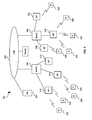
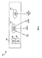
FIG. 3 is a block diagram 300 of an exemplary Enterprise Wireless LAN having
switches serving as the edge managers in accordance with an embodiment of the
invention. Referring to FIG. 3, there is shown, a local area network (LAN) 302,
authentication server 304, switches 306, 308, access points (APs) 310, 312, 314, 316,
318, 320 and access devices 322, 324, 326, 328, 330, 332, 334, 336, 338. It should be
recognized that the invention is not limited to and Enterprise WLAN. The invention may
be applicable to a wired LAN, a wireless LAN and any combination thereof.
Wireless transmission or communication between the access devices or clients,
and the access points may be secure. This may be also be true for the wired
connections between any of the access points 310, 312, 314, 316, 318, 320 and the
switches 306, 308. The switches 306, 308 and access points 310, 312, 314, 316, 318,
320 may be adapted to communicate using, for example, an Ethernet protocol. From
the switch's perspective, the switch may be switching regular layer 2 frames. However,
within the switch, knowledge of a WLAN and its management intelligence may reside
primarily in software. Notwithstanding, the invention is not limited in this regard.
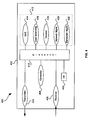
FIG. 4 is a block diagram 400 of an exemplary switch 402 as illustrated in FIG. 2
and FIG. 3 in accordance with an embodiment of the invention. Referring to FIG. 4,
switch 402 may include a processor 410, transmitter 404, receiver 406, generator 408
and controller 412. The controller 412 may include QoS controller 414, bandwidth
controller 422, load balancing controller 416, session controller 418 and network
management controller 420. The transmitter 404, receiver 406, generator 408 and the
components of the controller 412, namely QoS controller 414, load balancing controller
416, session controller 418 and network management controller 420, may be variously
coupled to processor 410.
The components of switch 402 may include suitable circuitry and/or software
capable of implementing the various network management functions, including but not
limited to, load balancing, QoS management, bandwidth management, session
management and control. Notwithstanding, although the components of the switch 402
are individually shown, the invention is not limited in this regard. For example, with
suitable software and/or logic, the generator function 408 may be implemented solely by
the processor 422. Similarly, any one or more of the bandwidth management, QoS
management, load balancing, session management and control, and network
management may be integrated, and with suitable logic and/or software, may be
executed by the processor 410.
In operation, the transmitter 404 may be adapted to send a first messaging
protocol message between a first switch and a first access point. The receiver 406 may
be adapted to receive a second messaging protocol message from the first access point
and the first switch. In response to the transmittal of the first messaging protocol
message, a second messaging protocol message may be received. The controller 412
may be adapted to allocate system resources for one or more devices using any one or
more of the first second and/or third messaging protocol messages. These devices
may include but are not limited to the first switch, a second switch, the first access point,
the second access point, and one or more access devices. The system resources may
be allocated to ensure that at least minimal acceptable level of service is maintained.
The generator 408 may be adapted to generate the first messaging protocol
message by the first switch. The receiver 406 may be adapted to receive the second
messaging protocol message from a second switch. The processor 410 may be
adapted to control the transmitter 404, the receiver 406, the controller 412 and the
generator 408. The processor 410 may utilize one or more messaging protocol
messages to control transmitter 404, receiver 406, generator 408, bandwidth controller
422, QoS controller 414, load balancing controller 416, session controller 418 and
network management controller 420.
In accordance with an aspect of the invention, the switch may be adapted to
facilitate network management, including activities such as, QoS management and
bandwidth management, by utilizing a messaging protocol. The messaging protocol
may utilize one or more protocols associated with a device communication protocol
(DCP) umbrella (DCPU). The messaging protocol utilized by the switch may be
adapted to run over the transmission control protocol (TCP) or user datagram protocol
(UDP) using for example, a well-known port number specified under the framework of
the device communication protocol. Under the DCP umbrella, there may be several
sub-protocols defined for the purpose of facilitating interoperability with other products.
Some of these products may include but are not limited to, cable modems and cable
modem termination systems (CMTS) equipment. The messaging protocol utilized by
the switch may be adapted to include the necessary protocols under DCP to facilitate
communication for wired and/or WLAN devices.
In accordance with an aspect of the invention, the switch may utilize the
messaging protocol to facilitate various network management activities between various
wireless networking devices and/or clients. In an embodiment of the invention, one or
more of WLAN switches 306, 308 may be adapted to utilize the messaging protocol to
facilitate communication with one or more of the access points 310, 312, 314, 316, 318,
320 of FIG. 3. Information exchanged between these two devices may include, but is
not limited to, control, configuration and status information of the devices and also client
session information. At least some of this information may be used for load balancing.
The control information may include, for example, signaling information that may be
communicated in-band or out-of-band.
The switch may utilize the messaging protocol, which may include a plurality of
message types. In accordance with an aspect of the invention, the switch may utilize a
messaging protocol that may include, for example, six (6) categories of messages or
message types. Notwithstanding, the invention is not so limited. These messages and
their usage may be illustrated as follows:
In each of the message types above, the message may include, for example four
(4) message subtypes ― .request, .data, .alert, and .ack. A message type/subtype pair
of .request and .data may represent the request of data and a corresponding response
of data itself. The subtype pair of .alert and .ack may represent the voluntary
transmission of data and its acknowledgement. Additionally, there may be two
conventions utilized in a message exchange sequence. Accordingly, if a message
exchange sequence starts with a request (.req), it may be followed by a reactive
transmission of data (.data). Similarly, if a message exchange sequence starts with a
proactive transmission of data (.alert), it is followed by an acknowledgement (.ack). In
accordance with an aspect of the invention, one or more message types and/or subtype
may be used to facilitate bandwidth management.
United States Patent Application Serial No. 10/607,094 entitled "Communication
System and Method in a Hybrid Wired/Wireless Local Area Network" filed on June 26,
2003, discloses a messaging protocol that may be utilized by the switch in accordance
with an embodiment of the invention, and is incorporated herein by reference in its
entirety. Exemplary valid fields and subfields for various messaging protocol messages
that may be utilized by the switch in accordance with an aspect of the invention are
disclosed therein. Additionally, United States Patent Application Serial No.
(Attorney Docket No. 14178US02) entitled "Method and System for Providing an
Intelligent Switch in a Hybrid Wired/Wireless Local Area Network" filed on September 9,
2003, discloses a messaging protocol that may be utilized by the switch in accordance
with an embodiment of the invention, and is incorporated herein by reference in its
entirety. The switch disclosed therein may be adapted to utilize the messaging protocol
to provide network management in accordance with an embodiment of the invention.
In another embodiment of the invention, the switch may include a network
management controller that may be configured for network management and may
provide valuable information that may be utilized for load balancing. In this regard, the
switch may be adapted to utilize, for example, the messaging protocol to transfer
networking monitoring and/or status messages such as SNMP and RMON statistics
from an old attachment or connection point to a new connection point. In this regard,
the switch may be configured to use the messaging protocol to enable location-specific
management of at least certain clients and/or network devices. In this regard, the
switch may send client association information to a central management entity which
may be aware of the location of the various access points and/or switches in the
network. This information may be disseminated to, for example a QoS controller, a
bandwidth controller and/or a load balancing controller. Accordingly, a decision may
subsequently be made to determine whether to allow or disallow access from certain
locations in order to maximize bandwidth usage, balance a load within the network
and/or provide a specified QoS.
For example, information pertaining to at least some detected clients may be
transferred to the switch. Accordingly, the load balancing manager and/or controller
located in the switch may use this information to achieve efficient load balancing. In this
regard, the load balancing controller may include suitable circuitry and/or software that
may be adapted to receive and assess various client information and effectuate an
efficient load balancing. Parameters such as signal strength, access level and device
type, may be indicative of the information that may be used to effectuate optimal load
balancing. Client association/dissociation information may be communicated between
the load balancing manager and one or more access points and/or switches in order to
ensure that an acceptable level of service may be received by accessing clients. Once
the load-balancing manager determines an optimal load configuration, new client and/or
access point association information may be passed to the various access points in the
network using messaging protocol messages.
In another embodiment of the invention, the switch may include a QoS controller
that may be configured to utilize the messaging protocol to transfer QoS parameters
from an original switch port to a new switch port, in order to facilitate roaming. One or
more switches in the network may be adapted to facilitate roaming between various
access points located in the same network or between different networks. This may
affect the QoS handling of, for example, downstream traffic destined for the roaming
client or access device. In this regard, a switch may be adapted to utilize one or more
messaging protocol messages to automatically transfer various pertinent centralized
management may eliminate a need for a distributed management interface, thereby
providing a more robust communication system.
In another embodiment of the invention, to facilitate roaming, a switch may be
adapted to utilize the messaging protocol to transfer QoS parameters from an old
access point to a new access point. This may affect upstream traffic from the client to
an access point. In this regard, the switch may utilize one or more messaging protocol
messages to transfer Q0S and load parameters from the old access point to the new
access point. Since this handling of QoS and load parameters may be similar to the
handling of client traffic, the messaging protocol may be used to provide seamless
roaming, which may provide a greater level of acceptable service.
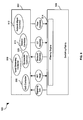
FIG. 5 is a block diagram 500 of an exemplary switching system for network
management in a wireless local area network. Referring to FIG. 5, there is shown a
CPU block 502 and a switching fabric block 804. The CPU block 502 may include a
quality of service (QoS) controller block 506, a bandwidth management controller block
520, a load balancing controller block 508, a session controller block 510 and a network
management control block 512. The switching fabric block 504 may include a filtering
engine block 514. The CPU block 502 may be adapted to interface with the switching
fabric block 504. One or more of the QoS controller block 506, load balancing controller
block 508, session controller block 510 and network management control block 512
may interface directly with the filtering engine block 514.
In operation, selected signaling packets may be communicated from the
switching fabric block 504 to one or more of the QoS controller block 506, bandwidth
management controller block 520, load balancing controller block 508, session
controller block 510 and network management control block 512. Messaging protocol
messages may be used to facilitate communication between the switching fabric block
504 and one or more of the bandwidth management controller block 520, QoS controller
block 506, load balancing controller block 508, session controller block 510 and network
management control block 512. The selected signaling packets may include, but are
not limited to, VolP packets, and streaming media packets including voice, video and
data. The filtering engine block 514 may be adapted to filter information received from
one or more of the QoS controller block 506, bandwidth management controller block
520, load balancing controller block 508, session controller block 510 and a network
management control block 512. In this regard, the filtering engine block 514 may be
adapted to filter messaging protocol messages used to control switching functions,
network traffic statistics messages, layer two (2) address update messages, and filter
update messages. The filter update messages may include, but is not limited to, QoS
messages, bandwidth management messages, access control messages and load
balancing messages.
In accordance with an embodiment of the invention, a session control process
may be adapted to manage and control at least one client database and session
information for some or all active clients. In an embodiment of the invention, the
switching system for network management may be adapted to provide session
management information that may be utilized for bandwidth management. The session
control process may be configured to enforce access control based on, for example, a
client session, a subnet, a network management application, and switch ports. Access
control may be used to facilitate, for example, QoS management, bandwidth
management and load balancing in at least a portion of the network. The session
control process may also control and manage switching intelligence and to determine
bandwidth availability in order to facilitate activities such as roaming.
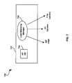
FIG. 6 is a block diagram 600 of an exemplary session control process with
respect to FIG. 5 that may be utilized by the switching system for network management
in accordance with an embodiment of the invention. Referring to FIG. 6, there is shown
a session control process 602 having a client database 604, an access control list (ACL)
database 606, a session control manager 608 and a VolP enabler 610. One or more
interfaces may be adapted to provide communication between session manager 608
and the client database 604 and the ACL database 606. The session manager 608
may include at least one interface that may be adapted to facilitate communication with
the VolP enabler 610.
The ACL may be adapted for filtering traffic based on identifiable attributed within
a frame such as an Ethernet frame. Data may be filtered based on its source,
destination or MAC address, the protocol utilized and various protocol-specific options
such as FTP, TFTP, HTTP and SNMP.
In operation, the session control manager 608 may be adapted to process, for
example, messaging protocol messages, layer two (2) updates, and filter updates. The
session control manager 608 may be adapted to receive information from one or more
of client database 604 and ACL database 606. The VolP enabler 610 may be adapted
to process VolP signaling packets. VolP enabler 610 may also be adapted to decode
various standards-based VolP signaling packets and prioritize filter setup. Information
from the session control manager 608 may be communicated to the bandwidth
management controller 520, the QoS controller 506, the load balancing controller 508,
and the network management controller 512, which are illustrated in FIG. 5.
In an embodiment of the invention, the switching system 602 may include a load
balancing process that may be adapted to obtain access point load from, for example, a
QoS management process and a bandwidth management process. The network
management process may include but is not limited to SNMP, RMON, RMON2, and
MIB. The load balancing process may be adapted to keep an access point database
on, for example, a plurality or bank of access points. The load balancing process may
include necessary intelligence for making load distribution decisions.
The access point database may be accessible by one or more of the QoS
controller 506, the bandwidth management controller 520, the load balancing controller
508, and the network management controller 512 which are illustrated in FIG. 5. In
addition, the bandwidth management controller 520 may be adapted to request
information from the session control manager 608 and/or the load balancing process in
order to facilitate activities such as bandwidth management. Load balancing may
optimize aggregate bandwidth and may provide intelligent client associations with an
access device.
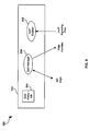
FIG. 7 is a block diagram 700 of an exemplary load balancing process with
respect to FIG. 6 that may be utilized by the switching system for network management
in accordance with an embodiment of the invention. Referring to FIG. 7, there is shown
a load balancing process 702 having an access point database 702 and a load
balancing manager 706. At least one interface may be adapted to provide
communication between access point database 704 and the load balancing manager
706. The load balancing manager 706 may be adapted to include at least one interface
that may facilitate communication with a network management process.
In operation, the load balancing manager 706 may be adapted to process
messaging protocol messages, layer two (2) updates, and filter updates. The load
balancing manager 706 may receive network statistics from a one or more network
management processes. Information from the access point database 704 may be
utilized by the load balancing manager 706 for making load balancing decisions.
In an embodiment of the invention, the switching system for network
management may include load balancing may be adapted to control and manage
activities such as, traffic policing, metering filters, and protocol configurations. In this
regard, the QoS enabling process may be adapted to manage, for example, 8012.11 e
based configurations that may be sent to the access point. A VoIP enabler may be
adapted to decode various standard-based VolP signaling packets and prioritize filter
setup.
FIG. 8 is a block diagram 800 of an exemplary QoS enabling process with
respect to FIG. 8 that may be utilized by an the switching system for network
management in accordance with an embodiment of the invention. Referring to FIG. 8,
there is shown QoS enabling process 802 having QoS policy database 804, a QoS
manager 806 and a VolP enabler 808. At least one interface may be adapted to
provide communication between QoS policy database 804 and the QoS manager 806.
The QoS manager 806 may be adapted to include at least one interface that may
facilitate communication with, for example, the VoIP enabler 808.
In operation, the QoS manager 806 may be adapted to process, for example,
messaging protocol messages, and filter updates. The QoS manager 806 may send
and receive VoIP signaling information to and from VolP enabler 808 806 for making
QoS related decisions. In certain instances, information related to the QoS
management may be utilized for bandwidth management. Accordingly, with reference
to FIG. 4, the bandwidth management controller 412 may be adapted to receive
pertinent QoS related information from the QoS controller 414'.
In one aspect of the invention, the QoS controller 414, the load balancing
controller 416, the session controller 418, the network management controller 420
and/or the bandwidth management controller 412 may be adapted to transfer and/or
store information in a database, for example, database 424. In this regard, the QoS
controller may be adapted to store at least some of its related QoS related information
in database 424. Accordingly, whenever a need arises, the load balancing controller
416 may access database 424 and retrieve any QoS related information that may be
pertinent to bandwidth management.
In another aspect of the invention, in certain instances, the load balancing
controller 416 may be adapted to request related load information from bandwidth
management controller 422 and/or QoS from the QoS controller 414. To facilitate load
balancing, real-time information not necessarily located in the database 424 may be
requested from the QoS controller 414 or bandwidth controller 422 whenever a need
arises. Additionally, through this mechanism, the load balancing controller 416 may be
adapted to also request an receive related information from the session controller 418,
the network management controller 420 and/or the database 424. The load balancing
process may be executed in an adaptive manner and may occur in real-time.
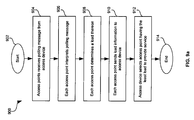
FIG. 9a is a flowchart 900 of exemplary steps for load balancing in accordance
with an embodiment of the invention. Referring to FIG. 9a, subsequent to start step
902, in step 904, access points may receive polling message from access device. In
step 906, each access point may interpret the polling message. In step 908, each
access point may determine a load thereon. In step 910, each access point may send
load information to the polling access device. In step 912, the polling access device
may select the access point having the least load to provide service. Subsequent to
step 912, the exemplary steps may end with step 914.
FIG. 9b is a flowchart 920 of exemplary steps for load balancing in accordance
with an embodiment of the invention. Referring to FIG. 9b, subsequent to start step
922, in step 924, an access device may broadcast a polling message. In step 926,
each access point within operating range of the polling access device may receive the
polling message. In step 928, each access point may interpret the polling message. In
step 930, each access point may send load information to a switch. In step 932, the
switch may determine the aggregate load on the access points and determine and
optimal load balancing. In step 934, the switch may sent load information to the access
points which may redistribute their load. In step 936, the access device may select an
access point having the least load to provide service. Subsequent to step 936, the
exemplary steps may end with step 938.
Notwithstanding, the exemplary steps illustrated in FIG. 9a and FIG. 9b, it should
be recognized that other steps may be added, substituted or made optional without
departing from the scope of the invention. Referring to FIG. 9a, for example, step 904
may be an optional step. In this regard, an access point and/or a switch may be
adapted to send QoS information, for example in a dynamic manner, using a messaging
protocol message to the switch.
In accordance with another embodiment of the invention, dependent on the
modulation scheme utilized, one or more of the PLCP frames illustrated in FIG. 1 b, FIG.
1c, FIG. 1d and FIG. 1e may be adapted to contain information which may be utilized
for providing communication in accordance with various embodiments of the invention.
Additionally, the PLCP frames may be adapted to convey information for any one or
more of the 801.11 a, 802.11 b and 802.11 g modes of operation utilized by access points
and/or access devices in accordance the embodiments of the invention.
Accordingly, the present invention may be realized in hardware, software, or a
combination of hardware and software. The present invention may be realized in a
centralized fashion in one computer system, or in a distributed fashion where different
elements are spread across several interconnected computer systems. Any kind of
computer system or other apparatus adapted for carrying out the methods described
herein is suited. A typical combination of hardware and software may be a general-purpose
computer system with a computer program that, when being loaded and
executed, controls the computer system such that it carries out the methods described
herein.
The present invention also may be embedded in a computer program product,
which comprises all the features enabling the implementation of the methods described
herein, and which when loaded in a computer system is able to carry out these
methods. Computer program in the present context means any expression, in any
language, code or notation, of a set of instructions intended to cause a system having
an information processing capability to perform a particular function either directly or
after either or both of the following: a) conversion to another language, code or
notation; b) reproduction in a different material form.
Notwithstanding, the invention and its inventive arrangements disclosed herein
may be embodied in other forms without departing from the spirit or essential attributes
thereof. Accordingly, reference should be made to the following claims, rather than to
the foregoing specification, as indicating the scope of the invention. In this regard, the
description above is intended by way of example only and is not intended to limit the
present invention in any way, except as set forth in the following claims.
While the present invention has been described with reference to certain
embodiments, it will be understood by those skilled in the art that various changes may
be made and equivalents may be substituted without departing from the scope of the
present invention. In addition, many modifications may be made to adapt a particular
situation or material to the teachings of the present invention without departing from its
scope. Therefore, it is intended that the present invention not be limited to the particular
embodiment disclosed, but that the present invention will include all embodiments falling
within the scope of the appended claims.