EP1515209A1 - Regeleinrichtung für einen mehrachsigen Roboter - Google Patents
Regeleinrichtung für einen mehrachsigen Roboter Download PDFInfo
- Publication number
- EP1515209A1 EP1515209A1 EP04021712A EP04021712A EP1515209A1 EP 1515209 A1 EP1515209 A1 EP 1515209A1 EP 04021712 A EP04021712 A EP 04021712A EP 04021712 A EP04021712 A EP 04021712A EP 1515209 A1 EP1515209 A1 EP 1515209A1
- Authority
- EP
- European Patent Office
- Prior art keywords
- axis
- controller
- control device
- robot
- controllers
- Prior art date
- Legal status (The legal status is an assumption and is not a legal conclusion. Google has not performed a legal analysis and makes no representation as to the accuracy of the status listed.)
- Granted
Links
Images

Classifications
-
- G—PHYSICS
- G05—CONTROLLING; REGULATING
- G05B—CONTROL OR REGULATING SYSTEMS IN GENERAL; FUNCTIONAL ELEMENTS OF SUCH SYSTEMS; MONITORING OR TESTING ARRANGEMENTS FOR SUCH SYSTEMS OR ELEMENTS
- G05B19/00—Program-control systems
- G05B19/02—Program-control systems electric
- G05B19/18—Numerical control [NC], i.e. automatically operating machines, in particular machine tools, e.g. in a manufacturing environment, so as to execute positioning, movement or co-ordinated operations by means of program data in numerical form
- G05B19/404—Numerical control [NC], i.e. automatically operating machines, in particular machine tools, e.g. in a manufacturing environment, so as to execute positioning, movement or co-ordinated operations by means of program data in numerical form characterised by control arrangements for compensation, e.g. for backlash, overshoot, tool offset, tool wear, temperature, machine construction errors, load, inertia
-
- G—PHYSICS
- G05—CONTROLLING; REGULATING
- G05B—CONTROL OR REGULATING SYSTEMS IN GENERAL; FUNCTIONAL ELEMENTS OF SUCH SYSTEMS; MONITORING OR TESTING ARRANGEMENTS FOR SUCH SYSTEMS OR ELEMENTS
- G05B2219/00—Program-control systems
- G05B2219/30—Nc systems
- G05B2219/39—Robotics, robotics to robotics hand
- G05B2219/39201—Control of joint stiffness
-
- G—PHYSICS
- G05—CONTROLLING; REGULATING
- G05B—CONTROL OR REGULATING SYSTEMS IN GENERAL; FUNCTIONAL ELEMENTS OF SUCH SYSTEMS; MONITORING OR TESTING ARRANGEMENTS FOR SUCH SYSTEMS OR ELEMENTS
- G05B2219/00—Program-control systems
- G05B2219/30—Nc systems
- G05B2219/42—Servomotor, servo controller kind till VSS
- G05B2219/42075—Two position loops
-
- G—PHYSICS
- G05—CONTROLLING; REGULATING
- G05B—CONTROL OR REGULATING SYSTEMS IN GENERAL; FUNCTIONAL ELEMENTS OF SUCH SYSTEMS; MONITORING OR TESTING ARRANGEMENTS FOR SUCH SYSTEMS OR ELEMENTS
- G05B2219/00—Program-control systems
- G05B2219/30—Nc systems
- G05B2219/45—Nc applications
- G05B2219/45065—Sealing, painting robot
Definitions
- the invention relates to a control device for a multi-axis Robot, in particular for a painting robot Painting plant, according to the preamble of claim 1.
- the desired spatial coordinates of a so-called TCP (English: TCP - T ool C enter P oint) are conventionally specified and converted into the corresponding axis coordinates for the individual axes of the painting robot in accordance with a robot-specific inverse kinematics.
- the drive of the individual axes of the painting robot takes place here by electric motors, which are controlled by one controller for each axis.
- a disadvantage of the known control device described above for a robot is the fact that the Positioning accuracy, especially for fast movements of the robot is unsatisfactory.
- the invention is therefore based on the object at a Control device for a multi-axis robot positioning accuracy to increase.
- the invention is based on the technical knowledge that the Positioning accuracy of a multi-axis robot through the elasticity of the individual axes is impaired. For example, if an axis of the robot due to a Intermediate transmission is very elastic, so speaks this axis only delayed on a setpoint change, whereas Stiffer axes of the robot of the setpoint change follow faster. The delayed response of highly elastic However, axes are not taken into account in the previous regulation and therefore leads to positioning errors of the robot.
- the invention therefore comprises the general technical teaching, in a control device with several controllers for drive control one axis each of the multi-axis robot the individual controller axes to each other across axes couple, so different elasticities of the individual Axes considered and compensated in the other axes can be.
- the cross-axis coupling acts between the individual controllers here by the controller of a relative yielding axis on the regulator of a relatively stiff axis.
- the controller of a relative yielding axis on the regulator of a relatively stiff axis is advantageous because the elasticity-related positioning errors essentially by the yielding axes caused and therefore from the stiffer axes should be compensated.
- the cross-axis coupling between the individual axis-based robots of the multi-axis robot Control deviation of at least one of the controllers. This means, that detects the control deviation in one axis of the robot and in another axis.
- the use of the control deviation of one of Torque controller for cross-axis coupling makes sense because this regulator size the elasticity of each Axis reflects that under cross-axis Coupling should be compensated.
- controller size not limited to target-actual deviations of the torque, but also with other controller sizes feasible.
- control device is thus the control behavior of the controller of at least one axis not only of the target-actual deviation of the own axis depends, but is preferred due to the cross-axis coupling also influenced by the nominal-actual deviation of another axis.
- the cross-axis coupling between the individual axes through a coupling loop the On the input side, the nominal-actual deviation of a controller size (e.g., torque) on an axle and on the output side controls the controller of another axis.
- a controller size e.g., torque
- the coupling loop is preferably a low-pass filter, an absolute value element, an inverter, an amplifier and / or a saturating member arranged.
- the arrangement of a low-pass filter in the coupling loop is useful to filter out higher-frequency interference, the not caused by the elasticity of the respective axis become.
- a saturator is arranged to the control behavior of the control device to optimize.
- At least one of the regulators is a cascade controller, which has several cascaded control loops, the cross-axis coupling to one or more several of the outer control circuits acts.
- the cascade controller position, speed, torque and Have current control loops that nest together are, with the coupling between the axis-related controllers acts on one or more of the outer control loops.
- the invention is also a Configurability of the coupling between the individual axes intended. For example, you can freely configure Which controller across axes on which other axis-related Regulator works.
- the coupling behavior can also be between the individual axis-related controllers be freely configured, with the coupling behavior can differ for the individual axis-related controller.
- the invention is not limited to those described above Control device according to the invention, but also a robot, in particular a painting robot with a Such painting and a coating system with a robot equipped according to the invention.
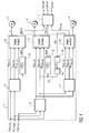
- the simplified block diagram in Figure 1 shows an inventive Control device 1 for electrical control of electric motors 2, 3, 4 of a multi-axis robot, the
- a painting robot can be used to an application device, such as a rotary atomizer, in a painting booth of a coating plant position.
- an application device such as a rotary atomizer
- the invention is not on the drive triaxial robot is limited, but is preferably used to control multi-axis robots.
- control device 1 receives space coordinates x TCP, SETPOINT , y TCP, DESIRED and z TCP, SOLL of a so-called TCP (TCP - T ool C enter P oint), which determine the desired trajectory of an application device mounted on the TCP.
- SOLL From the spatial coordinates x TCP, SOLL , y TCP, SOLL and z TCP, SOLL several computing units 5, 6, 7 calculate according to a predetermined inverse kinematics the corresponding setpoints s SOLL , v SOLL , M SOLL for the position, the speed and the torque in each axis of the robot.
- controllers 8-10 are shown in detail in Figures 2 and 3 and will be described in more detail.
- the regulators 8-10 regulate the current I 1 , I 2 or I 3 for controlling the electric motors 2-4 in the individual axes.
- Figure 1 shows in the context of the illustrated control engineering Equivalent circuit diagram another arithmetic unit 11, which are calculated internally by the regulators 8-10 Actual values for the position of the respective axis are the associated ones Calculate actual values for the position of the TCP.
- the arithmetic unit 11 is not part of the invention Control device, but serves here only for clarity the principle of the invention.
- the individual axis-related controller 8-10 do not work independently but with each other are coupled. So is the regulator 10 for the most elastic Axis of the robot the deviation ⁇ M between Actual value and target value of the torque M tapped and in Frame of a feedback loop 12 to the input of Regulator 8, 9 of the stiffer axes of the robot returned.
- the feedback loop 12 in this case allows for compensation the elasticity delayed response of the the controller 10 associated axis by the of the controllers 8, 9 driven stiffer axles.
- an absolute value member 13 which is the absolute value of the control deviation ⁇ M is calculated as the sign of the control deviation ⁇ M for the elasticity-related delayed response insignificant is.
- the feedback loop 12 then branches behind the saturator 14 in two separate branches, the individual Regulator 8, 9 are fed, wherein in the two separate Branches of the feedback loop 12 each have a low-pass filter 15, 16 is arranged.
- the two low-pass filters 15, 16 have the task of higher frequency interference signals from the feedback loop 12 filter out.
- the regulator 10 is the most elastic axis of the multi-axis Robot controls.
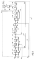
- the controller 10 receives from the arithmetic unit 7, the setpoints S SOLL , V SOLL and M SOLL for position, speed and torque of the third axis.
- the desired value S SOLL for the positions of the third axis is first supplied to a limiter 17, which limits the desired value S SOLL and supplies it to a subtracter 18.
- the subtraction input of the subtracter 18 is connected to a feedback loop 19, which returns the actual position S IST of the third axis, as will be described in detail.
- the subtractor 18 On the output side is the subtractor 18 with a PID controller 20 connected to a limiter 21 is connected downstream.
- the limiter 21 On the output side, the limiter 21 is connected to an adder 22, which adds the output from the limiter 21 setpoint value for the speed of the third axis to the input-side recorded setpoint V SOLL the speed and a subtractor 23 supplies.
- the subtraction input of the subtractor 23 is in turn connected to a feedback loop 24, which returns the actual value of the speed V IST of the third axis, as will also be described in detail.
- the subtractor 23 supplies the control deviation .DELTA.v to a PID controller 25, to which a further limiter 26 is connected downstream.
- a target value then appears M 'SOLL for the torque of the electric motor 4 in the third axis said target value by an adder 27 to the input side captured target value M SOLL added together and then supplied to a subtractor 28 becomes.
- the subtraction input of the subtractor 28 is provided with an in a feedback loop arranged transfer member 29th connected, so that the subtractor 28, the control deviation ⁇ M of the torque control loop outputs.
- a further PID controller 30 and a limiter 31 is arranged so that the value of the current i IST appears at the output of the limiter 31, with which the electric motor 4 of the third axis is controlled.
- a transfer element 32 is arranged behind the limiter 31 and calculates the associated speed value v IST from the current value i actual .
- a further transmission element 33 is provided which calculates the associated position s IST from the velocity v actual .
- the equivalent circuit diagram of regulator 10 shows two transmission elements 34, 35 which, taking into account the elasticity of the third axis, calculate the associated elasticity-corrected values of speed v * IST and position s * IST .
- controller 8, 9 largely agree with the Regulator 10 match, allowing to avoid repetition largely to the above description of the controller 10 and below for corresponding components the same reference numerals are used, which are only for Distinction characterized by an apostrophe.
- a special feature of the regulator 8 is that this via the feedback loop 12 on the input side, a correction variable Input receives an additional subtractor 36 is supplied.
- the subtracter 36 forms the difference between the setpoint value S SOLL received on the input side for the position of the first axis and the input input correction variable Input and uses the difference below as a reference variable.
- the input correction quantity input is fed via an amplifier 37 to a further subtractor 38, which forms the difference between the input value v SOLL for the speed of the first axis and the input value recorded on the input side, wherein the subtracter 38 has a correspondingly corrected reference variable v * SOLL , which is supplied to the adder 22 ', as described above for Figure 2.
Landscapes
- Engineering & Computer Science (AREA)
- Human Computer Interaction (AREA)
- Manufacturing & Machinery (AREA)
- Physics & Mathematics (AREA)
- General Physics & Mathematics (AREA)
- Automation & Control Theory (AREA)
- Manipulator (AREA)
- Numerical Control (AREA)
Abstract
Description
- Figur 1
- eine erfindungsgemäße Regeleinrichtung für einen mehrachsigen Lackierroboter mit jeweils einem Regler für die einzelnen Achsen,
- Figur 2
- ein regelungstechnisches Ersatzschaltbild des Reglers der beiden relativ steifen Achsen 1 und 2 sowie
- Figur 3
- den Regler der relativ elastischen Achse 3 in Form eines regelungstechnischen Ersatzschaltbildes.
Claims (12)
- Regeleinrichtung (1) für einen mehrachsigen Roboter, insbesondere für einen Lackierroboter einer Lackieranlage, mit mehreren Reglern (8-10) zur Antriebsregelung jeweils einer Achse des Roboters, dadurch gekennzeichnet, dass mindestens zwei Regler (8-10) unterschiedlicher Achsen achsenübergreifend miteinander gekoppelt sind.
- Regeleinrichtung (1) nach Anspruch 1, dadurch gekennzeichnet, dass die einzelnen Achsen des Roboters eine unterschiedliche mechanische Steifigkeit aufweisen, wobei die achsenübergreifende Kopplung von dem Regler (10) einer relativ nachgiebigen Achse auf den Regler (8, 9) einer relativ steifen Achse wirkt.
- Regeleinrichtung (1) nach Anspruch 1 oder 2, dadurch gekennzeichnet, dass die achsenübergreifende Kopplung zwischen den Reglern (8-10) eine Regelabweichung (ΔM) eines der Regler (10) betrifft.
- Regeleinrichtung (1) nach Anspruch 3, dadurch gekennzeichnet, dass die achsenübergreifende Kopplung zwischen den Reglern (8-10) die Regelabweichung (ΔM) eines Drehmomentreglers betrifft.
- Regeleinrichtung (1) nach einem der vorhergehenden Ansprüche, dadurch gekennzeichnet, dass zur achsenübergreifenden Kopplung zwischen den Reglern (8-10) mindestens eine Kopplungsschleife (12) vorgesehen ist, wobei in der Kopplungsschleife ein Tiefpassfilter (15, 16), ein Absolutwertglied (13), ein Inverter, ein Verstärker und/oder ein Sättigungsglied (14) angeordnet ist.
- Regeleinrichtung (1) nach einem der vorhergehenden Ansprüche, dadurch gekennzeichnet, dass der Regler (10) einer Achse achsenübergreifend auf die Regler (8, 9) aller anderen Achsen zurückgekoppelt ist.
- Regeleinrichtung (1) nach einem der vorhergehenden Ansprüche, dadurch gekennzeichnet, dass mindestens einer der Regler (8-10) ein Kaskadenregler ist, der mehrere kaskadenförmige Regelkreise aufweist, wobei die achsenübergreifende Kopplung auf einen oder mehrere der äußeren Regelkreise wirkt.
- Regeleinrichtung (1) nach einem der vorhergehenden Ansprüche, dadurch gekennzeichnet, dass konfigurierbar ist, welche Regler (8-10) achsenübergreifend miteinander gekoppelt sind.
- Regeleinrichtung (1) nach einem der vorhergehenden Ansprüche, dadurch gekennzeichnet, dass das Kopplungsverhalten zwischen den einzelnen Reglern (8-10) konfigurierbar ist.
- Regeleinrichtung (1) nach einem der vorhergehenden Ansprüche, dadurch gekennzeichnet, dass die achsenübergreifende Kopplung zwischen den Reglern (8-10) eine antriebsseitig erfasste Reglergröße (ΔM) betrifft.
- Roboter, insbesondere Lackierroboter, mit einer Regeleinrichtung (1) nach einem der vorhergehenden Ansprüche.
- Beschichtungsanlage mit einem Roboter nach Anspruch 11.
Applications Claiming Priority (2)
| Application Number | Priority Date | Filing Date | Title |
|---|---|---|---|
| DE10342471A DE10342471B4 (de) | 2003-09-15 | 2003-09-15 | Regeleinrichtung für einen mehrachsigen Roboter |
| DE10342471 | 2003-09-15 |
Publications (2)
| Publication Number | Publication Date |
|---|---|
| EP1515209A1 true EP1515209A1 (de) | 2005-03-16 |
| EP1515209B1 EP1515209B1 (de) | 2006-11-02 |
Family
ID=34129808
Family Applications (1)
| Application Number | Title | Priority Date | Filing Date |
|---|---|---|---|
| EP04021712A Expired - Lifetime EP1515209B1 (de) | 2003-09-15 | 2004-09-13 | Regeleinrichtung für einen mehrachsigen Roboter |
Country Status (4)
| Country | Link |
|---|---|
| EP (1) | EP1515209B1 (de) |
| AT (1) | ATE344482T1 (de) |
| DE (2) | DE10342471B4 (de) |
| ES (1) | ES2274366T3 (de) |
Cited By (2)
| Publication number | Priority date | Publication date | Assignee | Title |
|---|---|---|---|---|
| EP1742131A3 (de) * | 2005-07-08 | 2008-11-12 | Fachhochschule Aschaffenburg | Verfahren zur Beeinflussung einer Steuerung oder zur Steuerung einer Bewegungseinrichtung und Steuerung oder Steuerungskomponente einer Bewegungseinrichtung |
| CN105242640A (zh) * | 2014-07-09 | 2016-01-13 | 北京自动化控制设备研究所 | 一种新型的高速高精度多轴伺服运动控制器电路 |
Families Citing this family (6)
| Publication number | Priority date | Publication date | Assignee | Title |
|---|---|---|---|---|
| DE102007024143A1 (de) | 2007-05-24 | 2008-11-27 | Dürr Systems GmbH | Bewegungssteuerung für elastische Roboterstrukturen |
| DE102008007438B4 (de) * | 2008-02-01 | 2012-11-29 | Abb Ag | Verfahren zum Wiederanfahren eines Roboters |
| DE102010033768A1 (de) | 2010-08-09 | 2012-02-09 | Dürr Systems GmbH | Steuersystem und Steuerverfahren für einen Roboter |
| DE102018209044B3 (de) * | 2018-06-07 | 2019-11-07 | Kuka Deutschland Gmbh | Kraftregelung eines Roboters |
| DE102019108241B3 (de) | 2019-03-29 | 2020-08-06 | Franka Emika Gmbh | Intuitive Einstellung einer Kraftregelung für Robotermanipulatoren |
| DE102019125992B3 (de) * | 2019-09-26 | 2020-12-03 | Franka Emika Gmbh | Regelung eines Robotermanipulators |
Citations (1)
| Publication number | Priority date | Publication date | Assignee | Title |
|---|---|---|---|---|
| EP1234641A1 (de) * | 1999-11-29 | 2002-08-28 | Kabushiki Kaisha Yaskawa Denki | Robotersteuerung |
Family Cites Families (7)
| Publication number | Priority date | Publication date | Assignee | Title |
|---|---|---|---|---|
| US4985668A (en) * | 1989-09-19 | 1991-01-15 | Kabushiki Kaisha Kobe Seiko Sho | Robot controller |
| JP3010583B2 (ja) * | 1989-12-31 | 2000-02-21 | 株式会社エスジー | 複数軸の同調制御方式 |
| US5429682A (en) * | 1993-08-19 | 1995-07-04 | Advanced Robotics Technologies | Automated three-dimensional precision coatings application apparatus |
| US5994864A (en) * | 1995-09-11 | 1999-11-30 | Kabushiki Kaisha Yaskawa Denki | Robot controller |
| DE19704702B4 (de) * | 1997-02-07 | 2006-04-13 | Siemens Ag | Elimination von Lose-Effekten in Druckmaschinen |
| JP3478946B2 (ja) * | 1997-07-02 | 2003-12-15 | 東芝機械株式会社 | サーボ調整方法およびその装置 |
| ITTO20010553A1 (it) * | 2001-06-08 | 2002-12-08 | Comau Spa | Sistema di controllo per robot. |
-
2003
- 2003-09-15 DE DE10342471A patent/DE10342471B4/de not_active Expired - Fee Related
-
2004
- 2004-09-13 ES ES04021712T patent/ES2274366T3/es not_active Expired - Lifetime
- 2004-09-13 DE DE502004001885T patent/DE502004001885D1/de not_active Expired - Lifetime
- 2004-09-13 AT AT04021712T patent/ATE344482T1/de not_active IP Right Cessation
- 2004-09-13 EP EP04021712A patent/EP1515209B1/de not_active Expired - Lifetime
Patent Citations (1)
| Publication number | Priority date | Publication date | Assignee | Title |
|---|---|---|---|---|
| EP1234641A1 (de) * | 1999-11-29 | 2002-08-28 | Kabushiki Kaisha Yaskawa Denki | Robotersteuerung |
Non-Patent Citations (1)
| Title |
|---|
| WEDEWARD K ET AL: "Singularity robustness: methods for joint-space and task-space control", CONTROL APPLICATIONS, 1997., PROCEEDINGS OF THE 1997 IEEE INTERNATIONAL CONFERENCE ON HARTFORD, CT, USA 5-7 OCT. 1997, NEW YORK, NY, USA,IEEE, US, 5 October 1997 (1997-10-05), pages 22 - 27, XP010250868, ISBN: 0-7803-3876-6 * |
Cited By (3)
| Publication number | Priority date | Publication date | Assignee | Title |
|---|---|---|---|---|
| EP1742131A3 (de) * | 2005-07-08 | 2008-11-12 | Fachhochschule Aschaffenburg | Verfahren zur Beeinflussung einer Steuerung oder zur Steuerung einer Bewegungseinrichtung und Steuerung oder Steuerungskomponente einer Bewegungseinrichtung |
| CN105242640A (zh) * | 2014-07-09 | 2016-01-13 | 北京自动化控制设备研究所 | 一种新型的高速高精度多轴伺服运动控制器电路 |
| CN105242640B (zh) * | 2014-07-09 | 2018-10-26 | 北京自动化控制设备研究所 | 一种新型的高速高精度多轴伺服运动控制器电路 |
Also Published As
| Publication number | Publication date |
|---|---|
| EP1515209B1 (de) | 2006-11-02 |
| ATE344482T1 (de) | 2006-11-15 |
| ES2274366T3 (es) | 2007-05-16 |
| DE502004001885D1 (de) | 2006-12-14 |
| DE10342471A1 (de) | 2005-04-14 |
| DE10342471B4 (de) | 2007-08-16 |
Similar Documents
| Publication | Publication Date | Title |
|---|---|---|
| EP2954986B1 (de) | Vorrichtung und Verfahren zum Steuern und Regeln eines Mehrkörpersystems | |
| DE102011011681B4 (de) | Roboter mit einer Lernsteuerfunktion | |
| EP2359988B1 (de) | Verfahren zum Kalibrieren eines Parallelroboters | |
| DE102004059966B3 (de) | Verfahren und Einrichtung zur Bewegungsführung eines bewegbaren Maschinenelements einer numerisch gesteurten Maschine | |
| DE102013109596B4 (de) | Motorregelsystem zum Korrigieren von Spiel | |
| DE102019108804B4 (de) | Robotersystem zur durchführung einer lernkontrolle unter verwendung von motorgeber und sensor | |
| DE3786860T2 (de) | Regelvorrichtung für einen roboter. | |
| DE3408523C2 (de) | ||
| DE102012106771A1 (de) | Controller für elektromotor, umfassend eine funktion zum simultanen schätzen von trägheit, reibung und federkonstante | |
| DE60210734T2 (de) | Servoregler | |
| DE102015011113A1 (de) | Motorsteuersystem, das eine Interferenz zwischen Achsen kompensiert | |
| EP1934660B1 (de) | Verfahren und einrichtung zur bewegungsführung eines bewegbaren maschinenelements einer maschine | |
| EP3056322B1 (de) | Verfahren und system zum betreiben einer mehrachsigen maschine, insbesondere eines roboters | |
| DE102018133349A1 (de) | Verfahren und Vorrichtung zur Momentschätzung | |
| EP1515209B1 (de) | Regeleinrichtung für einen mehrachsigen Roboter | |
| DE102018210864B3 (de) | Verfahren und System zum Regeln eines Roboters | |
| EP0931283B1 (de) | Verfahren und regelungsstruktur zur momentenvorsteuerung numerisch geregelter, elastischer und damit schwingungsfähiger mehrmassensysteme | |
| EP3816736A1 (de) | Modellprädiktive interaktionsregelung | |
| DE102017217270B4 (de) | Servomotorsteuervorrichtung, Servomotorsteuerverfahren und Programm zum Steuern eines Servomotors | |
| DE102015008188B3 (de) | Abfahren einer vorgegebenen Bahn mit einem Roboter | |
| DE102018209044B3 (de) | Kraftregelung eines Roboters | |
| DE10336820A1 (de) | Verfahren und Schaltungsanordnung zur präzisen, dynamischen digitalen Ansteuerung von insbesondere Piezoaktoren für Mikropositioniersysteme | |
| EP2135143B1 (de) | Verfahren und einrichtung zur bewegungsführung eines bewegbaren maschinenelements einer numerisch gesteuerten maschine | |
| DE102022126205B4 (de) | Robotersystem zum Bewegen einer Nutzlast mit minimalem Schwanken der Nutzlast und erhöhter Positionierungsgenauigkeit | |
| DE102010001829B4 (de) | Verfahren zur Bewegung eines Maschinenelements einer Maschine aus der Automatisierungstechnik und Antriebssystem |
Legal Events
| Date | Code | Title | Description |
|---|---|---|---|
| REG | Reference to a national code |
Ref country code: SE Ref legal event code: TRGR |
|
| PUAI | Public reference made under article 153(3) epc to a published international application that has entered the european phase |
Free format text: ORIGINAL CODE: 0009012 |
|
| AK | Designated contracting states |
Kind code of ref document: A1 Designated state(s): AT BE BG CH CY CZ DE DK EE ES FI FR GB GR HU IE IT LI LU MC NL PL PT RO SE SI SK TR |
|
| AX | Request for extension of the european patent |
Extension state: AL HR LT LV MK |
|
| 17P | Request for examination filed |
Effective date: 20050401 |
|
| AKX | Designation fees paid |
Designated state(s): AT BE BG CH CY CZ DE DK EE ES FI FR GB GR HU IE IT LI LU MC NL PL PT RO SE SI SK TR |
|
| GRAP | Despatch of communication of intention to grant a patent |
Free format text: ORIGINAL CODE: EPIDOSNIGR1 |
|
| GRAS | Grant fee paid |
Free format text: ORIGINAL CODE: EPIDOSNIGR3 |
|
| GRAA | (expected) grant |
Free format text: ORIGINAL CODE: 0009210 |
|
| AK | Designated contracting states |
Kind code of ref document: B1 Designated state(s): AT BE BG CH CY CZ DE DK EE ES FI FR GB GR HU IE IT LI LU MC NL PL PT RO SE SI SK TR |
|
| PG25 | Lapsed in a contracting state [announced via postgrant information from national office to epo] |
Ref country code: RO Free format text: LAPSE BECAUSE OF FAILURE TO SUBMIT A TRANSLATION OF THE DESCRIPTION OR TO PAY THE FEE WITHIN THE PRESCRIBED TIME-LIMIT Effective date: 20061102 Ref country code: CZ Free format text: LAPSE BECAUSE OF FAILURE TO SUBMIT A TRANSLATION OF THE DESCRIPTION OR TO PAY THE FEE WITHIN THE PRESCRIBED TIME-LIMIT Effective date: 20061102 Ref country code: SI Free format text: LAPSE BECAUSE OF FAILURE TO SUBMIT A TRANSLATION OF THE DESCRIPTION OR TO PAY THE FEE WITHIN THE PRESCRIBED TIME-LIMIT Effective date: 20061102 Ref country code: IE Free format text: LAPSE BECAUSE OF FAILURE TO SUBMIT A TRANSLATION OF THE DESCRIPTION OR TO PAY THE FEE WITHIN THE PRESCRIBED TIME-LIMIT Effective date: 20061102 Ref country code: PL Free format text: LAPSE BECAUSE OF FAILURE TO SUBMIT A TRANSLATION OF THE DESCRIPTION OR TO PAY THE FEE WITHIN THE PRESCRIBED TIME-LIMIT Effective date: 20061102 Ref country code: FI Free format text: LAPSE BECAUSE OF FAILURE TO SUBMIT A TRANSLATION OF THE DESCRIPTION OR TO PAY THE FEE WITHIN THE PRESCRIBED TIME-LIMIT Effective date: 20061102 Ref country code: SK Free format text: LAPSE BECAUSE OF FAILURE TO SUBMIT A TRANSLATION OF THE DESCRIPTION OR TO PAY THE FEE WITHIN THE PRESCRIBED TIME-LIMIT Effective date: 20061102 |
|
| REG | Reference to a national code |
Ref country code: GB Ref legal event code: FG4D Free format text: NOT ENGLISH |
|
| REG | Reference to a national code |
Ref country code: IE Ref legal event code: FG4D Free format text: LANGUAGE OF EP DOCUMENT: GERMAN |
|
| REG | Reference to a national code |
Ref country code: CH Ref legal event code: EP |
|
| REF | Corresponds to: |
Ref document number: 502004001885 Country of ref document: DE Date of ref document: 20061214 Kind code of ref document: P |
|
| REG | Reference to a national code |
Ref country code: DE Ref legal event code: R096 Ref document number: 502004001885 Country of ref document: DE Effective date: 20061214 |
|
| PG25 | Lapsed in a contracting state [announced via postgrant information from national office to epo] |
Ref country code: DK Free format text: LAPSE BECAUSE OF FAILURE TO SUBMIT A TRANSLATION OF THE DESCRIPTION OR TO PAY THE FEE WITHIN THE PRESCRIBED TIME-LIMIT Effective date: 20070202 Ref country code: BG Free format text: LAPSE BECAUSE OF FAILURE TO SUBMIT A TRANSLATION OF THE DESCRIPTION OR TO PAY THE FEE WITHIN THE PRESCRIBED TIME-LIMIT Effective date: 20070202 |
|
| GBT | Gb: translation of ep patent filed (gb section 77(6)(a)/1977) |
Effective date: 20070117 |
|
| PG25 | Lapsed in a contracting state [announced via postgrant information from national office to epo] |
Ref country code: PT Free format text: LAPSE BECAUSE OF FAILURE TO SUBMIT A TRANSLATION OF THE DESCRIPTION OR TO PAY THE FEE WITHIN THE PRESCRIBED TIME-LIMIT Effective date: 20070402 |
|
| ET | Fr: translation filed | ||
| REG | Reference to a national code |
Ref country code: ES Ref legal event code: FG2A Ref document number: 2274366 Country of ref document: ES Kind code of ref document: T3 |
|
| REG | Reference to a national code |
Ref country code: IE Ref legal event code: FD4D |
|
| PLBE | No opposition filed within time limit |
Free format text: ORIGINAL CODE: 0009261 |
|
| STAA | Information on the status of an ep patent application or granted ep patent |
Free format text: STATUS: NO OPPOSITION FILED WITHIN TIME LIMIT |
|
| 26N | No opposition filed |
Effective date: 20070803 |
|
| REG | Reference to a national code |
Ref country code: DE Ref legal event code: R097 Ref document number: 502004001885 Country of ref document: DE Effective date: 20070803 |
|
| PG25 | Lapsed in a contracting state [announced via postgrant information from national office to epo] |
Ref country code: MC Free format text: LAPSE BECAUSE OF NON-PAYMENT OF DUE FEES Effective date: 20070930 Ref country code: GR Free format text: LAPSE BECAUSE OF FAILURE TO SUBMIT A TRANSLATION OF THE DESCRIPTION OR TO PAY THE FEE WITHIN THE PRESCRIBED TIME-LIMIT Effective date: 20070203 |
|
| PG25 | Lapsed in a contracting state [announced via postgrant information from national office to epo] |
Ref country code: AT Free format text: LAPSE BECAUSE OF NON-PAYMENT OF DUE FEES Effective date: 20070913 |
|
| PG25 | Lapsed in a contracting state [announced via postgrant information from national office to epo] |
Ref country code: EE Free format text: LAPSE BECAUSE OF FAILURE TO SUBMIT A TRANSLATION OF THE DESCRIPTION OR TO PAY THE FEE WITHIN THE PRESCRIBED TIME-LIMIT Effective date: 20061102 |
|
| REG | Reference to a national code |
Ref country code: CH Ref legal event code: PL |
|
| PG25 | Lapsed in a contracting state [announced via postgrant information from national office to epo] |
Ref country code: CH Free format text: LAPSE BECAUSE OF NON-PAYMENT OF DUE FEES Effective date: 20070930 Ref country code: LI Free format text: LAPSE BECAUSE OF NON-PAYMENT OF DUE FEES Effective date: 20070930 |
|
| PG25 | Lapsed in a contracting state [announced via postgrant information from national office to epo] |
Ref country code: LU Free format text: LAPSE BECAUSE OF NON-PAYMENT OF DUE FEES Effective date: 20070913 Ref country code: CY Free format text: LAPSE BECAUSE OF FAILURE TO SUBMIT A TRANSLATION OF THE DESCRIPTION OR TO PAY THE FEE WITHIN THE PRESCRIBED TIME-LIMIT Effective date: 20061102 |
|
| PG25 | Lapsed in a contracting state [announced via postgrant information from national office to epo] |
Ref country code: TR Free format text: LAPSE BECAUSE OF FAILURE TO SUBMIT A TRANSLATION OF THE DESCRIPTION OR TO PAY THE FEE WITHIN THE PRESCRIBED TIME-LIMIT Effective date: 20061102 Ref country code: HU Free format text: LAPSE BECAUSE OF FAILURE TO SUBMIT A TRANSLATION OF THE DESCRIPTION OR TO PAY THE FEE WITHIN THE PRESCRIBED TIME-LIMIT Effective date: 20070503 |
|
| PG25 | Lapsed in a contracting state [announced via postgrant information from national office to epo] |
Ref country code: LI Free format text: LAPSE BECAUSE OF NON-PAYMENT OF DUE FEES Effective date: 20080930 Ref country code: CH Free format text: LAPSE BECAUSE OF NON-PAYMENT OF DUE FEES Effective date: 20080930 |
|
| REG | Reference to a national code |
Ref country code: DE Ref legal event code: R081 Ref document number: 502004001885 Country of ref document: DE Owner name: DUERR SYSTEMS AG, DE Free format text: FORMER OWNER: DUERR SYSTEMS GMBH, 70435 STUTTGART, DE Effective date: 20100115 |
|
| REG | Reference to a national code |
Ref country code: DE Ref legal event code: R082 Ref document number: 502004001885 Country of ref document: DE Representative=s name: V. BEZOLD & PARTNER PATENTANWAELTE - PARTG MBB, DE Ref country code: DE Ref legal event code: R081 Ref document number: 502004001885 Country of ref document: DE Owner name: DUERR SYSTEMS AG, DE Free format text: FORMER OWNER: DUERR SYSTEMS GMBH, 74321 BIETIGHEIM-BISSINGEN, DE |
|
| REG | Reference to a national code |
Ref country code: FR Ref legal event code: PLFP Year of fee payment: 13 |
|
| REG | Reference to a national code |
Ref country code: DE Ref legal event code: R082 Ref document number: 502004001885 Country of ref document: DE Representative=s name: V. BEZOLD & PARTNER PATENTANWAELTE - PARTG MBB, DE Ref country code: DE Ref legal event code: R081 Ref document number: 502004001885 Country of ref document: DE Owner name: DUERR SYSTEMS AG, DE Free format text: FORMER OWNER: DUERR SYSTEMS AG, 74321 BIETIGHEIM-BISSINGEN, DE |
|
| REG | Reference to a national code |
Ref country code: FR Ref legal event code: PLFP Year of fee payment: 14 |
|
| REG | Reference to a national code |
Ref country code: FR Ref legal event code: PLFP Year of fee payment: 15 |
|
| P01 | Opt-out of the competence of the unified patent court (upc) registered |
Effective date: 20230512 |
|
| PGFP | Annual fee paid to national office [announced via postgrant information from national office to epo] |
Ref country code: NL Payment date: 20230920 Year of fee payment: 20 Ref country code: GB Payment date: 20230920 Year of fee payment: 20 |
|
| PGFP | Annual fee paid to national office [announced via postgrant information from national office to epo] |
Ref country code: SE Payment date: 20230920 Year of fee payment: 20 Ref country code: FR Payment date: 20230927 Year of fee payment: 20 Ref country code: DE Payment date: 20230920 Year of fee payment: 20 Ref country code: BE Payment date: 20230920 Year of fee payment: 20 |
|
| PGFP | Annual fee paid to national office [announced via postgrant information from national office to epo] |
Ref country code: ES Payment date: 20231123 Year of fee payment: 20 |
|
| PGFP | Annual fee paid to national office [announced via postgrant information from national office to epo] |
Ref country code: IT Payment date: 20230927 Year of fee payment: 20 |
|
| REG | Reference to a national code |
Ref country code: DE Ref legal event code: R071 Ref document number: 502004001885 Country of ref document: DE |
|
| REG | Reference to a national code |
Ref country code: NL Ref legal event code: MK Effective date: 20240912 |
|
| REG | Reference to a national code |
Ref country code: ES Ref legal event code: FD2A Effective date: 20240927 |
|
| REG | Reference to a national code |
Ref country code: GB Ref legal event code: PE20 Expiry date: 20240912 |
|
| PG25 | Lapsed in a contracting state [announced via postgrant information from national office to epo] |
Ref country code: GB Free format text: LAPSE BECAUSE OF EXPIRATION OF PROTECTION Effective date: 20240912 |
|
| PG25 | Lapsed in a contracting state [announced via postgrant information from national office to epo] |
Ref country code: ES Free format text: LAPSE BECAUSE OF EXPIRATION OF PROTECTION Effective date: 20240914 |
|
| REG | Reference to a national code |
Ref country code: SE Ref legal event code: EUG |
|
| PG25 | Lapsed in a contracting state [announced via postgrant information from national office to epo] |
Ref country code: GB Free format text: LAPSE BECAUSE OF EXPIRATION OF PROTECTION Effective date: 20240912 Ref country code: ES Free format text: LAPSE BECAUSE OF EXPIRATION OF PROTECTION Effective date: 20240914 |
|
| REG | Reference to a national code |
Ref country code: BE Ref legal event code: MK Effective date: 20240913 |