EP1515101A2 - Flow-regulating expansion valve - Google Patents
Flow-regulating expansion valve Download PDFInfo
- Publication number
- EP1515101A2 EP1515101A2 EP04021447A EP04021447A EP1515101A2 EP 1515101 A2 EP1515101 A2 EP 1515101A2 EP 04021447 A EP04021447 A EP 04021447A EP 04021447 A EP04021447 A EP 04021447A EP 1515101 A2 EP1515101 A2 EP 1515101A2
- Authority
- EP
- European Patent Office
- Prior art keywords
- movable core
- valve
- core
- pipe
- flow
- Prior art date
- Legal status (The legal status is an assumption and is not a legal conclusion. Google has not performed a legal analysis and makes no representation as to the accuracy of the status listed.)
- Granted
Links
- 238000005057 refrigeration Methods 0.000 claims abstract description 19
- 239000003507 refrigerant Substances 0.000 claims description 108
- 238000011144 upstream manufacturing Methods 0.000 claims description 79
- 239000007787 solid Substances 0.000 claims description 51
- 238000007789 sealing Methods 0.000 claims description 5
- 230000001105 regulatory effect Effects 0.000 claims 2
- 238000009751 slip forming Methods 0.000 claims 1
- 230000010354 integration Effects 0.000 abstract description 2
- 230000007423 decrease Effects 0.000 description 4
- 229920001721 polyimide Polymers 0.000 description 3
- 230000004323 axial length Effects 0.000 description 2
- 238000010276 construction Methods 0.000 description 2
- 238000010586 diagram Methods 0.000 description 2
- 238000004519 manufacturing process Methods 0.000 description 2
- 230000002093 peripheral effect Effects 0.000 description 2
- 230000003247 decreasing effect Effects 0.000 description 1
- 208000002925 dental caries Diseases 0.000 description 1
- 230000000694 effects Effects 0.000 description 1
- WABPQHHGFIMREM-UHFFFAOYSA-N lead(0) Chemical compound [Pb] WABPQHHGFIMREM-UHFFFAOYSA-N 0.000 description 1
- 239000000463 material Substances 0.000 description 1
Images


Classifications
-
- F—MECHANICAL ENGINEERING; LIGHTING; HEATING; WEAPONS; BLASTING
- F25—REFRIGERATION OR COOLING; COMBINED HEATING AND REFRIGERATION SYSTEMS; HEAT PUMP SYSTEMS; MANUFACTURE OR STORAGE OF ICE; LIQUEFACTION SOLIDIFICATION OF GASES
- F25B—REFRIGERATION MACHINES, PLANTS OR SYSTEMS; COMBINED HEATING AND REFRIGERATION SYSTEMS; HEAT PUMP SYSTEMS
- F25B41/00—Fluid-circulation arrangements
- F25B41/30—Expansion means; Dispositions thereof
- F25B41/31—Expansion valves
- F25B41/34—Expansion valves with the valve member being actuated by electric means, e.g. by piezoelectric actuators
- F25B41/345—Expansion valves with the valve member being actuated by electric means, e.g. by piezoelectric actuators by solenoids
-
- F—MECHANICAL ENGINEERING; LIGHTING; HEATING; WEAPONS; BLASTING
- F25—REFRIGERATION OR COOLING; COMBINED HEATING AND REFRIGERATION SYSTEMS; HEAT PUMP SYSTEMS; MANUFACTURE OR STORAGE OF ICE; LIQUEFACTION SOLIDIFICATION OF GASES
- F25B—REFRIGERATION MACHINES, PLANTS OR SYSTEMS; COMBINED HEATING AND REFRIGERATION SYSTEMS; HEAT PUMP SYSTEMS
- F25B2600/00—Control issues
- F25B2600/25—Control of valves
- F25B2600/2505—Fixed-differential control valves
-
- Y—GENERAL TAGGING OF NEW TECHNOLOGICAL DEVELOPMENTS; GENERAL TAGGING OF CROSS-SECTIONAL TECHNOLOGIES SPANNING OVER SEVERAL SECTIONS OF THE IPC; TECHNICAL SUBJECTS COVERED BY FORMER USPC CROSS-REFERENCE ART COLLECTIONS [XRACs] AND DIGESTS
- Y02—TECHNOLOGIES OR APPLICATIONS FOR MITIGATION OR ADAPTATION AGAINST CLIMATE CHANGE
- Y02B—CLIMATE CHANGE MITIGATION TECHNOLOGIES RELATED TO BUILDINGS, e.g. HOUSING, HOUSE APPLIANCES OR RELATED END-USER APPLICATIONS
- Y02B30/00—Energy efficient heating, ventilation or air conditioning [HVAC]
- Y02B30/70—Efficient control or regulation technologies, e.g. for control of refrigerant flow, motor or heating
Definitions
- the present invention relates to a flow-regulating expansion valve according to the preamble of claim 1.
- a known flow-regulating expansion valve in a refrigeration cycle of an automotive air conditioner decompresses refrigerant by adiabatically expansion, but also electrically controls the flow rate.
- the flow-regulating mechanism is integrated into a body block separate from piping constituting a refrigerant passage of a refrigeration cycle.
- a high-pressure refrigerant inlet passage and an expanded refrigerant outlet passage are provided.
- the differential pressure across the differential pressure control expansion valve is controlled by a solenoid to hold the flow rate at a predetermined constant level.
- the arrangement occupies much mounting space because the body block is separate from the piping of the refrigeration cycle.
- the internal refrigerant passage where internal structures of the flow-regulating mechanism, such as a restriction and a valve element, are arranged, and the solenoid section for the internal structures are separately disposed in the body block.
- the positioning of the high-pressure refrigerant inlet passage, the expanded refrigerant outlet passage, and the connecting internal refrigerant passage according as well as the design of the flow-regulating mechanism and also the positioning of joints with the piping of the refrigeration cycle, are complicated and negatively influence the manufacturing costs.
- the "pipe” may be, for example, one exclusively used for the flow-regulating expansion valve, and is connected to the piping of the refrigeration cycle by a joint or the like, or alternatively, may already be a part of the piping of the refrigeration cycle.
- the "predetermined reference position of the movable core” is a position which assures that the flow rate is equal to the preset constant flow rate, and means a position where a balance occurs between the internal pressures and the urging forces applied to the movable core.
- the movable core In the expansion valve, the movable core is moved relative to the fixed core by energizing or de-energizing the solenoid coil. This causes the valve-opening and valve-closing operations of the flow-regulating mechanism for adjusting the size of the internal passage cross-section.
- the refrigerant is expanded or decompressed by the flow-regulating mechanism corresponding to the co-action between the operation of the fixed and movable cores, and is delivered at a constant flow rate according to the value of the electric current supplied to the solenoid coil.
- the pipe forming the body does not only accommodate the internal structures, such as the flow-regulating mechanism, the fixed core, and the movable core, but also serves as a part of the piping of the refrigeration cycle.
- the solenoid coil surrounds the pipe so that a structure, such as the mentioned body block can be dispensed with. Therefore, a substantial integration of the flow-regulating mechanism into the piping of the refrigeration cycle can be achieved.
- the flow-regulating expansion valve is very simple in construction. As the flow-regulating expansion valve is integrated in the piping of the refrigeration cycle, considerable mounting space for the flow-regulating expansion valve can be saved. The size of the flow-regulating expansion valve, a resulting reduction of material costs and manufacturing costs lower the costs of the flow-regulating expansion valve.
- a flow-regulating expansion valve 1 comprises a hollow cylindrical body formed by a pipe 2 having opposite open ends, a fixed core 3, a movable core 4, a hollow member 5, and a valve element 6, accommodated in the pipe 2, and a solenoid section 10 surrounding the periphery of the pipe 2.
- Piping joints 70 of a generally oval shape are attached to the ends of the pipe 2. Each end is formed with a contracted part. The diameter of the contracted part is expanded after the piping joint 70 is fitted on the pipe 2.
- the piping joint 70 has a through hole 70a at a location outward of the pipe 2 for a bolt.
- piping joints like the piping joint 70 are provided on opposed pipes. Associated piping joints are put into each other via an O ring, and are fixed to each other by inserting a bolt through the through holes and tightening a nut.
- the pipe 2 then forms part of a refrigerant passage.
- the fixed core 3 has a hollow cylindrical body with a circumferential groove 31. A downstream end of the fixed core 3 has an inner diameter increased by a predetermined amount to form a chamber 32 for a spring 81.
- the rim of an opening in an upstream end of the fixed core 3 forms a valve seat 33 for the valve element 6.
- the fixed core is fixed 3 in the pipe 2 by swaging a portion of the pipe 2 from the outside into the groove 31.
- the hollow shaft 7 is expanded at part 71 and is mounted on the fixed core 3 such that an extreme end of the expanded part 71 surrounds the upstream-side opening of the fixed core 3.
- the hollow shaft 7 communicates with a refrigerant passage formed by the hollow member 5.
- the expanded part 71 has a predetermined opening 72 in a side surface for introducing refrigerant from upstream.
- the movable core 4 has a hollow cylindrical body and is movably disposed in the pipe 2 of the fixed core 3.
- An upstream end of the movable core 4 has an increased inner diameter to form a chamber 41 for the spring 81 (elastic member) between the fixed and the movable cores 3, 4 such that the spring 81 extends through the chamber 32 into the fixed core 3 and through the chamber 41 into the movable core 4.
- the spring ends are fixed to the fixed and movable cores 3, 4, respectively.
- the hollow member 5 has a hollow cylindrical body with a downstream part inserted and rigidly fitted into the movable core 4. An upstream part is slidably fitted into the fixed core 3.
- the hollow member 5 has an upstream end restricted to form an orifice 51 (restriction) of a fixed passage cross-section.
- the hollow member 5 has three cylindrical support portions 52 extending upward from an upstream end face at circumferential intervals of 120 degrees, for supporting a valve portion 62, and also has a through hole 53 in a side wall so that a refrigerant pressure generated by moving the movable core 4 and the hollow member 5 in an area defined by the fixed core 3is released via the through hole 53 into the internal refrigerant passage.
- the valve element 6 has a hollow cylindrical body and comprises a guide portion 61 hermetically guided by the hollow shaft 7, and the valve portion 62 continuously provided on the downstream side of the guide portion 61.
- the valve portion 62 can be seated on the valve seat 33 and has a larger outer diameter than the guide portion 61, and has tapered shape the diameter of which progressively decreases toward the downstream end.
- a smaller communication hole 63 than the inner diameter of the guide portion 61 extends axially through the valve portion 62 between the insides of the guide portion 61 and of the hollow shaft 7.
- the hollow shaft 7 contains an axial spring 82. The downstream spring end is held in contact with the upstream end face of the valve portion 62 and urges the valve element 6 downstream to constantly hold the downstream end face of the valve portion 62 in contact with the upstream end faces of the support portions 52 of the hollow member 5.
- the solenoid section 10 is generally cylindrical and surrounds the pipe 2 from the outside.
- a first bobbin 12 with a solenoid coil 11 is disposed around the periphery of the pipe 2.
- a second bobbin 13 which forms with the first bobbin 12 a passage for a lead wire to a terminal of the solenoid coil 11.
- the bobbins 12, 13 are enclosed by a first yoke 14.
- the upstream end of the first yoke 14 is closed by a second yoke 15 to form a continuous magnetic circuit.
- Fig. 1 shows a state of the de-energised solenoid coil 11, while Fig. 2 shows energised a state.
- valve element 6 is seated on the valve seat 33.
- the flow-regulating expansion valve 1 is in a fully-closed state.
- High-pressure refrigerant from upstream is guided through the opening 72 of the hollow shaft 7, a refrigerant passage 65 between the valve element 6 and the valve seat 33, and gaps between adjacent pairs of support portions 52 into an intermediate area 55 immediately upstream of the upstream-side opening of the hollow member 5.
- the refrigerant is adiabatically expanded while passing through the orifice 51.
- the refrigerant is also introduced through the communication hole 63 into an inner area 75 between the valve element 6 and the hollow shaft 7.
- the pressures in the intermediate area 55 and in the inner area 75 become equal to nullify or cancel the effect of the pressure or the valve element 6.
- the hollow member 5 only receives the load of the spring 82 from the valve element 6.
- the pressure in a refrigerant inlet 21 is P1; the pressure in the intermediate area 55, which has been reduced due to passage of the refrigerant through the refrigerant passage 65, is P2, and the pressure in a refrigerant outlet 22, which pressure has been further reduced by the passage of the refrigerant through the orifice 51, is P3,.
- the effective pressure-receiving area of the valve portion 62 in the seated state i.e. the passage cross-sectional area of the inner area 55
- the passage cross-sectional area of the orifice 51 is C.
- the solenoid force generated by the electric current i is f(i), and the sum of the forces of the springs 81 and 82, which act in the downstream direction, is fs.
- the parameters except the solenoid force f(i) are substantially fixed values, and therefore the flow rate Gf is held at a constant value proportional to the electric current i.
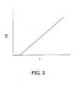
- the operation of the flow-regulating expansion valve 1 is described based on the flow rate characteristic in Fig. 3.
- the abscissa represents the value of the electric current i.
- the ordinate represents the flow rate Gf.
- the valve element 6 moves in valve-closing direction and reduces the effective pressure-receiving area to restrict the refrigerant flow rate, thereby holding the differential pressure (P2 - P3) at a constant level.
- the valve element 6 moves in valve-opening direction to increase the effective pressure-receiving area to increase the refrigerant flow rate, thereby holding the differential pressure (P2 - P3) across the orifice 51 at the constant level.
- the differential pressure (P2 - P3) is constantly controlled to a constant value according to the value of the electric current i.
- the pipe 2 does not only accommodate the internal structures including the flow-regulating mechanism, the movable core 4, and the fixed core 3, but also serves as a part of piping of the refrigeration cycle.
- the solenoid section 10 surrounds the pipe 2 from the outside, the flow-regulating mechanism is substantially integrated into the piping of the refrigeration cycle.
- the flow-regulating expansion valve 1 has a very simple and fair cost construction
- the flow-regulating expansion valve 201 has a hollow cylindrical pipe 202 accommodating a fixed core 203, a movable core 204, and a solid shaft 205.
- the solenoid section 10 surrounds the periphery of the pipe 202.
- the pipe 202 has enlarged opposite ends and caries the joints 70.
- the fixed core 203 has a hollow cylindrical body with the circumferentially peripheral groove 31.
- a bottomed cylindrical stopper 251 is fitted in a downstream end, for supporting a spring 281, and the solid shaft 205 from below.
- the stopper 251 has in an upstream-side bottom a communication hole 251 a forming a part of a refrigerant passage through the flow-regulating expansion valve 201.
- the rim of an opening in an upstream end of the fixed core 203 forms a valve seat 233.
- the movable core 204 has a stepped hollow cylindrical body the inner diameter of which is increased at an upstream end, and is disposed in the pipe 202 upstream of the fixed core 203.
- the movable core 204 has a tapered downstream end the outer diameter of which progressively decreases downstream and which forms a valve portion 241 for the valve seat 233.
- the movable core 204 has a small-bore part 242 and a large-bore part 243 upstream of the small-bore part 242, and the solid shaft 205 is inserted in these parts 242 and 243.
- a refrigerant passage 263 Between the movable core 204 and the inner wall of the pipe 202, there is formed a refrigerant passage 263.
- a non-magnetic member hollow cylinder 207 continuous with the movable core 204 extends downstream from the extreme end of the valve portion 241.
- the non-magnetic member 207 is inserted into the fixed core 203 and has at a downstream end circumferential a flange 271 extending radially outward to form a restriction 261 between the non-magnetic member 207 and the inner wall of the fixed core 203.
- a side wall of the non-magnetic member 207 has a through hole 272 of predetermined size, for introducing part of the refrigerant from an intermediate area 264 between the non-magnetic member 207 and the fixed core 203 into the member 207.
- the spring 281 (elastic member) between the downstream end face of the non-magnetic member 207 and the upstream end face of the stopper 251 urges the movable core 204 in upstream direction, i.e. in valve-opening direction via the non-magnetic member 207.
- the solenoid section 10 is de-energised, the movable core 204 is supported with a predetermined interspace by the fixed core 203.
- the solid shaft 205 is a stepped column.
- the lower end of a small-diameter part 252 is fixed to the upstream end face of the stopper 251.
- the small-diameter part 252 has the movable core 204 and the non-magnetic member 207 fitted thereon to guide them.
- a large-diameter part 253 formed in the upstream end of the solid shaft 205 not only guides the large-bore part 243 of the movable core 204, but also defines a predetermined inner space 262 between the junction (stepped portion) of the small-diameter part 252 and the large-diameter part 253, and the movable core 204.
- a polyimide film 291 (sealing member) is provided on the upstream end faces of the movable core 204 and of the solid shaft 205 in a manner hermetically covering these, thereby preventing refrigerant within the inner space 262 from flowing out upstream through a gap between the large-diameter part 253 and the inner wall of the movable core 204.
- Fig. 5 shows the open state
- Fig. 4 shows the fully-closed state
- High-pressure refrigerant from upstream is introduced through the refrigerant passage 263 and a refrigerant passage 265 between the valve portion 241 and the valve seat 233 into the intermediate area 264.
- the refrigerant is adiabatically expanded through the restriction 261 and flows downstream through the communication hole 251 a.
- Part of the refrigerant introduced into the intermediate area 264 is guided through the through hole 272 and a clearance between the solid shaft 205 and the movable core 204 into the inner space 262.
- the pressures in the intermediate area 264 and in the inner space 262 become equal.
- the pressure from upstream, which is prevailing immediately upstream of the refrigerant passage 265, is held equal to an inlet pressure. Therefore, part of pressure applied to the movable core 204 including the non-magnetic member 207 is cancelled.
- the pressure in a refrigerant inlet 221 is P1
- the pressure in the intermediate area 264 which has been reduced due to passage of the refrigerant through the refrigerant passage 265, is P2
- the pressure in a refrigerant outlet 222 which has been further reduced due to passage of the refrigerant through the restriction 261, is P3.
- the effective pressure-receiving area of the valve portion 241 in a seated state i.e. the cross-sectional area of the fixed core 203)
- the passage cross-sectional area of the restriction 261 is C.
- the parameters except the solenoid force f(i) are substantially fixed values, and therefore the flow rate Gf is held at a constant value proportional to the electric current i.
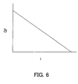
- the flow-regulating expansion valve 201 operates with a flow rate characteristic as shown in Fig. 6.
- the abscissa represents the value of the electric current I, and the ordinate represents the flow rate Gf.
- the valve portion 241 of the movable core 204 is in its open state due to the load fs of the spring 281 to hold the flow-regulating expansion valve 201 in a fully-open state.
- the flow rate Gf assumes a maximum value determined by the load fs.
- a differential pressure (P2 - P3) is generated across the restriction 261.
- the movable core 204 When the electric current i is supplied, the movable core 204 is moved in valve-closing direction to the position where the solenoid force f(i) and the load fs are balanced, and is stopped there.
- the differential pressure (P2 - P3) across the restriction 261 is held at a constant level, as described earlier.
- axial length of a large-diameter part 253' of a solid shaft 205' and that of the upstream end of the movable core 204' in which the large-diameter part 253' is inserted are each set to be equal to or larger than a predetermined length to increase the respective axial lengths of sliding surfaces of the two slidably fitted components, whereby leakage from the inner space 262 in the upstream direction is prevented or suppressed.
- the flow-regulating expansion valve 301 has a hollow cylindrical pipe 302 as a part of the piping of the refrigeration cycle.
- the pipe 302 accommodates a fixed core 303, a movable core 304, a solid shaft 305, and a hollow cylindrical member 306.
- the solenoid section 10 surrounds the periphery of the pipe 302.
- the fixed core 303 has a hollow cylindrical body of a predetermined inner diameter.
- One end of the solid shaft 305 is secured to the upstream end of the fixed core 303 in a suspended manner.
- the solid shaft 305 is a stepped cylinder and comprises a large-diameter part 351 with an outer diameter substantially equal to the inner diameter of the movable core 304, and with a small-diameter part 352 smaller in diameter than the large-diameter part 351.
- the large-diameter part 351 is located downstream of the fixed core 303, and the small-diameter part 352 extends through the fixed core 303 such that a refrigerant passage is formed.
- the upstream end of the small-diameter part 352 extends at right angles to the axis of the solid shaft 305, with its extreme end fixed to the fixed core 303.
- the movable core 304 has a stepped hollow cylindrical body in which an upstream part has an increased inner diameter, disposed in the pipe 302 downstream of the fixed core 303.
- the large-diameter part 351 is a guide for the movable core 304 and is inserted in a large-bore part 341 of the movable core 304.
- the movable core 304 downstream end is tapered with the outer diameter progressively decreasing downstream. The tapered downstream end forms a valve portion 343. Between the movable core 304 and the inner wall of the pipe 302, there is formed a clearance passage 371.
- the hollow cylindrical member 306 which is similar to the fixed core 303, has a circumferential peripheral groove 361. A portion of the pipe 302 is swaged into the fitting groove 361 from the outside. The rim of an opening in an upstream end of the hollow cylindrical member 306 forms a valve seat 362 for the valve portion 343.
- a bottomed hollow cylinder flow-reducing portion 345 extends downstream from the extreme end of the valve portion 343.
- a flange 346 projects radially outward from the extreme end of the flow-reducing portion 345.
- the flow-reducing portion 345 has in a side wall a communication hole 347 of predetermined size between an intermediate area 373 defined between the flow-reducing portion 345 and the hollow cylindrical member 306, and the small-bore part 342 of the movable core 304.
- a spring 381 (elastic member) between a stepped portion formed at the junction between the large-bore part 341 and the small-bore part 342 and the downstream end face of the solid shaft 304 urges the movable core 304 downstream, i.e. in valve-closing direction to close the valve when the solenoid section 10 is de-energised.
- Fig. 8 shows the non-energised state
- Fig. 9 shows the energised state.
- valve portion 343 Without electric current the valve portion 343 is seated on the valve seat 362 (fully-closed state).
- High-pressure refrigerant from upstream is introduced through a gap between the fixed core 303 and the movable core 304, the clearance passage 371, and the refrigerant passage 374 between the valve portion 343 and the valve seat 362 into the intermediate area 373.
- the refrigerant is adiabatically expanded through the restriction 372, and flows downstream.
- Part of the refrigerant introduced into the intermediate area 373 is also introduced through the communication hole 347 and the small-bore part 342 into an inner space 375 formed between the movable core 304 and the solid shaft 305.
- the pressures in the intermediate area 373 and in the inner space 375 become equal. At least a part of the pressure applied to the movable core 304 is cancelled.
- the pressure in a refrigerant inlet 321 is P1
- the pressure in the intermediate area 373, which has reduced due to passage of the refrigerant through the refrigerant passage 374 is P2
- the pressure in a refrigerant outlet 322, which has further reduced due to passage of the refrigerant through the restriction 372 is P3.
- the effective pressure-receiving area of the seated valve portion 343 i.e. the cross-sectional area of the hollow cylindrical member 306) is A
- the passage cross-sectional area of the restriction 372 is C.
- the flow-regulating expansion valve 401 has a hollow cylindrical pipe 202 accommodating a fixed core 403, a movable core 404, and a solid shaft 405.
- the solenoid section 10 surrounds the periphery of the pipe 202.
- the fixed core 403 has a hollow cylindrical body and is press-fitted into the pipe 202.
- the rim of an opening in a downstream end of the fixed core 403 forms a valve seat 431.
- a flange 432 protruding radially inward is formed at an axially intermediate portion.
- the movable core 404 has a stepped hollow cylindrical body the inner diameter of which is increased at a downstream end, and is disposed in the pipe 202 downstream of the fixed core 403.
- the movable core 404 has a tapered upstream end the outer diameter of which progressively decreases upstream.
- the tapered upstream end forms a valve portion 441 for the valve seat 431.
- the movable core 404 has a small-bore part 442 and a large-bore part 443 downstream of the small-bore part 442.
- the solid shaft 405 is inserted into the large-bore part 443. Between the movable core 404 and the inner wall of the pipe 202, there is formed a clearance passage 461.
- a pressure-equalizing pipe 409 (hollow cylinder) is fitted into the end of the valve portion 441 and extends into the fixed core 403.
- the extreme end of the pressure-equalizing pipe 409 reaches to a location slightly upstream of the flange 432 to form a restriction 462 between the flange 432 and the pressure-equalizing pipe 409.
- a spring 481 (elastic member) between the flange 432 and the upstream end face of the movable core 404, with opposite ends fixed to the fixed core 403 and the movable core 404, respectively, supports the movable core 404 with a predetermined interspace by the fixed core 403 when the solenoid section 10 is de-energised.
- the solid shaft 405 is a stepped column, with a large-diameter part 451 fitted in the large-bore part 443 of the movable core 404 to guide the movable core 404.
- a continuous small-diameter part 452 downstream of the large-diameter part 451 is fixed with the lower end to a disk-shaped stopper 407 rigidly press-fitted into the pipe 202.
- the stopper 407 has an axial communication hole 471 forming a part of a refrigerant passage.
- an inner space 463 communicating with the refrigerant passage via the small-bore part 442 and the pressure-equalizing pipe 409.
- the cross-sectional area of the inner space 463 is equal to that of the lower end of an intermediate area 464.
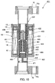
- Fig. 11 shows the open state
- Fig. 10 shows the fully-closed state
- valve portion 441 is held away from the valve seat 431.
- the flow-regulating expansion valve 401 is in the open state.
- High-pressure refrigerant from upstream is adiabatically expanded through the restriction 462 and reaches the intermediate area 464. Further, the refrigerant passes through a refrigerant passage 465 between the valve portion 441 and the valve seat 431, and the clearance passage 461, and flows downstream through the communication hole 471.
- the pressure in the. inner space 463 is equal to an inlet pressure via the pressure-equalizing pipe 409, and hence part of refrigerant pressure applied to the movable core 404 including the pressure-equalizing pipe 409 is cancelled.
- the pressure in a refrigerant inlet 421 is P1
- the pressure in the intermediate area 464, which has been reduced due to passage through the restriction 462 is P2
- the pressure in a refrigerant outlet 422, which has been further reduced due to passage through the refrigerant passage 465 is P3.
- the effective pressure-receiving area of the seated valve portion 441 i.e. the cross-sectional area of the lower end of the intermediate area 464, which is equal to that of the inner space 463) is A
- the cross-sectional area of a circle having the outer diameter of the pressure-equalizing pipe 409 B
- the passage cross-section of the restriction 462 is C.
- the solenoid force generated by the electric current i is f(i), and the load of the spring 481, which acts in the upstream direction, is fs.
- the parameters except the solenoid force f(i) are substantially fixed values, and therefore the flow rate Gf is held at a constant value proportional to the electric current i.
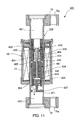
- the pressure-equalizing pipe 409 extends from the movable core 404 such that the restriction 462 is formed between the pressure-equalizing pipe 409 and the flange 432, a variation as shown in Fig. 12 can also be employed.
- a passage pipe 409' extending into the inner space 463 of the movable core 404' is rigidly fitted in the flange 432 of the fixed core 403.
- a restriction 462' is formed between the passage pipe 409' and the inner wall of a small-bore part 442' of the movable core 404'.
- High-pressure refrigerant from upstream is adiabatically expanded through the restriction 462' via the inner space 463. Then, the refrigerant passes through the refrigerant passage 465 between the valve portion 441 and the valve seat 431, and the clearance passage 461, and flows downstream through the communication hole 471.
- the flow-regulating expansion valve 501 has a hollow cylinder pipe 202 accommodating a fixed core 503, a movable core 504, and a solid shaft 505.
- the solenoid section 10 surrounds the periphery of the pipe 202.
- the fixed core 503 has a hollow cylindrical body and is press-fitted into the pipe 202.
- the rim of an opening in an upstream end of the fixed core 503 forms a valve seat 531, and the inner diameter is slightly reduced downstream of the valve seat 531 to form a stepped portion 532.
- the stepped portion 532 contains a disk-shaped stopper 507.
- the stopper 507 has an axial communication hole 571 as a part of a refrigerant passage.
- the movable core 504 has a stepped hollow cylinder body the inner diameter of which is increased at an upstream end, and is disposed in the pipe 202 upstream of the fixed core 503.
- the movable core 504 downstream end is tapered such that the outer diameter progressively decreases downstream.
- the tapered downstream end forms a valve portion 541 for the valve seat 531.
- the movable core 504 has a large-bore part 542 and a small-bore part 543 downstream of the large-bore part 542, through which the solid shaft 505 extends.
- a restriction 561 is formed between the movable core 504 and the inner wall of the pipe 202.
- the movable core 504 has a flat face orthogonal to the axis at a downstream extreme end.
- a spring 581 (elastic member) between the flat face and the upstream end face of the stopper 507 acts such that the movable core 504 is supported with a predetermined interspace by the fixed core 503 in the de-energised state.
- the solid shaft 505 is a stepped column, and the lower end of a small-diameter part 552 is fixed to the upstream end face of the stopper 507.
- the small-diameter part 552 guides the movable core 504.
- a large-diameter part 551 in the upstream end of the solid shaft 505 guides the large-bore part of the movable core 504, and defines a predetermined inner space 562 between a stepped portion formed at the junction between the small-diameter part 552 and the large-diameter part 551 of the solid shaft 505 and the movable core 504.
- a hermetically sealing polyimide film 291 is provided on the upstream end face of the movable core 504 and the upstream end face of the solid shaft 505.
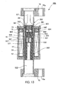
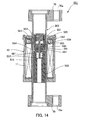
- Fig. 13 shows the open state
- Fig. 14 shows the fully-closed state
- valve portion 541 is held away from the valve seat 531 to hold the flow-regulating expansion valve 501 in its open state.
- High-pressure refrigerant from upstream is adiabatically expanded through the restriction 561 and is introduced into an intermediate area 564.
- the refrigerant also flows downstream via a refrigerant passage 565 between the valve portion 541 and the valve seat 531, and the communication hole 571.
- Part of the refrigerant passing through the intermediate area 564 is introduced through a clearance between the small-diameter part 552 and the movable core 504 into the inner space 562.
- An outlet pressure downstream of the intermediate area 564 and the pressure in the inner space 562 become equal. Part of the pressures applied to the movable core 504 is cancelled.
- the pressure at a refrigerant inlet 521 P1 is the pressure in the intermediate area 564, which has been reduced due to passage of the refrigerant through the restriction 561 is P2, and the pressure in a refrigerant outlet 522, which has been further reduced due to passage of the refrigerant through the refrigerant passage 565 is P3.
- the effective pressure-receiving area of the seated valve portion 541 i.e. the cross-sectional area of the inner space 562) is A
- the area of the circle having the outer diameter of the upstream end face of the movable core 504 is B
- the passage cross-sectional area of the restriction 561 is C.
- the solenoid force generated by the electric current i is f(i), and the load of the spring 581, which acts in the upstream direction, is fs.
- the parameters except the solenoid force f(i) are substantially fixed values, and therefore the flow rate Gf is held at a constant value proportional to the electric current i.
- the flow-regulating expansion valve 601 has the hollow cylinder pipe 202 accommodating a fixed core 603, a movable core 604, and a hollow cylindrical member 605.
- the solenoid section 10 surrounds the periphery of the pipe 202.
- the fixed core 603 has a bottomed hollow cylinder body having the bottom at the upstream end. The body is press-fitted into the pipe 202.
- the fixed core 603 has a circular recess 631 at the upstream end, for accommodating a part of a spring 681.
- a valve seat 632 is integrally formed with the rim of an opening of the recess 631, protruding upstream.
- a communication hole 634 is provided in the side wall of the upstream end of the fixed core 603 between an internal refrigerant passage 633 and the upstream side.
- the movable core 604 has a stepped hollow cylinder body which has a stepped portion at its downstream end, disposed in the pipe 202 upstream of the fixed core 603.
- the movable core 604 has a large-bore part slidably fitted on a hollow cylindrical shaft part extending downstream from the hollow cylindrical member 605 fixed in the pipe 202 further upstream of the movable core 604.
- a circular restriction 643 In the centre of the stepped portion of the movable core 604, i.e. in the bottom of the large-bore part, is a circular restriction 643.
- the downstream end face of the movable core 604 in which the restriction 643 opens has a flat portion for the spring 681, and a tapered portion the diameter of which progressively increases downstream forms a valve portion 641 for the valve seat 632.
- the spring 681 (elastic member) is interposed between the downstream end face of the movable core 604 and the recess 631 of the fixed core 603. In de-energised state, the movable core 604 is supported with a predetermined interspace by the fixed core 603. Between the movable core 604 and the pipe 202 is a predetermined clearance 661.
- Fig. 15 shows the open state
- Fig. 16 shows the fully-closed state.
- valve portion 641 In Fig. 16, (de-energised state) the valve portion 641 is held away from the valve seat 632.
- the flow-regulating expansion valve 601 is in the fully-open state.
- valve portion 641 When electric current i is supplied, a solenoid force is generated. A force acting in the direction of seating the valve portion 641 against the urging force of the spring 681 is generated. The valve portion 641 is held in a position where the solenoid force and the load of the spring 681 are balanced. A predetermined passage cross-section is formed between the valve portion 641 and the valve seat 632.
- High-pressure refrigerant from upstream is adiabatically expanded through the restriction 643 and is then introduced into an intermediate area 664 between the downstream end face of the movable core 604 and the recess 631 of the fixed core 603. Further, the refrigerant flows downstream via a refrigerant passage 665 between the valve portion 641 and the valve seat 632, the communication hole 634, and the internal refrigerant passage 633.
- the pressure at a refrigerant inlet 621 is P1
- the pressure in the intermediate area 664 which has been reduced due to passage of the refrigerant through the restriction 643
- P2 the pressure in a refrigerant outlet 622, which has been further reduced due to passage of the refrigerant through the refrigerant passage 665
- the effective pressure-receiving area of the seated valve portion 641 i.e. the cross-sectional area of the movable core 604
- the passage cross-sectional area of the restriction 643 is C.
- the solenoid force generated is f(i), and the load of the spring 681, which acts in the upstream direction, is fs.
- the parameters except the solenoid force f(i) are substantially fixed values, and therefore the flow rate Gf is held at a constant value proportional to the electric current i supplied to the solenoid coil 11.
Abstract
Description
- The present invention relates to a flow-regulating expansion valve according to the preamble of
claim 1. - A known flow-regulating expansion valve (JP-A-2001-153495) in a refrigeration cycle of an automotive air conditioner decompresses refrigerant by adiabatically expansion, but also electrically controls the flow rate. The flow-regulating mechanism is integrated into a body block separate from piping constituting a refrigerant passage of a refrigeration cycle. A high-pressure refrigerant inlet passage and an expanded refrigerant outlet passage are provided. The differential pressure across the differential pressure control expansion valve is controlled by a solenoid to hold the flow rate at a predetermined constant level. The arrangement occupies much mounting space because the body block is separate from the piping of the refrigeration cycle. Further, the internal refrigerant passage where internal structures of the flow-regulating mechanism, such as a restriction and a valve element, are arranged, and the solenoid section for the internal structures are separately disposed in the body block. The positioning of the high-pressure refrigerant inlet passage, the expanded refrigerant outlet passage, and the connecting internal refrigerant passage according as well as the design of the flow-regulating mechanism and also the positioning of joints with the piping of the refrigeration cycle, are complicated and negatively influence the manufacturing costs.
- It is an object of the invention to provide a flow-regulating expansion valve which is compact in size and may be realized at low cost.
- The object is achieved with the features of
claim 1. - Here, the "pipe" may be, for example, one exclusively used for the flow-regulating expansion valve, and is connected to the piping of the refrigeration cycle by a joint or the like, or alternatively, may already be a part of the piping of the refrigeration cycle. The "predetermined reference position of the movable core" is a position which assures that the flow rate is equal to the preset constant flow rate, and means a position where a balance occurs between the internal pressures and the urging forces applied to the movable core.
- In the expansion valve, the movable core is moved relative to the fixed core by energizing or de-energizing the solenoid coil. This causes the valve-opening and valve-closing operations of the flow-regulating mechanism for adjusting the size of the internal passage cross-section. The refrigerant is expanded or decompressed by the flow-regulating mechanism corresponding to the co-action between the operation of the fixed and movable cores, and is delivered at a constant flow rate according to the value of the electric current supplied to the solenoid coil. The pipe forming the body does not only accommodate the internal structures, such as the flow-regulating mechanism, the fixed core, and the movable core, but also serves as a part of the piping of the refrigeration cycle. The solenoid coil surrounds the pipe so that a structure, such as the mentioned body block can be dispensed with. Therefore, a substantial integration of the flow-regulating mechanism into the piping of the refrigeration cycle can be achieved. The flow-regulating expansion valve is very simple in construction. As the flow-regulating expansion valve is integrated in the piping of the refrigeration cycle, considerable mounting space for the flow-regulating expansion valve can be saved. The size of the flow-regulating expansion valve, a resulting reduction of material costs and manufacturing costs lower the costs of the flow-regulating expansion valve.
- Embodiments of the invention will be described with reference to the drawings.
- Fig. 1:
- a cross-section of a first embodiment of a flow-regulating expansion valve in closed state,
- Fig. 2:
- a cross-section view of the first embodiment, in an open state,
- Fig. 3:
- a diagram of the relation between the flow rate and the current of the first embodiment,
- Fig. 4:
- a cross-section of a second embodiment, in one state,
- Fig. 5:
- a cross-section of the second embodiment, in another state,
- Fig. 6:
- a diagram of flow rate characteristics of the second embodiment,
- Fig. 7:
- a cross-section of a variation of the second embodiment,
- Fig. 8:
- a cross-section of a third embodiment, in one state,
- Fig. 9:
- a cross-section of the third embodiment, in another state,
- Fig. 10:
- a cross-section of a fourth embodiment, in one state,
- Fig. 11:
- a cross-section of the fourth embodiment, in another state,
- Fig. 12:
- a cross-section of a variation of the fourth embodiment,
- Fig. 13:
- a cross-section of a fifth embodiment, in one state,
- Fig. 14:
- a cross-section of the fifth embodiment, in another state,
- Fig. 15:
- a cross-section of a sixth embodiment, in one state, and
- Fig. 16:
- a cross section of the sixth embodiment, in another state.
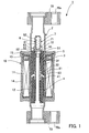
- In Figs 1 and 2 a flow-regulating
expansion valve 1 comprises a hollow cylindrical body formed by apipe 2 having opposite open ends, afixed core 3, amovable core 4, ahollow member 5, and avalve element 6, accommodated in thepipe 2, and asolenoid section 10 surrounding the periphery of thepipe 2. -
Piping joints 70 of a generally oval shape are attached to the ends of thepipe 2. Each end is formed with a contracted part. The diameter of the contracted part is expanded after thepiping joint 70 is fitted on thepipe 2. Thepiping joint 70 has a throughhole 70a at a location outward of thepipe 2 for a bolt. - To connect the flow-regulating
expansion valve 1 to the piping of the not shown refrigeration cycle, piping joints like thepiping joint 70 are provided on opposed pipes. Associated piping joints are put into each other via an O ring, and are fixed to each other by inserting a bolt through the through holes and tightening a nut. Thepipe 2 then forms part of a refrigerant passage. Thefixed core 3 has a hollow cylindrical body with acircumferential groove 31. A downstream end of the fixedcore 3 has an inner diameter increased by a predetermined amount to form achamber 32 for aspring 81. The rim of an opening in an upstream end of the fixedcore 3 forms avalve seat 33 for thevalve element 6. The fixed core is fixed 3 in thepipe 2 by swaging a portion of thepipe 2 from the outside into thegroove 31. - An upstream end face of the fixed
core 3, there is mounted ahollow shaft 7 in the form of a bottomed and stepped hollow cylinder, which is closed on the upstream side. Thehollow shaft 7 is expanded atpart 71 and is mounted on the fixedcore 3 such that an extreme end of the expandedpart 71 surrounds the upstream-side opening of the fixedcore 3. Thehollow shaft 7 communicates with a refrigerant passage formed by thehollow member 5. The expandedpart 71 has apredetermined opening 72 in a side surface for introducing refrigerant from upstream. - The
movable core 4 has a hollow cylindrical body and is movably disposed in thepipe 2 of the fixedcore 3. An upstream end of themovable core 4 has an increased inner diameter to form achamber 41 for the spring 81 (elastic member) between the fixed and themovable cores spring 81 extends through thechamber 32 into the fixedcore 3 and through thechamber 41 into themovable core 4. The spring ends are fixed to the fixed andmovable cores solenoid section 10 is not energized, themovable core 4 is supported with a predetermined interspace by the fixedcore 3. - The
hollow member 5 has a hollow cylindrical body with a downstream part inserted and rigidly fitted into themovable core 4. An upstream part is slidably fitted into the fixedcore 3. Thehollow member 5 has an upstream end restricted to form an orifice 51 (restriction) of a fixed passage cross-section. Thehollow member 5 has threecylindrical support portions 52 extending upward from an upstream end face at circumferential intervals of 120 degrees, for supporting avalve portion 62, and also has a throughhole 53 in a side wall so that a refrigerant pressure generated by moving themovable core 4 and thehollow member 5 in an area defined by the fixed core 3is released via the throughhole 53 into the internal refrigerant passage. - The
valve element 6 has a hollow cylindrical body and comprises aguide portion 61 hermetically guided by thehollow shaft 7, and thevalve portion 62 continuously provided on the downstream side of theguide portion 61. Thevalve portion 62 can be seated on thevalve seat 33 and has a larger outer diameter than theguide portion 61, and has tapered shape the diameter of which progressively decreases toward the downstream end. Asmaller communication hole 63 than the inner diameter of theguide portion 61 extends axially through thevalve portion 62 between the insides of theguide portion 61 and of thehollow shaft 7. Thehollow shaft 7 contains anaxial spring 82. The downstream spring end is held in contact with the upstream end face of thevalve portion 62 and urges thevalve element 6 downstream to constantly hold the downstream end face of thevalve portion 62 in contact with the upstream end faces of thesupport portions 52 of thehollow member 5. - The
solenoid section 10 is generally cylindrical and surrounds thepipe 2 from the outside. Afirst bobbin 12 with asolenoid coil 11 is disposed around the periphery of thepipe 2. On the upstream end of thefirst bobbin 12 is disposed asecond bobbin 13 which forms with the first bobbin 12 a passage for a lead wire to a terminal of thesolenoid coil 11. Thebobbins first yoke 14. The upstream end of thefirst yoke 14 is closed by asecond yoke 15 to form a continuous magnetic circuit. - Fig. 1 shows a state of the
de-energised solenoid coil 11, while Fig. 2 shows energised a state. - In Fig. 1, the
valve element 6 is seated on thevalve seat 33. The flow-regulatingexpansion valve 1 is in a fully-closed state. - When electric current i (Fig. 2) is supplied to the
solenoid coil 11, a solenoid force is generated, the magnitude of which corresponds to the value of the electric current i. Themovable core 4 is attracted toward the fixedcore 3. A force moves thevalve element 6 upward via thehollow member 5 against the urging forces of thesprings valve element 6 is held in a position where the solenoid force and the loads of thesprings valve element 6 and thevalve seat 33. - High-pressure refrigerant from upstream is guided through the
opening 72 of thehollow shaft 7, arefrigerant passage 65 between thevalve element 6 and thevalve seat 33, and gaps between adjacent pairs ofsupport portions 52 into anintermediate area 55 immediately upstream of the upstream-side opening of thehollow member 5. The refrigerant is adiabatically expanded while passing through theorifice 51. - The refrigerant is also introduced through the
communication hole 63 into aninner area 75 between thevalve element 6 and thehollow shaft 7. The pressures in theintermediate area 55 and in theinner area 75 become equal to nullify or cancel the effect of the pressure or thevalve element 6. Thehollow member 5 only receives the load of thespring 82 from thevalve element 6. - The pressure in a
refrigerant inlet 21 is P1; the pressure in theintermediate area 55, which has been reduced due to passage of the refrigerant through therefrigerant passage 65, is P2, and the pressure in arefrigerant outlet 22, which pressure has been further reduced by the passage of the refrigerant through theorifice 51, is P3,. The effective pressure-receiving area of thevalve portion 62 in the seated state (i.e. the passage cross-sectional area of the inner area 55) is A, and the passage cross-sectional area of theorifice 51 is C. The flow rate Gf is: - The solenoid force generated by the electric current i is f(i), and the sum of the forces of the
springs hollow member 5 in upstream and downstream directions is - From (1) and (2), the flow rate Gf is:
- In the right side of (3), the parameters except the solenoid force f(i) are substantially fixed values, and therefore the flow rate Gf is held at a constant value proportional to the electric current i.
- The operation of the flow-regulating
expansion valve 1 is described based on the flow rate characteristic in Fig. 3. The abscissa represents the value of the electric current i. The ordinate represents the flow rate Gf. When the electric current i is zero, thevalve element 6 is seated on thevalve seat 33 due to the load fs. The flow-regulatingexpansion valve 1 is in a fully-closed state. The flow rate Gf is zero. - When a current i of e.g. 0.3 A is supplied to the
solenoid coil 11, and a solenoid force f(i) larger than the load fs of the springs is applied to thehollow member 5, thevalve element 6 is immediately moved from the seated position to the position where the solenoid force f(i) and the load fs are balanced, and is stopped there. Refrigerant starts to flow, and a differential pressure (P2 - P3) is generated across theorifice 51. - When the refrigerant flow rate on the upstream side of the refrigeration cycle is increased to raise the pressure P1 in the
refrigerant inlet 21, thevalve element 6 moves in valve-closing direction and reduces the effective pressure-receiving area to restrict the refrigerant flow rate, thereby holding the differential pressure (P2 - P3) at a constant level. When the refrigerant flow rate from upstream is reduced to lower the pressure P1 in therefrigerant inlet 21, thevalve element 6 moves in valve-opening direction to increase the effective pressure-receiving area to increase the refrigerant flow rate, thereby holding the differential pressure (P2 - P3) across theorifice 51 at the constant level. The differential pressure (P2 - P3) is constantly controlled to a constant value according to the value of the electric current i. - The
pipe 2 does not only accommodate the internal structures including the flow-regulating mechanism, themovable core 4, and the fixedcore 3, but also serves as a part of piping of the refrigeration cycle. As thesolenoid section 10 surrounds thepipe 2 from the outside, the flow-regulating mechanism is substantially integrated into the piping of the refrigeration cycle. Hence the flow-regulatingexpansion valve 1 has a very simple and fair cost construction - In Figs 4 and 5, the flow-regulating
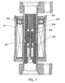
expansion valve 201 has a hollowcylindrical pipe 202 accommodating afixed core 203, amovable core 204, and asolid shaft 205. Thesolenoid section 10 surrounds the periphery of thepipe 202. Thepipe 202 has enlarged opposite ends and caries thejoints 70. - The fixed
core 203 has a hollow cylindrical body with the circumferentiallyperipheral groove 31. A bottomedcylindrical stopper 251 is fitted in a downstream end, for supporting aspring 281, and thesolid shaft 205 from below. Thestopper 251 has in an upstream-side bottom acommunication hole 251 a forming a part of a refrigerant passage through the flow-regulatingexpansion valve 201. The rim of an opening in an upstream end of the fixedcore 203 forms avalve seat 233. - The
movable core 204 has a stepped hollow cylindrical body the inner diameter of which is increased at an upstream end, and is disposed in thepipe 202 upstream of the fixedcore 203. Themovable core 204 has a tapered downstream end the outer diameter of which progressively decreases downstream and which forms avalve portion 241 for thevalve seat 233. Themovable core 204 has a small-bore part 242 and a large-bore part 243 upstream of the small-bore part 242, and thesolid shaft 205 is inserted in theseparts movable core 204 and the inner wall of thepipe 202, there is formed arefrigerant passage 263. A non-magnetic memberhollow cylinder 207 continuous with themovable core 204 extends downstream from the extreme end of thevalve portion 241. - The
non-magnetic member 207 is inserted into the fixedcore 203 and has at a downstream end circumferential aflange 271 extending radially outward to form arestriction 261 between thenon-magnetic member 207 and the inner wall of the fixedcore 203. A side wall of thenon-magnetic member 207 has a throughhole 272 of predetermined size, for introducing part of the refrigerant from anintermediate area 264 between thenon-magnetic member 207 and the fixedcore 203 into themember 207. - The spring 281 (elastic member) between the downstream end face of the
non-magnetic member 207 and the upstream end face of thestopper 251 urges themovable core 204 in upstream direction, i.e. in valve-opening direction via thenon-magnetic member 207. When thesolenoid section 10 is de-energised, themovable core 204 is supported with a predetermined interspace by the fixedcore 203. - The
solid shaft 205 is a stepped column. The lower end of a small-diameter part 252 is fixed to the upstream end face of thestopper 251. The small-diameter part 252 has themovable core 204 and thenon-magnetic member 207 fitted thereon to guide them. A large-diameter part 253 formed in the upstream end of thesolid shaft 205 not only guides the large-bore part 243 of themovable core 204, but also defines a predeterminedinner space 262 between the junction (stepped portion) of the small-diameter part 252 and the large-diameter part 253, and themovable core 204. - Further, a polyimide film 291 (sealing member) is provided on the upstream end faces of the
movable core 204 and of thesolid shaft 205 in a manner hermetically covering these, thereby preventing refrigerant within theinner space 262 from flowing out upstream through a gap between the large-diameter part 253 and the inner wall of themovable core 204. - Fig. 5 shows the open state, while Fig. 4 shows the fully-closed state.
- In Fig. 5, (de-energised sate) the
valve portion 241 is held away from thevalve seat 233. The flow-regulatingexpansion valve 201 is in its open state. - When an electric current i is supplied to the
solenoid coil 11, a solenoid force the magnitude of which corresponds to the value of the electric current i is generated. Themovable core 204 is attracted toward the fixedcore 203. The force acts in the direction of seating thevalve portion 241 against the urging force of thespring 281. Thevalve portion 241 is held in a position where the solenoid force and the load of thespring 281 are balanced. A predetermined passage cross-section is formed between thevalve portion 241 and thevalve seat 233. - High-pressure refrigerant from upstream is introduced through the
refrigerant passage 263 and arefrigerant passage 265 between thevalve portion 241 and thevalve seat 233 into theintermediate area 264. The refrigerant is adiabatically expanded through therestriction 261 and flows downstream through thecommunication hole 251 a. - Part of the refrigerant introduced into the
intermediate area 264 is guided through the throughhole 272 and a clearance between thesolid shaft 205 and themovable core 204 into theinner space 262. The pressures in theintermediate area 264 and in theinner space 262 become equal. The pressure from upstream, which is prevailing immediately upstream of therefrigerant passage 265, is held equal to an inlet pressure. Therefore, part of pressure applied to themovable core 204 including thenon-magnetic member 207 is cancelled. - The pressure in a
refrigerant inlet 221 is P1, the pressure in theintermediate area 264, which has been reduced due to passage of the refrigerant through therefrigerant passage 265, is P2, and the pressure in arefrigerant outlet 222, which has been further reduced due to passage of the refrigerant through therestriction 261, is P3. The effective pressure-receiving area of thevalve portion 241 in a seated state (i.e. the cross-sectional area of the fixed core 203) is A, and the passage cross-sectional area of therestriction 261 is C. The flow rate Gf is: - The solenoid force generated by the electric current i is f(i), and the load of the
spring 281, which acts in the upstream direction, is fs. The relationship between the forces acting on thenon-magnetic member 207 and themovable core 204 in the upstream and downstream directions is then: - From (4) and (5), the flow rate Gf is:
- In the right side (6), the parameters except the solenoid force f(i) are substantially fixed values, and therefore the flow rate Gf is held at a constant value proportional to the electric current i.
- The flow-regulating
expansion valve 201 operates with a flow rate characteristic as shown in Fig. 6. The abscissa represents the value of the electric current I, and the ordinate represents the flow rate Gf. When the electric current i is zero, thevalve portion 241 of themovable core 204 is in its open state due to the load fs of thespring 281 to hold the flow-regulatingexpansion valve 201 in a fully-open state. The flow rate Gf assumes a maximum value determined by the load fs. When the refrigerant flows, a differential pressure (P2 - P3) is generated across therestriction 261. - When the electric current i is supplied, the
movable core 204 is moved in valve-closing direction to the position where the solenoid force f(i) and the load fs are balanced, and is stopped there. - The differential pressure (P2 - P3) across the
restriction 261 is held at a constant level, as described earlier. - When the electric current i exceeds a predetermined value, the flow-regulating
expansion valve 201 is fully closed (Fig. 4). - Although the
polyimide film 291 is mentioned covering the upstream end faces of themovable core 204 and of thesolid shaft 205, it is possible to dispense with such a sealing member, as shown in Fig. 7. - There the axial length of a large-diameter part 253' of a solid shaft 205' and that of the upstream end of the movable core 204' in which the large-diameter part 253' is inserted are each set to be equal to or larger than a predetermined length to increase the respective axial lengths of sliding surfaces of the two slidably fitted components, whereby leakage from the
inner space 262 in the upstream direction is prevented or suppressed. - In Figs 8; and 9 the flow-regulating
expansion valve 301 has a hollowcylindrical pipe 302 as a part of the piping of the refrigeration cycle. Thepipe 302 accommodates a fixedcore 303, amovable core 304, asolid shaft 305, and a hollowcylindrical member 306. Thesolenoid section 10 surrounds the periphery of thepipe 302. The fixedcore 303 has a hollow cylindrical body of a predetermined inner diameter. One end of thesolid shaft 305 is secured to the upstream end of the fixedcore 303 in a suspended manner. - The
solid shaft 305 is a stepped cylinder and comprises a large-diameter part 351 with an outer diameter substantially equal to the inner diameter of themovable core 304, and with a small-diameter part 352 smaller in diameter than the large-diameter part 351. The large-diameter part 351 is located downstream of the fixedcore 303, and the small-diameter part 352 extends through the fixedcore 303 such that a refrigerant passage is formed. The upstream end of the small-diameter part 352 extends at right angles to the axis of thesolid shaft 305, with its extreme end fixed to the fixedcore 303. - The
movable core 304 has a stepped hollow cylindrical body in which an upstream part has an increased inner diameter, disposed in thepipe 302 downstream of the fixedcore 303. The large-diameter part 351 is a guide for themovable core 304 and is inserted in a large-bore part 341 of themovable core 304. Downstream of the large-bore part 341, there is formed a small-bore part 342 smaller in inner diameter than the large-bore part 341, for communication with the downstream side. Themovable core 304 downstream end is tapered with the outer diameter progressively decreasing downstream. The tapered downstream end forms avalve portion 343. Between themovable core 304 and the inner wall of thepipe 302, there is formed aclearance passage 371. - The hollow
cylindrical member 306, which is similar to the fixedcore 303, has a circumferentialperipheral groove 361. A portion of thepipe 302 is swaged into thefitting groove 361 from the outside. The rim of an opening in an upstream end of the hollowcylindrical member 306 forms avalve seat 362 for thevalve portion 343. - A bottomed hollow cylinder flow-reducing
portion 345 extends downstream from the extreme end of thevalve portion 343. Aflange 346 projects radially outward from the extreme end of the flow-reducingportion 345. Between theflange 346 and the inner wall of the hollowcylindrical member 306, there is formed arestriction 372. The flow-reducingportion 345 has in a side wall acommunication hole 347 of predetermined size between anintermediate area 373 defined between the flow-reducingportion 345 and the hollowcylindrical member 306, and the small-bore part 342 of themovable core 304. - A spring 381 (elastic member) between a stepped portion formed at the junction between the large-
bore part 341 and the small-bore part 342 and the downstream end face of thesolid shaft 304 urges themovable core 304 downstream, i.e. in valve-closing direction to close the valve when thesolenoid section 10 is de-energised. - Fig. 8 shows the non-energised state, while Fig. 9 shows the energised state.
- Without electric current the
valve portion 343 is seated on the valve seat 362 (fully-closed state). - When an electric current i is supplied to the
solenoid coil 11, a solenoid force the magnitude of which corresponds to the value of the electric current i is generated. Themovable core 304 is attracted toward the fixedcore 303. Thevalve portion 343 is held in a position where the solenoid force and the load of thespring 381 are balanced. A predetermined passage cross-section is formed between thevalve portion 343 and thevalve seat 362. - High-pressure refrigerant from upstream is introduced through a gap between the fixed
core 303 and themovable core 304, theclearance passage 371, and therefrigerant passage 374 between thevalve portion 343 and thevalve seat 362 into theintermediate area 373. The refrigerant is adiabatically expanded through therestriction 372, and flows downstream. - Part of the refrigerant introduced into the
intermediate area 373 is also introduced through thecommunication hole 347 and the small-bore part 342 into aninner space 375 formed between themovable core 304 and thesolid shaft 305. The pressures in theintermediate area 373 and in theinner space 375 become equal. At least a part of the pressure applied to themovable core 304 is cancelled. - The pressure in a
refrigerant inlet 321 is P1, the pressure in theintermediate area 373, which has reduced due to passage of the refrigerant through therefrigerant passage 374 is P2, and the pressure in arefrigerant outlet 322, which has further reduced due to passage of the refrigerant through therestriction 372 is P3. The effective pressure-receiving area of the seated valve portion 343 (i.e. the cross-sectional area of the hollow cylindrical member 306) is A, and the passage cross-sectional area of therestriction 372 is C. The flow rate Gf is: - The solenoid force generated by the electric current i is f(i), and the load of the
spring 381, which acts in the upstream direction, is fs, and the relationship between the forces acting on themovable core 304 in the upstream and downstream directions is represented by the following equation: - From (7) and (8), the flow rate Gf is:
- In the right side of (9), the parameters except the solenoid force f(i) are substantially fixed values, and therefore the flow rate Gf is held at a constant value proportional to the electric current i.
- In Figs 10, 11,, the flow-regulating
expansion valve 401 has a hollowcylindrical pipe 202 accommodating afixed core 403, amovable core 404, and asolid shaft 405. Thesolenoid section 10 surrounds the periphery of thepipe 202. - The fixed
core 403 has a hollow cylindrical body and is press-fitted into thepipe 202. The rim of an opening in a downstream end of the fixedcore 403 forms avalve seat 431. Aflange 432 protruding radially inward is formed at an axially intermediate portion. - The
movable core 404 has a stepped hollow cylindrical body the inner diameter of which is increased at a downstream end, and is disposed in thepipe 202 downstream of the fixedcore 403. Themovable core 404 has a tapered upstream end the outer diameter of which progressively decreases upstream. The tapered upstream end forms avalve portion 441 for thevalve seat 431. Themovable core 404 has a small-bore part 442 and a large-bore part 443 downstream of the small-bore part 442. Thesolid shaft 405 is inserted into the large-bore part 443. Between themovable core 404 and the inner wall of thepipe 202, there is formed aclearance passage 461. - A pressure-equalizing pipe 409 (hollow cylinder) is fitted into the end of the
valve portion 441 and extends into the fixedcore 403. The extreme end of the pressure-equalizingpipe 409 reaches to a location slightly upstream of theflange 432 to form arestriction 462 between theflange 432 and the pressure-equalizingpipe 409. A spring 481 (elastic member) between theflange 432 and the upstream end face of themovable core 404, with opposite ends fixed to the fixedcore 403 and themovable core 404, respectively, supports themovable core 404 with a predetermined interspace by the fixedcore 403 when thesolenoid section 10 is de-energised. - The
solid shaft 405 is a stepped column, with a large-diameter part 451 fitted in the large-bore part 443 of themovable core 404 to guide themovable core 404. A continuous small-diameter part 452 downstream of the large-diameter part 451 is fixed with the lower end to a disk-shapedstopper 407 rigidly press-fitted into thepipe 202. Thestopper 407 has anaxial communication hole 471 forming a part of a refrigerant passage. Between a stepped portion at the junction of the large-bore part 443 of themovable core 404 and the small-bore part 442 and the upstream end face of thesolid shaft 405, there is formed aninner space 463 communicating with the refrigerant passage via the small-bore part 442 and the pressure-equalizingpipe 409. The cross-sectional area of theinner space 463 is equal to that of the lower end of anintermediate area 464. - Fig. 11 shows the open state, while Fig. 10 shows the fully-closed state.
- In Fig. 11, (de-energised state) the
valve portion 441 is held away from thevalve seat 431. The flow-regulatingexpansion valve 401 is in the open state. - When an electric current i is supplied, a solenoid force the magnitude of which corresponds to the value of the electric current i is generated. The
movable core 404 is attracted toward the fixedcore 403. A force acting in the direction of seating thevalve portion 441 against the urging force of thespring 481 is generated. Thevalve portion 441 is held in a position where the solenoid force and the load of thespring 481 are balanced. A predetermined passage cross-section is formed between thevalve portion 441 and thevalve seat 431. - High-pressure refrigerant from upstream is adiabatically expanded through the
restriction 462 and reaches theintermediate area 464. Further, the refrigerant passes through arefrigerant passage 465 between thevalve portion 441 and thevalve seat 431, and theclearance passage 461, and flows downstream through thecommunication hole 471. - The pressure in the.
inner space 463 is equal to an inlet pressure via the pressure-equalizingpipe 409, and hence part of refrigerant pressure applied to themovable core 404 including the pressure-equalizingpipe 409 is cancelled. - The pressure in a
refrigerant inlet 421 is P1, the pressure in theintermediate area 464, which has been reduced due to passage through therestriction 462 is P2, and the pressure in arefrigerant outlet 422, which has been further reduced due to passage through therefrigerant passage 465 is P3. The effective pressure-receiving area of the seated valve portion 441 (i.e. the cross-sectional area of the lower end of theintermediate area 464, which is equal to that of the inner space 463) is A, the cross-sectional area of a circle having the outer diameter of the pressure-equalizing pipe 409 B, and the passage cross-section of therestriction 462 is C. The flow rate Gf is: - The solenoid force generated by the electric current i is f(i), and the load of the
spring 481, which acts in the upstream direction, is fs. The relationship between the forces acting on themovable core 404 in the upstream and downstream directions is: - From (10) and (11), the flow rate Gf is:
- In the right side of (12), the parameters except the solenoid force f(i) are substantially fixed values, and therefore the flow rate Gf is held at a constant value proportional to the electric current i.
- Although in the Figs 10, 11, the pressure-equalizing
pipe 409 extends from themovable core 404 such that therestriction 462 is formed between the pressure-equalizingpipe 409 and theflange 432, a variation as shown in Fig. 12 can also be employed. - In the flow-regulating expansion valve 401' in Fig. 12, a passage pipe 409' extending into the
inner space 463 of the movable core 404' is rigidly fitted in theflange 432 of the fixedcore 403. A restriction 462' is formed between the passage pipe 409' and the inner wall of a small-bore part 442' of the movable core 404'. - High-pressure refrigerant from upstream is adiabatically expanded through the restriction 462' via the
inner space 463. Then, the refrigerant passes through therefrigerant passage 465 between thevalve portion 441 and thevalve seat 431, and theclearance passage 461, and flows downstream through thecommunication hole 471. - In Figs 13, 14, the flow-regulating
expansion valve 501 has ahollow cylinder pipe 202 accommodating afixed core 503, amovable core 504, and asolid shaft 505. Thesolenoid section 10 surrounds the periphery of thepipe 202. - The fixed
core 503 has a hollow cylindrical body and is press-fitted into thepipe 202. The rim of an opening in an upstream end of the fixedcore 503 forms avalve seat 531, and the inner diameter is slightly reduced downstream of thevalve seat 531 to form a steppedportion 532. The steppedportion 532 contains a disk-shapedstopper 507. Thestopper 507 has anaxial communication hole 571 as a part of a refrigerant passage. - The
movable core 504 has a stepped hollow cylinder body the inner diameter of which is increased at an upstream end, and is disposed in thepipe 202 upstream of the fixedcore 503. Themovable core 504 downstream end is tapered such that the outer diameter progressively decreases downstream. The tapered downstream end forms avalve portion 541 for thevalve seat 531. Themovable core 504 has a large-bore part 542 and a small-bore part 543 downstream of the large-bore part 542, through which thesolid shaft 505 extends. Arestriction 561 is formed between themovable core 504 and the inner wall of thepipe 202. - The
movable core 504 has a flat face orthogonal to the axis at a downstream extreme end. A spring 581 (elastic member) between the flat face and the upstream end face of thestopper 507 acts such that themovable core 504 is supported with a predetermined interspace by the fixedcore 503 in the de-energised state. - The
solid shaft 505 is a stepped column, and the lower end of a small-diameter part 552 is fixed to the upstream end face of thestopper 507. The small-diameter part 552 guides themovable core 504. A large-diameter part 551 in the upstream end of thesolid shaft 505 guides the large-bore part of themovable core 504, and defines a predeterminedinner space 562 between a stepped portion formed at the junction between the small-diameter part 552 and the large-diameter part 551 of thesolid shaft 505 and themovable core 504. A hermetically sealingpolyimide film 291 is provided on the upstream end face of themovable core 504 and the upstream end face of thesolid shaft 505. - Fig. 13 shows the open state, while Fig. 14 shows the fully-closed state.
- In Fig. 13, the
valve portion 541 is held away from thevalve seat 531 to hold the flow-regulatingexpansion valve 501 in its open state. - When an electric current i is supplied, a solenoid force the magnitude of which corresponds to the value of the electric current i is generated. A force acting in the direction of seating the
valve portion 541 of themovable core 504 against the urging force of thespring 581 is generated. Thevalve portion 541 is held in a position where the solenoid force and the load of thespring 581 are balanced. A predetermined passage cross-section is formed between thevalve portion 541 and thevalve seat 531. - High-pressure refrigerant from upstream is adiabatically expanded through the
restriction 561 and is introduced into anintermediate area 564. The refrigerant also flows downstream via arefrigerant passage 565 between thevalve portion 541 and thevalve seat 531, and thecommunication hole 571. Part of the refrigerant passing through theintermediate area 564 is introduced through a clearance between the small-diameter part 552 and themovable core 504 into theinner space 562. An outlet pressure downstream of theintermediate area 564 and the pressure in theinner space 562 become equal. Part of the pressures applied to themovable core 504 is cancelled. - The pressure at a
refrigerant inlet 521 P1, is the pressure in theintermediate area 564, which has been reduced due to passage of the refrigerant through therestriction 561 is P2, and the pressure in arefrigerant outlet 522, which has been further reduced due to passage of the refrigerant through therefrigerant passage 565 is P3. The effective pressure-receiving area of the seated valve portion 541 (i.e. the cross-sectional area of the inner space 562) is A, the area of the circle having the outer diameter of the upstream end face of themovable core 504 is B, and the passage cross-sectional area of therestriction 561 is C. The flow rate Gf is: - The solenoid force generated by the electric current i is f(i), and the load of the
spring 581, which acts in the upstream direction, is fs. The relationship between the forces acting on themovable core 504 in the upstream and downstream directions is: - From (13) and (14), the flow rate Gf is:
- In the right side (15), the parameters except the solenoid force f(i) are substantially fixed values, and therefore the flow rate Gf is held at a constant value proportional to the electric current i.
- When the electric current i exceeds a predetermined value, the flow-regulating
expansion valve 501 is fully closed (Fig. 14). - In Figs 15, 16, the flow-regulating
expansion valve 601 has thehollow cylinder pipe 202 accommodating afixed core 603, amovable core 604, and a hollowcylindrical member 605. Thesolenoid section 10 surrounds the periphery of thepipe 202. - The fixed
core 603 has a bottomed hollow cylinder body having the bottom at the upstream end. The body is press-fitted into thepipe 202. The fixedcore 603 has acircular recess 631 at the upstream end, for accommodating a part of aspring 681. Avalve seat 632 is integrally formed with the rim of an opening of therecess 631, protruding upstream. Acommunication hole 634 is provided in the side wall of the upstream end of the fixedcore 603 between an internalrefrigerant passage 633 and the upstream side. - The
movable core 604 has a stepped hollow cylinder body which has a stepped portion at its downstream end, disposed in thepipe 202 upstream of the fixedcore 603. Themovable core 604 has a large-bore part slidably fitted on a hollow cylindrical shaft part extending downstream from the hollowcylindrical member 605 fixed in thepipe 202 further upstream of themovable core 604. In the centre of the stepped portion of themovable core 604, i.e. in the bottom of the large-bore part, is acircular restriction 643. The downstream end face of themovable core 604 in which therestriction 643 opens has a flat portion for thespring 681, and a tapered portion the diameter of which progressively increases downstream forms avalve portion 641 for thevalve seat 632. - The spring 681 (elastic member) is interposed between the downstream end face of the
movable core 604 and therecess 631 of the fixedcore 603. In de-energised state, themovable core 604 is supported with a predetermined interspace by the fixedcore 603. Between themovable core 604 and thepipe 202 is apredetermined clearance 661. - Fig. 15 shows the open state, while Fig. 16 shows the fully-closed state.
- In Fig. 16, (de-energised state) the
valve portion 641 is held away from thevalve seat 632. The flow-regulatingexpansion valve 601 is in the fully-open state. - When electric current i is supplied, a solenoid force is generated. A force acting in the direction of seating the
valve portion 641 against the urging force of thespring 681 is generated. Thevalve portion 641 is held in a position where the solenoid force and the load of thespring 681 are balanced. A predetermined passage cross-section is formed between thevalve portion 641 and thevalve seat 632. - High-pressure refrigerant from upstream is adiabatically expanded through the
restriction 643 and is then introduced into anintermediate area 664 between the downstream end face of themovable core 604 and therecess 631 of the fixedcore 603. Further, the refrigerant flows downstream via arefrigerant passage 665 between thevalve portion 641 and thevalve seat 632, thecommunication hole 634, and the internalrefrigerant passage 633. - Part of the refrigerant passing through the
intermediate area 664 is introduced through theclearance 661 into aninner space 662 between the hollowcylindrical member 605 and the upstream end face of themovable core 604. Consequently, part of the refrigerant pressure applied to themovable core 604 is cancelled. - The pressure at a
refrigerant inlet 621 is P1, the pressure in theintermediate area 664, which has been reduced due to passage of the refrigerant through therestriction 643 is P2, and the pressure in arefrigerant outlet 622, which has been further reduced due to passage of the refrigerant through therefrigerant passage 665 is P3. The effective pressure-receiving area of the seated valve portion 641 (i.e. the cross-sectional area of the movable core 604) is A, and the passage cross-sectional area of therestriction 643 is C. The flow rate Gf is: - The solenoid force generated is f(i), and the load of the
spring 681, which acts in the upstream direction, is fs. The relationship between the forces acting on themovable core 604 in the upstream and downstream directions is: - From (16) and (17), the flow rate Gf is:
- In the right side of (18), the parameters except the solenoid force f(i) are substantially fixed values, and therefore the flow rate Gf is held at a constant value proportional to the electric current i supplied to the
solenoid coil 11. - When the electric current i exceeds a predetermined value, the flow-regulating
expansion valve 601 is fully closed (Fig. 16).
Claims (12)
- A flow-regulating expansion valve (1, 201, 301, 401, 501, 601) in a refrigerant passage of a refrigeration cycle, for decompressing by adiabatically expanding the refrigerant, and delivering at a constant flow rate set by a value of an electric current (i) supplied to a solenoid coil (11), the flow-regulating expansion valve being characterised by
a pipe (2, 202, 302) forming a part of the refrigerant passage;
a fixed hollow cylindrical core (3, 203, 303, 403, 503, 603) in the pipe;
an axially movable hollow cylindrical core (4, 204, 304, 404, 504, 604) in the pipe opposed to the fixed core;
the solenoid coil (11) circumferentially surrounding the pipe, for defining a magnetic circuit to generate a solenoid force with a magnitude corresponding to the value of the supplied electric current to move the movable core to a predetermined reference position with respect to the fixed core; and
a flow-regulating mechanism in the pipe, for performing valve-opening and valve-closing operations when the movable core moves to and from the predetermined reference position to adjust an internal passage cross-section determining the constant flow rate. - Flow-regulating expansion valve as in claim 1, characterised in that the flow-regulating mechanism comprises:a restriction (51, 26, 372, 462, 561, 643) formed by a fixed passage of a predetermined passage cross-section;a valve seat (33, 233, 362, 431, 531, 632) in the pipe; anda valve element (62, 241, 343, 441, 541, 641) for a movable co-action with the valve seat by motion of the movable core, the valve element in an open state defining a refrigerant flow gap between the valve element and the valve seat, andthe passage cross-section of the gap formed between the valve element and the valve seat beiing adjusted by the motion of the movable core such that the differential pressure across the restriction and the flow rate both are held constant.
- Flow-regulating expansion valve as in claim 2, characterised in that a hollow member (5) is fixedly fitted at one end-side part into the movable core, that an opposite end-side part of the hollow member is slidably inserted into the fixed core, that a part (51) of the opposite end-side part has a reduced inner diameter forming the restriction, that a plurality of support portions (52) extend axially from an extreme end of the opposite end-side part at circumferentially spaced intervals,
that the valve seat (33, 233, 362, 431, 531, 632) is formed on an end of the fixed core opposite from the movable core, and
that the valve element (6) has a hollow cylinder guide portion guided by a bottomed hollow cylindrical hollow shaft (7) provided on a side of the fixed core opposite from the movable core, and has a valve portion for the co-action with the valve seat, the valve portion containing a communication hole (63) connecting the inside of the guide portion and the inside of the hollow shaft (7), that the valve element is urged toward the fixed core by a elastic member (82) provided within the hollow shaft (7), and
that energisation of the solenoid coil (11) causes the hollow member (5) to urge and move the valve element via the support portions (51) away from the valve seat to define the passage cross-section between the valve element and the valve seat. - Flow-regulating expansion valve as in claim 2, characterised in that the movable core is slidably guided on a stepped column-shaped solid shaft (205, 305, 405, 505), that a one end-side part of the solid shaft is formed with a stepped portion as a guide of the movable core, that an opposite-end side part of the solid shaft is fixed in the pipe (2),
that a sealing member (291) is mounted both on an end face of the movable core (204) opposite from the fixed core (203) and on a one end-side end face of the solid shaft for hermetically covering both end faces and clearance formed between them,
that the valve seat (233) is formed on the end of the fixed core (203) facing the movable core,
that the movable core has a hollow cylinder body defining the valve portion of the valve element by an extreme end, that a hollow cylindrical non-magnetic member (207) is formed continuously with the body to extend into the fixed core, the non-magnetic member (207) having a circumferential flange (271) as a boundary of the restriction (261) between an inner wall of the fixed core and the flange, and that a predetermined inner space (262) is formed between the stepped portion of the solid shaft and the movable core. - Flow-regulating expansion valve as in claim 2, characterised in that the movable core (204') is slidably guided on one end-side part of a stepped column-shaped solid shaft (205') formed with a stepped portion as a guide, that an opposite-end side part of the solid shaft is fixed in the pipe (2),
that the valve seat (207) is formed on an end of the fixed core facing the movable core,
that the movable core has a hollow cylinder body with a valve portion of the valve element formed at an extreme end, that a hollow cylinder non-magnetic member is continuously formed with the body to extend into the fixed core, the non-magnetic member having a circumferential a flange for forming the restriction between an inner wall of the fixed core and the flange, that the stepped portion of the solid shaft confines a predetermined inner space in the movable core, and
that co-acting sliding surfaces of the solid shaft and the movable core, which communicate with the inner space, on a side opposite from the fixed core, have a length not shorter than a predetermined length such that leakage of refrigerant along the sliding surfaces is suppressed. - Flow-regulating expansion valve as in claim 2, characterised in that the movable core (304) is slidably guided on one end-side part of a column-shaped solid shaft (305), that an opposite-end side part of the solid shaft is fixed in the pipe (2),
that the movable core has a hollow cylindrical body with a valve portion of the valve element at an extreme end such that the valve portion can be seated on the valve seat, that a predetermined axially extending clearance passage (371) is provided between the pipe (2) and the movable core (304), that a flow-reducing portion with a protruding flange is formed continuously with the valve portion to form the restriction between an inner wall of the pipe (2) and a hollow cylindrical member fitted in the pipe, and that a predetermined inner space for communicating with the refrigerant flow passage is provided between the solid shaft (305) and the movable core (304). - Flow-regulating expansion valve as in claim 6, characterised in that the fixed core (303), the movable core (304), and the hollow cylindrical member (306) defining the valve seat (326) and being fixed in the pipe (2) are arranged in the mentioned order from an upstream side of the refrigerant flow passage,
that an upstream end (352) of the solid shaft (305) extends through the fixed core (303) while maintaining an open refrigerant passage, that an extreme upstream end of the solid shaft (305) is fixed on an upstream end of the fixed core (303), and
that an elastic member (381) interposed between a downstream end of the solid shaft (305) and an inner wall of the movable core (305), connects the solid shaft and the movable core to support the movable core. - Flow-regulating expansion valve as in claim 2, characterised in that the movable core (404) is movably guided by one end-side part of a solid column-shaped shaft (452), that the opposite-end side part of the solid shaft is fixed in the pipe (2),
that the fixed core contains the valve seat 431) on an end facing the movable core (404) and contains a flange (432) protruding inward at a predetermined axial location,
that the movable core (404) comprises:a hollow cylinder body with a valve portion (441) at an extreme end for the valve seat (431), that a predetermined axial clearance passage (461) is defined between the pipe (2) and the movable core, that the movable core and the solid shaft commonly form a predetermined inner space (463) communicating with the refrigerant passage;that a pressure-equalizing pipe (409) extending into the fixed core and communicating with the inner space is fitted into the body, andthat the restriction (462) is formed between an end of the pressure-equalizing pipe (409) and the flange (432). - Flow-regulating expansion valve as in claim 2, characterised in that the movable core (404' is movably guided on one end-side part a column-shaped solid shaft (452), that an opposite-end side part of the solid shaft (452) is fixed in the pipe (2),
that the fixed core (403) contains the valve seat (431) on an end facing the movable core, and contains a flange (432) protruding inward at a predetermined axial location, that a passage pipe (409) is secured to the flange (432) and extends into the movable core (404), and
that the movable core has a hollow cylindrical body with a valve portion (441) for the valve seat (431), that a predetermined axial clearance passage is formed between the pipe (2) and the movable core (404'), that the movable core (404') and the solid shaft (452) commonly form a predetermined inner space (468) communicating with the refrigerant flow passage, and
that the restriction (462') is formed between the passage pipe (409') and the movable core (404'). - Flow-regulating expansion valve as in claim 2, characterised in that the movable core (504) is movably guided on one end-side part of a solid stepped column-shaped shaft (543, 551), that an opposite-end side part of the solid shaft is fixed in the fixed core (500),
that a sealing member (291) is mounted on adjacent end faces of the movable core (509) and of the solid shaft to hermetically cover both end faces,
that the valve seat (531) is formed on an end of the fixed core (503) facing the movable core,
that the movable core (504) has a hollow cylindrical body with a valve portion (565) at an extreme end for the valve seat, that a predetermined inner space (562) is formed between the solid shaft and the movable core, that a predetermined axial clearance passage is formed between the pipe (2) and the movable core (504), and that the restriction is formed by the clearance. - Flow-regulating expansion valve as in claim 2, characterised in that the valve seat (665) is formed on an end of the fixed core (603) facing the movable core (604),
that the movable core (604) has a hollow cylindrical body with a valve portion (641) at an extreme end for co-action with the valve seat (665), that a portion of the movable core (604) in the vicinity of the valve portion (641) has a reduced inner diameter to form the restriction (643), and that a large-bore part of the movable core (604) on a side of the restriction opposite from the fixed core is movably guided on a hollow cylindrical member (605) which is rigidly fitted into the pipe (202). - A Flow-regulating expansion valve in a refrigerant passage of a refrigeration cycle, for decompressing by adiabatically expanding the refrigerant by a solenoid controlled flow regulating mechanism and delivering a constant flow rate set by a value of an electric current supplied to a solenoid coil (11) of a solenoid section of the flow-regulating expansion, characterised in that a pipe (2, 202, 302) which either is connected to the piping or forms a part of the piping of the refrigeration cycle, respectively, contains the flow regulating mechanism into which a fixed core and a movable core of a magnetic circuit are integrated, that valve opening and valve closing operations and a flow restriction are controlled by the co-operation between the movable core and the fixed core, and that the movable core is actuated by magnetic forces from the outside through the pipe wall.
Applications Claiming Priority (2)
| Application Number | Priority Date | Filing Date | Title |
|---|---|---|---|
| JP2003320006A JP4262036B2 (en) | 2003-09-11 | 2003-09-11 | Constant flow expansion valve |
| JP2003320006 | 2003-09-11 |
Publications (3)
| Publication Number | Publication Date |
|---|---|
| EP1515101A2 true EP1515101A2 (en) | 2005-03-16 |
| EP1515101A3 EP1515101A3 (en) | 2006-04-05 |
| EP1515101B1 EP1515101B1 (en) | 2009-01-07 |
Family
ID=34132037
Family Applications (1)
| Application Number | Title | Priority Date | Filing Date |
|---|---|---|---|
| EP04021447A Expired - Fee Related EP1515101B1 (en) | 2003-09-11 | 2004-09-09 | Flow-regulating expansion valve |
Country Status (4)
| Country | Link |
|---|---|
| US (1) | US20050056034A1 (en) |
| EP (1) | EP1515101B1 (en) |
| JP (1) | JP4262036B2 (en) |
| DE (1) | DE602004018882D1 (en) |
Families Citing this family (4)
| Publication number | Priority date | Publication date | Assignee | Title |
|---|---|---|---|---|
| DE10305947A1 (en) * | 2003-02-12 | 2004-08-26 | Robert Bosch Gmbh | An expansion unit for a cooling system, where the expansion unit is an electromagnetic slide valve useful especially for regulating the high pressure of an automobile air conditioning system |
| CN104515335B (en) * | 2013-10-08 | 2017-09-26 | 翰昂汽车零部件有限公司 | Vehicle heat pump |
| EP2952834A1 (en) * | 2014-06-04 | 2015-12-09 | Danfoss A/S | Electronic expansion valve and methods for calibrating an electronic expansion valve |
| WO2021225530A1 (en) * | 2020-05-05 | 2021-11-11 | Exa Group, A.S. | Fluid flow density control device |
Citations (4)
| Publication number | Priority date | Publication date | Assignee | Title |
|---|---|---|---|---|
| JP2000009246A (en) * | 1998-06-24 | 2000-01-11 | Tokyo Gas Co Ltd | Solenoid valve |
| US6182457B1 (en) * | 1999-06-02 | 2001-02-06 | Ranco Incorporated Of Delaware | Electronic variable orifice tube and system for use therewith |
| EP1265041A2 (en) * | 2001-06-07 | 2002-12-11 | TGK Co., Ltd. | Refrigerating cycle |
| EP1316750A1 (en) * | 2001-12-03 | 2003-06-04 | TGK Co., Ltd. | Proportional solenoid valve |
Family Cites Families (5)
| Publication number | Priority date | Publication date | Assignee | Title |
|---|---|---|---|---|
| US1625712A (en) * | 1925-05-12 | 1927-04-19 | Cremieu Victor | Apparatus for cooling by the expansion of gases |
| US5595065A (en) * | 1995-07-07 | 1997-01-21 | Apd Cryogenics | Closed cycle cryogenic refrigeration system with automatic variable flow area throttling device |
| JP3757784B2 (en) * | 2000-04-06 | 2006-03-22 | 株式会社デンソー | Pressure reducing device and refrigeration cycle device using the same |
| US6367283B1 (en) * | 2000-04-14 | 2002-04-09 | Ranco Incorporated | Three-stage electronically variable orifice tube |
| US20030010832A1 (en) * | 2001-07-12 | 2003-01-16 | Eaton Corporation. | Reducing flow noise in a refrigerant expansion valve |
-
2003
- 2003-09-11 JP JP2003320006A patent/JP4262036B2/en not_active Expired - Fee Related
-
2004
- 2004-09-03 US US10/933,377 patent/US20050056034A1/en not_active Abandoned
- 2004-09-09 EP EP04021447A patent/EP1515101B1/en not_active Expired - Fee Related
- 2004-09-09 DE DE602004018882T patent/DE602004018882D1/en not_active Expired - Fee Related
Patent Citations (4)
| Publication number | Priority date | Publication date | Assignee | Title |
|---|---|---|---|---|
| JP2000009246A (en) * | 1998-06-24 | 2000-01-11 | Tokyo Gas Co Ltd | Solenoid valve |
| US6182457B1 (en) * | 1999-06-02 | 2001-02-06 | Ranco Incorporated Of Delaware | Electronic variable orifice tube and system for use therewith |
| EP1265041A2 (en) * | 2001-06-07 | 2002-12-11 | TGK Co., Ltd. | Refrigerating cycle |
| EP1316750A1 (en) * | 2001-12-03 | 2003-06-04 | TGK Co., Ltd. | Proportional solenoid valve |
Non-Patent Citations (1)
| Title |
|---|
| PATENT ABSTRACTS OF JAPAN vol. 2000, no. 04, 31 August 2000 (2000-08-31) & JP 2000 009246 A (TOKYO GAS CO LTD), 11 January 2000 (2000-01-11) * |
Also Published As
| Publication number | Publication date |
|---|---|
| US20050056034A1 (en) | 2005-03-17 |
| DE602004018882D1 (en) | 2009-02-26 |
| JP2005083566A (en) | 2005-03-31 |
| EP1515101A3 (en) | 2006-04-05 |
| JP4262036B2 (en) | 2009-05-13 |
| EP1515101B1 (en) | 2009-01-07 |
Similar Documents
| Publication | Publication Date | Title |
|---|---|---|
| US7118088B2 (en) | Fluid control valve | |
| US7946399B2 (en) | Hydraulic shock absorber | |
| US5937975A (en) | Vibration damper for a motor vehicle and a vibration damper having a damping valve with adjustable damping force for a motor vehicle | |
| US6044939A (en) | Vibration damper, for a motor vehicle, with adjustable damping force | |
| US5538026A (en) | Pilot-operated proportional control valve | |
| EP0989345A2 (en) | Single stage variable force solenoid pressure regulating valve | |
| GB2256288A (en) | Solenoid operated pressure regulating valve | |
| JP2000193125A (en) | Solenoid pressure control valve having magnetic flux branch passage | |
| JPWO2003016763A1 (en) | solenoid valve | |
| JP5966094B2 (en) | Solenoid valve | |
| JP5664873B2 (en) | Valve for supplying fluid | |
| US5121769A (en) | Solenoid operated pressure regulating valve | |
| EP1522803A1 (en) | Constant differential pressure valve | |
| JPH04136574A (en) | Pressure operation type valve | |
| EP1515101A2 (en) | Flow-regulating expansion valve | |
| EP1192379A1 (en) | Proportional flow valve | |
| JPH0369875A (en) | Solenoid valve | |
| JP5644757B2 (en) | Pressure control device | |
| US20030010832A1 (en) | Reducing flow noise in a refrigerant expansion valve | |
| US20150192217A1 (en) | Electromagnetic valve | |
| JP2006349142A (en) | Low leakage poppet solenoid valve | |
| JPH11241780A (en) | Solenoid valve | |
| JP3411508B2 (en) | Flow control solenoid valve | |
| US20230352226A1 (en) | Solenoid, damping force adjustment mechanism, and damping force adjustable shock absorber | |
| KR20240026243A (en) | Damping force adjustable shock absorbers, damping valves and solenoids |
Legal Events
| Date | Code | Title | Description |
|---|---|---|---|
| PUAI | Public reference made under article 153(3) epc to a published international application that has entered the european phase |
Free format text: ORIGINAL CODE: 0009012 |
|
| AK | Designated contracting states |
Kind code of ref document: A2 Designated state(s): AT BE BG CH CY CZ DE DK EE ES FI FR GB GR HU IE IT LI LU MC NL PL PT RO SE SI SK TR |
|
| AX | Request for extension of the european patent |
Extension state: AL HR LT LV MK |
|
| PUAL | Search report despatched |
Free format text: ORIGINAL CODE: 0009013 |
|
| AK | Designated contracting states |
Kind code of ref document: A3 Designated state(s): AT BE BG CH CY CZ DE DK EE ES FI FR GB GR HU IE IT LI LU MC NL PL PT RO SE SI SK TR |
|
| AX | Request for extension of the european patent |
Extension state: AL HR LT LV MK |
|
| 17P | Request for examination filed |
Effective date: 20060309 |
|
| AKX | Designation fees paid |
Designated state(s): DE FR |
|
| 17Q | First examination report despatched |
Effective date: 20070201 |
|
| GRAP | Despatch of communication of intention to grant a patent |
Free format text: ORIGINAL CODE: EPIDOSNIGR1 |
|
| RAP1 | Party data changed (applicant data changed or rights of an application transferred) |
Owner name: TGK COMPANY, LTD. |
|
| GRAS | Grant fee paid |
Free format text: ORIGINAL CODE: EPIDOSNIGR3 |
|
| GRAA | (expected) grant |
Free format text: ORIGINAL CODE: 0009210 |
|
| AK | Designated contracting states |
Kind code of ref document: B1 Designated state(s): DE FR |
|
| REF | Corresponds to: |
Ref document number: 602004018882 Country of ref document: DE Date of ref document: 20090226 Kind code of ref document: P |
|
| PLBE | No opposition filed within time limit |
Free format text: ORIGINAL CODE: 0009261 |
|
| STAA | Information on the status of an ep patent application or granted ep patent |
Free format text: STATUS: NO OPPOSITION FILED WITHIN TIME LIMIT |
|
| 26N | No opposition filed |
Effective date: 20091008 |
|
| REG | Reference to a national code |
Ref country code: FR Ref legal event code: ST Effective date: 20100531 |
|
| PG25 | Lapsed in a contracting state [announced via postgrant information from national office to epo] |
Ref country code: FR Free format text: LAPSE BECAUSE OF NON-PAYMENT OF DUE FEES Effective date: 20090930 Ref country code: DE Free format text: LAPSE BECAUSE OF NON-PAYMENT OF DUE FEES Effective date: 20100401 |