EP1515095A1 - Indoor unit for air conditioner - Google Patents
Indoor unit for air conditioner Download PDFInfo
- Publication number
- EP1515095A1 EP1515095A1 EP03721034A EP03721034A EP1515095A1 EP 1515095 A1 EP1515095 A1 EP 1515095A1 EP 03721034 A EP03721034 A EP 03721034A EP 03721034 A EP03721034 A EP 03721034A EP 1515095 A1 EP1515095 A1 EP 1515095A1
- Authority
- EP
- European Patent Office
- Prior art keywords
- heat exchanger
- indoor unit
- side heat
- air conditioner
- refrigerant
- Prior art date
- Legal status (The legal status is an assumption and is not a legal conclusion. Google has not performed a legal analysis and makes no representation as to the accuracy of the status listed.)
- Granted
Links
Images



Classifications
-
- F—MECHANICAL ENGINEERING; LIGHTING; HEATING; WEAPONS; BLASTING
- F24—HEATING; RANGES; VENTILATING
- F24F—AIR-CONDITIONING; AIR-HUMIDIFICATION; VENTILATION; USE OF AIR CURRENTS FOR SCREENING
- F24F13/00—Details common to, or for air-conditioning, air-humidification, ventilation or use of air currents for screening
- F24F13/24—Means for preventing or suppressing noise
-
- F—MECHANICAL ENGINEERING; LIGHTING; HEATING; WEAPONS; BLASTING
- F24—HEATING; RANGES; VENTILATING
- F24F—AIR-CONDITIONING; AIR-HUMIDIFICATION; VENTILATION; USE OF AIR CURRENTS FOR SCREENING
- F24F1/00—Room units for air-conditioning, e.g. separate or self-contained units or units receiving primary air from a central station
-
- F—MECHANICAL ENGINEERING; LIGHTING; HEATING; WEAPONS; BLASTING
- F24—HEATING; RANGES; VENTILATING
- F24F—AIR-CONDITIONING; AIR-HUMIDIFICATION; VENTILATION; USE OF AIR CURRENTS FOR SCREENING
- F24F1/00—Room units for air-conditioning, e.g. separate or self-contained units or units receiving primary air from a central station
- F24F1/0007—Indoor units, e.g. fan coil units
- F24F1/0059—Indoor units, e.g. fan coil units characterised by heat exchangers
-
- F—MECHANICAL ENGINEERING; LIGHTING; HEATING; WEAPONS; BLASTING
- F24—HEATING; RANGES; VENTILATING
- F24F—AIR-CONDITIONING; AIR-HUMIDIFICATION; VENTILATION; USE OF AIR CURRENTS FOR SCREENING
- F24F1/00—Room units for air-conditioning, e.g. separate or self-contained units or units receiving primary air from a central station
- F24F1/0007—Indoor units, e.g. fan coil units
- F24F1/0043—Indoor units, e.g. fan coil units characterised by mounting arrangements
- F24F1/0057—Indoor units, e.g. fan coil units characterised by mounting arrangements mounted in or on a wall
-
- F—MECHANICAL ENGINEERING; LIGHTING; HEATING; WEAPONS; BLASTING
- F24—HEATING; RANGES; VENTILATING
- F24F—AIR-CONDITIONING; AIR-HUMIDIFICATION; VENTILATION; USE OF AIR CURRENTS FOR SCREENING
- F24F1/00—Room units for air-conditioning, e.g. separate or self-contained units or units receiving primary air from a central station
- F24F1/0007—Indoor units, e.g. fan coil units
- F24F1/0068—Indoor units, e.g. fan coil units characterised by the arrangement of refrigerant piping outside the heat exchanger within the unit casing
-
- F—MECHANICAL ENGINEERING; LIGHTING; HEATING; WEAPONS; BLASTING
- F24—HEATING; RANGES; VENTILATING
- F24F—AIR-CONDITIONING; AIR-HUMIDIFICATION; VENTILATION; USE OF AIR CURRENTS FOR SCREENING
- F24F13/00—Details common to, or for air-conditioning, air-humidification, ventilation or use of air currents for screening
- F24F13/30—Arrangement or mounting of heat-exchangers
-
- F—MECHANICAL ENGINEERING; LIGHTING; HEATING; WEAPONS; BLASTING
- F24—HEATING; RANGES; VENTILATING
- F24F—AIR-CONDITIONING; AIR-HUMIDIFICATION; VENTILATION; USE OF AIR CURRENTS FOR SCREENING
- F24F1/00—Room units for air-conditioning, e.g. separate or self-contained units or units receiving primary air from a central station
- F24F1/0007—Indoor units, e.g. fan coil units
- F24F1/0018—Indoor units, e.g. fan coil units characterised by fans
- F24F1/0025—Cross-flow or tangential fans
Definitions
- the present invention relates to an indoor unit of an air conditioner, and more particularly relates to an indoor unit of an air conditioner comprising a heat exchanger and refrigerant circuit parts, and that air conditions by condensation and expansion of the refrigerant.
- separate-type air conditioners that are divided into an indoor unit and an outdoor unit
- a multi-split type air conditioner that connects a plurality of indoor units in parallel to one outdoor unit.
- FIG. 1 shows an exterior view of a pair type air conditioner.
- an air conditioner 81 shown therein there is a correspondence of one indoor unit 83 for one outdoor unit 82, and both 82, 83 are connected by a connecting part 89 comprising refrigerant piping, a transmission line, and the like.
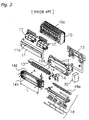
- the indoor unit of the pair type air conditioner comprises a fan rotor 3, a heat exchanger 4, an electrical equipment box 30, and the like. These constituent parts are arranged inside a casing comprising a front surface grille assembly 10, a front surface panel 11, a bottom frame 12, and the like.
- the bottom frame 12 is fixed to an indoor wall and the like by mounting it to a mounting plate 15 fixed to an indoor wall surface.
- An upper inlet 10a having slits is provided in the upper surface of the front surface grille assembly 10, and a front surface inlet 11a is also provided at the top and sides of the front surface panel 11.
- Air cleaning air filters 17 are arranged on the inside of these inlets 10a, 11a.
- an outlet for blowing out the airflow generated by the fan rotor 3 is formed at the front bottom part of the front surface grille assembly 10.
- the fan rotor 3 is arranged in a fan housing part 12a formed in the bottom frame 12, with one end being attached to the bottom frame 12 via a bearing 13, and the other end being coupled to the rotational shaft of a motor 14.
- This motor 14 is fixed to the bottom frame 12 by a motor fixed member 16.
- the heat exchanger 4 is provided so that it surrounds the front, upper, and rear upper parts of the fan rotor 3, and is also split into a front side heat exchanger 141 and a rear side heat exchanger 142, each having an effective length L.
- a front side heat exchanger 141 and a rear side heat exchanger 142 each having an effective length L.
- numerous heat radiating fins are attached to a heat transfer pipe bent a plurality of times at both the left and right ends, the air sucked in from the upper inlet 10a and the front surface inlet 11a by the drive of the fan rotor 3 is made to pass through to the fan rotor 3 side, and heat is exchanged between the air and the refrigerant that passes through the inside of the heat transfer pipe.
- the heat exchanger 4 is connected via the refrigerant piping to the refrigerant piping from the outdoor unit.
- a drain pan assembly 18 that includes a front drain pan, a vane for adjusting the direction of the blown out air, and the like.
- the effective length of a front side heat exchanger and a rear side heat exchanger of a heat exchanger may not necessarily be the same.
- the indoor unit of the above pair type air conditioner as shown in FIG. 1 and FIG. 2, and the indoor unit employed by a multi-split type air conditioner that connects a plurality of indoor units in parallel to one outdoor unit were conventionally designed separately. Given this situation, attempts are recently being made to standardize parts between pair type indoor units and multi-split type indoor units. Although the specifications for the heat exchanger often differ between a pair type and a multi-split type, the standardization of the casing parts and the like is conceivable.
- the indoor unit of a multi-split type air conditioner is often internally provided with a motor operated valve because the plurality of indoor units are separately started and stopped, and controlled.
- This motor operated valve serves the role of adjusting the amount of refrigerant flowing in the heat exchanger of the indoor unit, and generates a relatively loud noise, such as when the refrigerant expands in the liquid-gas mixture state.
- a noise source of the motor operated valve and the like which are parts inherent to the multi-split type indoor unit, is arranged inside a regular pair type casing
- the refrigerant piping bank in the pair type indoor unit is arranged in the space on the side of the centrally disposed heat exchanger.
- the abnormal noise will cease if it is a pair type indoor unit, although it is assumed that abnormal noise from the motor operated valve and the like will leak out into the room if it is a multi-split type indoor unit.
- An indoor unit of an air conditioner according to Claim 1 is an indoor unit of an air conditioner that air-conditions by the condensation and expansion of a refrigerant, comprising a heat exchanger and refrigerant circuit parts.
- the heat exchanger exchanges heat between a refrigerant and air, and comprises a front side heat exchanger and a rear side heat exchanger.
- the rear side heat exchanger has an effective length less than the front side heat exchanger.
- the refrigerant circuit parts change the flow of the refrigerant, and include a motor operated expansion valve, a distributor, and the like.
- the refrigerant circuit parts are arranged in a space created by the difference in the effective lengths of the front side heat exchanger and the rear side heat exchanger.
- the present invention herein is constituted so that the effective length of the rear side heat exchanger is less than the effective length of the front side heat exchanger, and a prescribed space is created on the backside of the indoor unit. Furthermore, refrigerant circuit parts, such as the motor operated valve and the distributor that generate relatively loud sounds when changing the flow of the refrigerant, are arranged in that space. Thus, because the refrigerant circuit parts that constitute noise sources herein are arranged in the space on the backside inside the indoor unit, the amount of sound leaking out to the front side of the indoor unit is reduced, thus suppressing discomfort to people in the room.
- the indoor unit of the air conditioner according to Claim 2 is the indoor unit as recited in Claim 1 that is the indoor unit of an air conditioner comprising an outdoor unit and a plurality of indoor units.
- the refrigerant circuit parts arranged in the space, created because the effective length of the rear side heat exchanger is less than the front side heat exchanger, includes at least a motor-operated valve.
- the motor operated valve is provided for adjusting the amount of refrigerant flowing to the plurality of indoor units.
- the motor operated valve which is usually built into the indoor unit of a multi-split type air conditioner, is arranged in the space on the backside inside the indoor unit, which easily confines noise.
- the motor operated valve sometimes generates a relatively loud abnormal sound when adjusting the amount of refrigerant; however, because it is arranged herein in the abovementioned space, which tends not to leak sound out of the indoor unit, a loud abnormal sound is no longer heard by people in the room.
- the indoor unit of the air conditioner according to Claim 3 is the indoor unit as recited in Claim 1 or Claim 2, further comprising a metal member that covers the space wherein the refrigerant circuit parts are arranged.
- the space is further covered by a metal member. Accordingly, even in a case where a loud abnormal noise generated from the refrigerant circuit parts passes through the casing, which is usually made of resin, and leaks out of the indoor unit, the leakage of that abnormal noise out of the indoor unit can be suppressed by the noise insulating effect of the metal member.
- the indoor unit of the air conditioner according to Claim 4 is the indoor unit of the air conditioner as recited in any one claim of Claim 1 through Claim 3, further comprising a fan rotor and windbreaking members.
- the fan rotor sends air-conditioned air indoors.
- the windbreaking members are arranged between the space, wherein the refrigerant circuit parts are arranged, and the fan rotor.
- the indoor unit is constituted so that the effective length of the rear side heat exchanger is less than the effective length of the front side heat exchanger, then the length of the fan rotor is matched to the front side heat exchanger, whose effective length would normally be thought to be long. Consequently, the abovementioned space (space created by the difference in the effective lengths of the front side heat exchanger and the rear side heat exchanger) is contiguous to a part of the fan rotor. In this case, even if nothing is provided between that space and the fan rotor, there is a risk that air will flow from the abovementioned space directly into the fan rotor without passing through the heat exchanger.
- the indoor unit of the air conditioner according to Claim 5 is the indoor unit as recited in Claim 4, further comprising a drain pan that receives drain water falling from the heat exchanger. Further, the lower ends of the windbreaking members extend to the drain pan. This drain pan is arranged below the lower end of the front side heat exchanger and below the lower end of the rear side heat exchanger, and receives the drain water; it is also widely used in conventional indoor units.
- An indoor unit of an air conditioner according to one embodiment of the present invention is used in a multi-split type air conditioner, as shown in FIG. 3.
- a multi-split type air conditioner 91 a plurality of indoor units 93 - 96 are connected to one outdoor unit 92.
- the outdoor unit 92 and the indoor units 93 - 96 are connected by connecting parts 99a - 99d comprising refrigerant piping and a transmission line.
- Four indoor units 93 - 96 are respectively arranged in separate rooms in, for example, a home, a building, or a store.
- FIG. 4 depicts a refrigerant circuit 190 of the multi-split type air conditioner 91.
- the refrigerant circuit 190 comprises one outdoor unit 92, four indoor units 93 - 96 connected in parallel to the outdoor unit 92, and refrigerant piping.
- the outdoor unit 92 comprises a compressor 20, a four-way switching valve 21, an outdoor heat exchanger 22, an accumulator 23, and the like.
- a discharge pipe thermistor 24 is attached to the discharge side of the compressor 20 for detecting the discharge pipe temperature on the discharge side of the compressor 20.
- the outdoor unit 92 is provided with an outside air thermistor 25 for detecting the outside air temperature, and an outdoor heat exchange thermistor 26 for detecting the temperature of the outdoor heat exchanger 22.
- Each of the indoor units 93 - 96 has the same constitution. The following explains the indoor units 93 - 96 using the indoor unit 93 as an example.
- the indoor unit 93 comprises an indoor heat exchanger 4a and a motor-operated valve (expansion valve) 33a mutually connected in series.
- the motor-operated valve 33a is provided on the refrigerant exit side of the indoor heat exchanger 4a and adjusts the amount of refrigerant flowing to the indoor heat exchanger 4a.
- the indoor unit 93 respectively comprises a room temperature thermistor 31a for detecting the indoor temperature, and an indoor heat exchange thermistor 32a for detecting the temperature of the indoor heat exchanger 4a.
- a liquid pipe thermistor 34a for detecting the liquid pipe temperature between the indoor heat exchanger 4a and the motor-operated valve 33a is provided in the piping between the indoor heat exchanger 4a and the motor-operated valve 33a.
- a gas pipe thermistor 35a is provided on the gas pipe side (refrigerant entrance side) of the indoor heat exchanger 4a for detecting the refrigerant temperature passing therethrough internally.
- the other indoor units 94, 95, 96 are likewise constituted the same as the indoor unit 93, and their indoor heat exchangers, motor operated valves, and various thermistors are assigned equivalent symbols in FIG. 4.
- the indoor units 93 - 96 used in the multi-split type air conditioner 91 have built-in motor-operated valves 33a - 33d.
- the following explains the indoor unit used in the multi-split type air conditioner, using the indoor unit 93 as an example, and focusing on the arrangement of the parts.
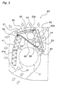
- the indoor heat exchanger 4a that partially covers the front, upper, and rear parts of a fan rotor 3 principally comprises a front side heat exchanger 41 and a rear side heat exchanger 42, as shown in FIG. 5 and FIG. 6.
- the rear side heat exchanger 42 has an effective length that is less than the front side heat exchanger 41, and an end part 42b on a motor 14 side thereof is positioned closer to the central portion in the latitudinal direction of the indoor unit 93 than an end part 41b of the front side heat exchanger 41 (refer to FIG. 5).
- a relatively large space SP is ensured on the outer side of the rear side heat exchanger 42 (the side on the motor 14 side).
- the width dimension of this space SP is substantially the same dimension as the difference in the effective lengths of the front side heat exchanger 41 and the rear side heat exchanger 42, and is 100 - 150 mm.
- a structure is employed in the indoor unit 93 wherein an upper end 41a of the front side heat exchanger 41 is slightly spaced apart from an upper end 42a of the rear side heat exchanger 42, and a connecting plate 43 extends therebetween.
- This connecting plate 43 integrates the front side heat exchanger 41 and the rear side heat exchanger 42 as the indoor heat exchanger 4a, and serves the role of preventing the unfortunate passage of the air from above the indoor heat exchanger 4a to the fan rotor 3 below without passing through the front side heat exchanger 41, the rear side heat exchanger 42, and the like.
- the motor-operated valve 33a in the indoor unit 93, the motor-operated valve 33a, refrigerant piping 133 that connects to the motor-operated valve 33a, and a distributor 39 that divides the flow of refrigerant exiting the motor-operated valve 33a to each of the heat transfer passageways of the indoor heat exchanger 4a, and the like, are arranged in the space SP created by the difference in the effective lengths of the front side heat exchanger 41 and the rear side heat exchanger 42. As shown in FIG. 5, the motor-operated valve 33a is arranged laterally to improve maintainability.
- the space SP is enclosed by a metal cover 50, a vertical partition plate 44, and a lateral partition plate 45.
- the metal cover 50 is a plate member integrally formed from a first cover part 51 that covers the upper part of the space SP, a second cover part 52 that extends downward diagonally from the front end of the first cover part 51 along the front surface of the front side heat exchanger 41, and a third cover part 53 that extends downward diagonally from the rear end of the first cover part 51 and covers the rear of the space SP.
- This metal cover 50 is provided principally for the purpose of isolating noise.
- the vertical partition plate 44 and the lateral partition plate 45 are plate-shaped members made of metal and provided to prevent the leakage of air that flows into the space SP out to the fan rotor side.
- the vertical partition plate 44 is positioned above the fan rotor 3, and partitions the space surrounding the fan rotor 3 and the space SP wherein the motor-operated valve 33a and the like are arranged.
- the lateral partition plate 45 is a substantially triangular member that extends perpendicularly frontward from the end part 42b on the space SP side of the rear side heat exchanger 42, and the sides abut orthogonally with the end part 42b of the rear side heat exchanger 42, the end part on the space SP side of the connecting plate 43, and the end part of the vertical partition plate 44.
- a front drain pan 61 is arranged below the lower end of the front side heat exchanger 41, and a rear drain pan 62 is arranged below the lower end of the rear side heat exchanger 42, respectively.
- These drain pans 61, 62 form a bottom frame and a drain pan assembly having a constitution the same as the conventional bottom frame 12 and drain pan assembly 18 in FIG. 2, and serve the role of receiving the drain water that drips downward from the indoor heat exchanger 4a and the like.
- a drain route 63 is formed below the portion where the abovementioned vertical partition plate 44, the lateral partition plate 45, and the end part 42b on the space SP side of the rear side heat exchanger 42, which surround the space SP, intersect so that the drain water from that portion does not drip down to the fan rotor 3.
- This drain route 63 is structured so that a metal plate is bent at the intersecting portion of the vertical partition plate 44 and the lateral partition plate 45 (a part of the vertical partition plate 44, a part of the lateral partition plate 45, or separate members mounted to these partition plates 44, 45), and so that its cross-section is pocket-shaped.
- the indoor unit 93 is constituted so that the effective length of the rear side heat exchanger 42 is less than the effective length of the front side heat exchanger 41, and a prescribed space SP is created on the rear side of the indoor unit 93. Furthermore, refrigerant circuit parts, such as the motor operated valve 33a and the distributor 39 that generate comparatively loud sounds when changing the flow of the refrigerant, are arranged in that space SP. Thus, because noise sources such as the motor-operated valve 33a can be arranged on the rear side of the indoor unit 93, the noise level that can be heard by people in the room, judging from the directionality of the noise, can be kept low.
- the indoor unit 93 not only is the amount of noise that leaks out to the front side of the indoor unit 93 suppressed by arranging the refrigerant circuit parts that form the noise sources, such as the motor-operated valve 33a, in the space SP on the back side of the indoor unit 93, but the space SP is further covered by a metal cover 50. Accordingly, even in a case where a loud abnormal noise generated by the motor-operated valve 33a and the like passes through the casing, which is usually made of resin, and leaks out of the indoor unit 93, the leakage of that abnormal noise out of the indoor unit 93 will be suppressed by the noise insulating effect of the metal cover 50.
- the indoor unit 93 is constituted so that the effective length of the rear side heat exchanger 42 is less than the effective length of the front side heat exchanger 41, the length of the fan rotor 3 corresponding to the effective length of the front side heat exchanger 41 is greater than the rear side heat exchanger 42. Thereby, the space SP is positioned above a portion of the motor 14 side of the fan rotor 3.
- the vertical partition plate 44 prevents air from flowing down from the space SP to the fan rotor 3
- the lateral partition plate 45 prevents the air from flowing from the space SP to the fan rotor 3 through the space between the front side heat exchanger 41 and the end part 42b of the rear side heat exchanger 42.
- FIG. 6 because the lower ends of the vertical partition plate 44 and the lateral partition plate 45 are positioned above the rear drain pan 62, even when water droplets flow to the partition plates 44, 45 from the end part 42b of the rear side heat exchanger 42 and the like, that water flows into the rear drain pan 62.
- the drain water that exits from the intersecting portion of the end part 42b of the rear side heat exchanger 42, which is shorter than the fan rotor 3, and both partition plates 44, 45 to the fan rotor 3 side via the gap due to the pressure differential and the like is guided to the rear drain pan 62 by the drain route 63. Consequently, the problem of the drain water dripping down to the fan rotor 3 is suppressed even if the space SP is provided as described above and the space SP is enclosed by the partition plates 44, 45.
- the indoor unit 93 comprises the motor-operated valve 33a, and it is difficult to conceive of also using it as is in a pair type air conditioner, such as a room air conditioner. However, it is possible to design a structure so that the indoor heat exchanger 4a of the indoor unit 93 is replaced with an indoor heat exchanger for a pair type air conditioner, thereby standardizing the casing portion for both multi-split types and pair types.
- an indoor heat exchanger is installed wherein the effective lengths of a front side heat exchanger and a rear side heat exchanger differ as in the abovementioned indoor unit 93, and, in a pair type indoor unit, an indoor heat exchanger is installed wherein the effective lengths of the front side heat exchanger and the rear side heat exchanger are the same.
- the heat exchanger unit reduces the amount of noise leaking out to the front side of the indoor unit and suppresses discomfort to people in the room because the effective length of the rear side heat exchanger is less than the effective length of the front side heat exchanger, a prescribed space is created on the back side of the indoor unit, and the refrigerant circuit parts, such as the motor operated valve and the distributor, which generate a relatively loud sound when changing the flow of the refrigerant, are arranged in that space.
Landscapes
- Engineering & Computer Science (AREA)
- Chemical & Material Sciences (AREA)
- Combustion & Propulsion (AREA)
- Mechanical Engineering (AREA)
- General Engineering & Computer Science (AREA)
- Physics & Mathematics (AREA)
- Thermal Sciences (AREA)
- Air Filters, Heat-Exchange Apparatuses, And Housings Of Air-Conditioning Units (AREA)
- Air-Conditioning Room Units, And Self-Contained Units In General (AREA)
- Devices For Blowing Cold Air, Devices For Blowing Warm Air, And Means For Preventing Water Condensation In Air Conditioning Units (AREA)
- Air Conditioning Control Device (AREA)
Abstract
Description
Claims (5)
- An indoor unit of an air conditioner that air-conditions by the condensation and expansion of a refrigerant, comprising:wherein,a heat exchanger (4a) comprising a front side heat exchanger (41) and a rear side heat exchanger (42), and that exchanges heat between a refrigerant and air; andrefrigerant circuit parts (33a, 39) that change the flow of said refrigerant;
said rear side heat exchanger (42) has an effective length less than said front side heat exchanger (41); and
said refrigerant circuit parts (33a, 39) are arranged in a space (SP) created by the difference in the effective lengths of said front side heat exchanger (41) and said rear side heat exchanger (42). - The indoor unit of the air conditioner as recited in Claim 1 that is the indoor unit of an air conditioner (91) comprising an outdoor unit (92) and a plurality of indoor units (93 - 96), wherein
said refrigerant circuit parts arranged in said space (SP) include at least a motor-operated valve (33a) for adjusting the amount of refrigerant flowing to said plurality of indoor units (93 - 96). - The indoor unit of the air conditioner as recited in Claim 1 or Claim 2, further comprising:a metal member (50) that covers said space (SP).
- The indoor unit of the air conditioner as recited in any one claim of Claim 1 through Claim 3, further comprising:a fan rotor (3) for sending air conditioned air indoors; andwindbreaking members (44, 45) arranged between said space (SP) and said fan rotor (3).
- The indoor unit of the air conditioner as recited in Claim 4, further comprising:a drain pan (62) that receives drain water falling from said heat exchanger (4a); wherein,the lower ends of said windbreaking members (44, 45) extend to said drain pan (62).
Applications Claiming Priority (3)
| Application Number | Priority Date | Filing Date | Title |
|---|---|---|---|
| JP2002139745 | 2002-05-15 | ||
| JP2002139745A JP3731067B2 (en) | 2002-05-15 | 2002-05-15 | Air conditioner indoor unit |
| PCT/JP2003/005671 WO2003098119A1 (en) | 2002-05-15 | 2003-05-06 | Indoor unit for air conditioner |
Publications (3)
| Publication Number | Publication Date |
|---|---|
| EP1515095A1 true EP1515095A1 (en) | 2005-03-16 |
| EP1515095A4 EP1515095A4 (en) | 2010-07-14 |
| EP1515095B1 EP1515095B1 (en) | 2011-10-26 |
Family
ID=29544903
Family Applications (1)
| Application Number | Title | Priority Date | Filing Date |
|---|---|---|---|
| EP03721034A Expired - Lifetime EP1515095B1 (en) | 2002-05-15 | 2003-05-06 | Indoor unit for air conditioner |
Country Status (8)
| Country | Link |
|---|---|
| EP (1) | EP1515095B1 (en) |
| JP (1) | JP3731067B2 (en) |
| KR (1) | KR100605844B1 (en) |
| CN (2) | CN1294386C (en) |
| AT (1) | ATE530856T1 (en) |
| AU (1) | AU2003235853B2 (en) |
| ES (1) | ES2373546T3 (en) |
| WO (1) | WO2003098119A1 (en) |
Cited By (3)
| Publication number | Priority date | Publication date | Assignee | Title |
|---|---|---|---|---|
| EP1970638A1 (en) * | 2007-03-15 | 2008-09-17 | Sanyo Electric Co., Ltd. | Air conditioner |
| US20120097747A1 (en) * | 2010-10-25 | 2012-04-26 | Purnell Thomas L | Temperature control system for a controlled environmental vault |
| CN113108419A (en) * | 2021-03-15 | 2021-07-13 | 珠海格力电器股份有限公司 | Control method of multi-split air conditioning system |
Families Citing this family (4)
| Publication number | Priority date | Publication date | Assignee | Title |
|---|---|---|---|---|
| JP2008309444A (en) * | 2007-06-18 | 2008-12-25 | Fujitsu General Ltd | Air conditioner |
| JP6616076B2 (en) * | 2015-02-09 | 2019-12-04 | シャープ株式会社 | Air conditioner |
| JP7244773B2 (en) * | 2021-01-22 | 2023-03-23 | ダイキン工業株式会社 | Wall-mounted air conditioning indoor units and air conditioners |
| CN113432190A (en) * | 2021-07-08 | 2021-09-24 | 宁波奥克斯电气股份有限公司 | Machine and air conditioner in air conditioning |
Family Cites Families (7)
| Publication number | Priority date | Publication date | Assignee | Title |
|---|---|---|---|---|
| JPH07139837A (en) * | 1993-11-12 | 1995-06-02 | Sanyo Electric Co Ltd | Air conditioner |
| JP3121505B2 (en) * | 1994-11-02 | 2001-01-09 | 三菱電機株式会社 | Air conditioner |
| JPH09280597A (en) * | 1996-04-09 | 1997-10-31 | Hitachi Ltd | Wall mounted air conditioner |
| JPH10205877A (en) * | 1997-01-20 | 1998-08-04 | Fujitsu General Ltd | Air conditioner |
| JP3276918B2 (en) * | 1998-02-25 | 2002-04-22 | 三洋電機株式会社 | Air conditioner |
| JP4296649B2 (en) * | 1999-09-13 | 2009-07-15 | ダイキン工業株式会社 | Air conditioner indoor unit |
| JP2001090985A (en) * | 1999-09-27 | 2001-04-03 | Daikin Ind Ltd | Indoor unit of air conditioner |
-
2002
- 2002-05-15 JP JP2002139745A patent/JP3731067B2/en not_active Expired - Fee Related
-
2003
- 2003-05-06 AT AT03721034T patent/ATE530856T1/en not_active IP Right Cessation
- 2003-05-06 KR KR1020047017783A patent/KR100605844B1/en not_active Expired - Fee Related
- 2003-05-06 WO PCT/JP2003/005671 patent/WO2003098119A1/en not_active Ceased
- 2003-05-06 EP EP03721034A patent/EP1515095B1/en not_active Expired - Lifetime
- 2003-05-06 CN CNB038097176A patent/CN1294386C/en not_active Expired - Fee Related
- 2003-05-06 AU AU2003235853A patent/AU2003235853B2/en not_active Ceased
- 2003-05-06 ES ES03721034T patent/ES2373546T3/en not_active Expired - Lifetime
- 2003-05-13 CN CN032575602U patent/CN2723879Y/en not_active Expired - Lifetime
Cited By (5)
| Publication number | Priority date | Publication date | Assignee | Title |
|---|---|---|---|---|
| EP1970638A1 (en) * | 2007-03-15 | 2008-09-17 | Sanyo Electric Co., Ltd. | Air conditioner |
| US20120097747A1 (en) * | 2010-10-25 | 2012-04-26 | Purnell Thomas L | Temperature control system for a controlled environmental vault |
| US9267701B2 (en) * | 2010-10-25 | 2016-02-23 | Thomas L Purnell | Temperature control system for a controlled environmental vault |
| CN113108419A (en) * | 2021-03-15 | 2021-07-13 | 珠海格力电器股份有限公司 | Control method of multi-split air conditioning system |
| CN113108419B (en) * | 2021-03-15 | 2022-06-17 | 珠海格力电器股份有限公司 | Control method of multi-split air conditioning system |
Also Published As
| Publication number | Publication date |
|---|---|
| KR20050007388A (en) | 2005-01-17 |
| EP1515095A4 (en) | 2010-07-14 |
| ES2373546T3 (en) | 2012-02-06 |
| WO2003098119A1 (en) | 2003-11-27 |
| CN2723879Y (en) | 2005-09-07 |
| KR100605844B1 (en) | 2006-08-01 |
| AU2003235853B2 (en) | 2006-07-27 |
| CN1650134A (en) | 2005-08-03 |
| AU2003235853A1 (en) | 2003-12-02 |
| ATE530856T1 (en) | 2011-11-15 |
| JP2003336857A (en) | 2003-11-28 |
| JP3731067B2 (en) | 2006-01-05 |
| EP1515095B1 (en) | 2011-10-26 |
| CN1294386C (en) | 2007-01-10 |
Similar Documents
| Publication | Publication Date | Title |
|---|---|---|
| US8286445B2 (en) | Water-cooled air conditioner | |
| KR100517901B1 (en) | Front suction/discharge type outdoor unit for airconditioner | |
| US6745589B2 (en) | Single-package air conditioner | |
| CN108119963B (en) | Outdoor unit and air conditioner having the same | |
| EP1515095B1 (en) | Indoor unit for air conditioner | |
| KR20050012223A (en) | Front suction/discharge type outdoor unit for air conditioner | |
| JP2014240713A (en) | Outdoor unit for air conditioner | |
| JP2000065376A (en) | Ceiling cassette type air conditioner | |
| JP4109813B2 (en) | Air conditioner outdoor unit | |
| JP2018119714A (en) | Embedded ceiling air conditioner | |
| JP3900004B2 (en) | Air conditioner | |
| JP3257753B2 (en) | Air conditioner | |
| KR20030046365A (en) | Safety operation apparatus and its method for outdoor's unit | |
| KR20050064963A (en) | The supporting structure of pipe for duct type air-conditioner | |
| CN219612444U (en) | Air conditioner external unit and data center air conditioning system | |
| KR20030036581A (en) | Front suction and discharge type outdoor unit for air-conditioner | |
| KR100982857B1 (en) | Front suction and discharge type outdoor unit for air-conditioner | |
| WO2005052457A1 (en) | Air conditioner | |
| KR20030040338A (en) | Front suction and discharge type outdoor unit for air-conditioner | |
| KR200272518Y1 (en) | Blower fixed structure of in door unit for an aricondition | |
| JP2018204827A (en) | Duct type air conditioner | |
| KR200334459Y1 (en) | Fender plate for Air-conditioner filled in ceiling | |
| CN115447339A (en) | Air duct assembly for vehicle-mounted air conditioner and vehicle-mounted air conditioner | |
| KR20030045746A (en) | Front suction and discharge type outdoor unit for air-conditioner and sirocco fan used for it | |
| KR20100091136A (en) | Front suction and discharge type outdoor unit for air-conditioner |
Legal Events
| Date | Code | Title | Description |
|---|---|---|---|
| PUAI | Public reference made under article 153(3) epc to a published international application that has entered the european phase |
Free format text: ORIGINAL CODE: 0009012 |
|
| 17P | Request for examination filed |
Effective date: 20041214 |
|
| AK | Designated contracting states |
Kind code of ref document: A1 Designated state(s): AT BE BG CH CY CZ DE DK EE ES FI FR GB GR HU IE IT LI LU MC NL PT RO SE SI SK TR |
|
| AX | Request for extension of the european patent |
Extension state: AL LT LV MK |
|
| DAX | Request for extension of the european patent (deleted) | ||
| A4 | Supplementary search report drawn up and despatched |
Effective date: 20100610 |
|
| 17Q | First examination report despatched |
Effective date: 20100917 |
|
| GRAP | Despatch of communication of intention to grant a patent |
Free format text: ORIGINAL CODE: EPIDOSNIGR1 |
|
| RIC1 | Information provided on ipc code assigned before grant |
Ipc: F24F 1/00 20110101AFI20110421BHEP |
|
| GRAS | Grant fee paid |
Free format text: ORIGINAL CODE: EPIDOSNIGR3 |
|
| GRAA | (expected) grant |
Free format text: ORIGINAL CODE: 0009210 |
|
| AK | Designated contracting states |
Kind code of ref document: B1 Designated state(s): AT BE BG CH CY CZ DE DK EE ES FI FR GB GR HU IE IT LI LU MC NL PT RO SE SI SK TR |
|
| REG | Reference to a national code |
Ref country code: GB Ref legal event code: FG4D |
|
| REG | Reference to a national code |
Ref country code: CH Ref legal event code: EP |
|
| REG | Reference to a national code |
Ref country code: IE Ref legal event code: FG4D |
|
| REG | Reference to a national code |
Ref country code: DE Ref legal event code: R096 Ref document number: 60338900 Country of ref document: DE Effective date: 20111222 |
|
| REG | Reference to a national code |
Ref country code: ES Ref legal event code: FG2A Ref document number: 2373546 Country of ref document: ES Kind code of ref document: T3 Effective date: 20120206 |
|
| REG | Reference to a national code |
Ref country code: NL Ref legal event code: VDEP Effective date: 20111026 |
|
| REG | Reference to a national code |
Ref country code: AT Ref legal event code: MK05 Ref document number: 530856 Country of ref document: AT Kind code of ref document: T Effective date: 20111026 |
|
| PG25 | Lapsed in a contracting state [announced via postgrant information from national office to epo] |
Ref country code: BE Free format text: LAPSE BECAUSE OF FAILURE TO SUBMIT A TRANSLATION OF THE DESCRIPTION OR TO PAY THE FEE WITHIN THE PRESCRIBED TIME-LIMIT Effective date: 20111026 |
|
| PG25 | Lapsed in a contracting state [announced via postgrant information from national office to epo] |
Ref country code: GR Free format text: LAPSE BECAUSE OF FAILURE TO SUBMIT A TRANSLATION OF THE DESCRIPTION OR TO PAY THE FEE WITHIN THE PRESCRIBED TIME-LIMIT Effective date: 20120127 Ref country code: SE Free format text: LAPSE BECAUSE OF FAILURE TO SUBMIT A TRANSLATION OF THE DESCRIPTION OR TO PAY THE FEE WITHIN THE PRESCRIBED TIME-LIMIT Effective date: 20111026 Ref country code: SI Free format text: LAPSE BECAUSE OF FAILURE TO SUBMIT A TRANSLATION OF THE DESCRIPTION OR TO PAY THE FEE WITHIN THE PRESCRIBED TIME-LIMIT Effective date: 20111026 Ref country code: PT Free format text: LAPSE BECAUSE OF FAILURE TO SUBMIT A TRANSLATION OF THE DESCRIPTION OR TO PAY THE FEE WITHIN THE PRESCRIBED TIME-LIMIT Effective date: 20120227 Ref country code: NL Free format text: LAPSE BECAUSE OF FAILURE TO SUBMIT A TRANSLATION OF THE DESCRIPTION OR TO PAY THE FEE WITHIN THE PRESCRIBED TIME-LIMIT Effective date: 20111026 |
|
| PG25 | Lapsed in a contracting state [announced via postgrant information from national office to epo] |
Ref country code: CY Free format text: LAPSE BECAUSE OF FAILURE TO SUBMIT A TRANSLATION OF THE DESCRIPTION OR TO PAY THE FEE WITHIN THE PRESCRIBED TIME-LIMIT Effective date: 20111026 |
|
| PG25 | Lapsed in a contracting state [announced via postgrant information from national office to epo] |
Ref country code: EE Free format text: LAPSE BECAUSE OF FAILURE TO SUBMIT A TRANSLATION OF THE DESCRIPTION OR TO PAY THE FEE WITHIN THE PRESCRIBED TIME-LIMIT Effective date: 20111026 Ref country code: DK Free format text: LAPSE BECAUSE OF FAILURE TO SUBMIT A TRANSLATION OF THE DESCRIPTION OR TO PAY THE FEE WITHIN THE PRESCRIBED TIME-LIMIT Effective date: 20111026 Ref country code: BG Free format text: LAPSE BECAUSE OF FAILURE TO SUBMIT A TRANSLATION OF THE DESCRIPTION OR TO PAY THE FEE WITHIN THE PRESCRIBED TIME-LIMIT Effective date: 20120126 Ref country code: CZ Free format text: LAPSE BECAUSE OF FAILURE TO SUBMIT A TRANSLATION OF THE DESCRIPTION OR TO PAY THE FEE WITHIN THE PRESCRIBED TIME-LIMIT Effective date: 20111026 Ref country code: SK Free format text: LAPSE BECAUSE OF FAILURE TO SUBMIT A TRANSLATION OF THE DESCRIPTION OR TO PAY THE FEE WITHIN THE PRESCRIBED TIME-LIMIT Effective date: 20111026 |
|
| PG25 | Lapsed in a contracting state [announced via postgrant information from national office to epo] |
Ref country code: RO Free format text: LAPSE BECAUSE OF FAILURE TO SUBMIT A TRANSLATION OF THE DESCRIPTION OR TO PAY THE FEE WITHIN THE PRESCRIBED TIME-LIMIT Effective date: 20111026 |
|
| PLBE | No opposition filed within time limit |
Free format text: ORIGINAL CODE: 0009261 |
|
| STAA | Information on the status of an ep patent application or granted ep patent |
Free format text: STATUS: NO OPPOSITION FILED WITHIN TIME LIMIT |
|
| 26N | No opposition filed |
Effective date: 20120727 |
|
| REG | Reference to a national code |
Ref country code: DE Ref legal event code: R097 Ref document number: 60338900 Country of ref document: DE Effective date: 20120727 |
|
| PG25 | Lapsed in a contracting state [announced via postgrant information from national office to epo] |
Ref country code: MC Free format text: LAPSE BECAUSE OF NON-PAYMENT OF DUE FEES Effective date: 20120531 |
|
| REG | Reference to a national code |
Ref country code: CH Ref legal event code: PL |
|
| PG25 | Lapsed in a contracting state [announced via postgrant information from national office to epo] |
Ref country code: AT Free format text: LAPSE BECAUSE OF FAILURE TO SUBMIT A TRANSLATION OF THE DESCRIPTION OR TO PAY THE FEE WITHIN THE PRESCRIBED TIME-LIMIT Effective date: 20111026 Ref country code: CH Free format text: LAPSE BECAUSE OF NON-PAYMENT OF DUE FEES Effective date: 20120531 Ref country code: LI Free format text: LAPSE BECAUSE OF NON-PAYMENT OF DUE FEES Effective date: 20120531 |
|
| REG | Reference to a national code |
Ref country code: IE Ref legal event code: MM4A |
|
| PG25 | Lapsed in a contracting state [announced via postgrant information from national office to epo] |
Ref country code: IE Free format text: LAPSE BECAUSE OF NON-PAYMENT OF DUE FEES Effective date: 20120506 |
|
| PG25 | Lapsed in a contracting state [announced via postgrant information from national office to epo] |
Ref country code: FI Free format text: LAPSE BECAUSE OF FAILURE TO SUBMIT A TRANSLATION OF THE DESCRIPTION OR TO PAY THE FEE WITHIN THE PRESCRIBED TIME-LIMIT Effective date: 20111026 |
|
| PG25 | Lapsed in a contracting state [announced via postgrant information from national office to epo] |
Ref country code: TR Free format text: LAPSE BECAUSE OF FAILURE TO SUBMIT A TRANSLATION OF THE DESCRIPTION OR TO PAY THE FEE WITHIN THE PRESCRIBED TIME-LIMIT Effective date: 20111026 |
|
| PG25 | Lapsed in a contracting state [announced via postgrant information from national office to epo] |
Ref country code: LU Free format text: LAPSE BECAUSE OF NON-PAYMENT OF DUE FEES Effective date: 20120506 |
|
| PG25 | Lapsed in a contracting state [announced via postgrant information from national office to epo] |
Ref country code: HU Free format text: LAPSE BECAUSE OF FAILURE TO SUBMIT A TRANSLATION OF THE DESCRIPTION OR TO PAY THE FEE WITHIN THE PRESCRIBED TIME-LIMIT Effective date: 20030506 |
|
| REG | Reference to a national code |
Ref country code: FR Ref legal event code: PLFP Year of fee payment: 13 |
|
| REG | Reference to a national code |
Ref country code: FR Ref legal event code: PLFP Year of fee payment: 14 |
|
| REG | Reference to a national code |
Ref country code: FR Ref legal event code: PLFP Year of fee payment: 15 |
|
| REG | Reference to a national code |
Ref country code: FR Ref legal event code: PLFP Year of fee payment: 16 |
|
| PGFP | Annual fee paid to national office [announced via postgrant information from national office to epo] |
Ref country code: GB Payment date: 20180329 Year of fee payment: 16 |
|
| PGFP | Annual fee paid to national office [announced via postgrant information from national office to epo] |
Ref country code: ES Payment date: 20180605 Year of fee payment: 16 Ref country code: DE Payment date: 20180424 Year of fee payment: 16 |
|
| PGFP | Annual fee paid to national office [announced via postgrant information from national office to epo] |
Ref country code: FR Payment date: 20180412 Year of fee payment: 16 Ref country code: IT Payment date: 20180522 Year of fee payment: 16 |
|
| REG | Reference to a national code |
Ref country code: DE Ref legal event code: R119 Ref document number: 60338900 Country of ref document: DE |
|
| GBPC | Gb: european patent ceased through non-payment of renewal fee |
Effective date: 20190506 |
|
| PG25 | Lapsed in a contracting state [announced via postgrant information from national office to epo] |
Ref country code: DE Free format text: LAPSE BECAUSE OF NON-PAYMENT OF DUE FEES Effective date: 20191203 Ref country code: IT Free format text: LAPSE BECAUSE OF NON-PAYMENT OF DUE FEES Effective date: 20190506 Ref country code: GB Free format text: LAPSE BECAUSE OF NON-PAYMENT OF DUE FEES Effective date: 20190506 |
|
| PG25 | Lapsed in a contracting state [announced via postgrant information from national office to epo] |
Ref country code: FR Free format text: LAPSE BECAUSE OF NON-PAYMENT OF DUE FEES Effective date: 20190531 |
|
| REG | Reference to a national code |
Ref country code: ES Ref legal event code: FD2A Effective date: 20200925 |
|
| PG25 | Lapsed in a contracting state [announced via postgrant information from national office to epo] |
Ref country code: ES Free format text: LAPSE BECAUSE OF NON-PAYMENT OF DUE FEES Effective date: 20190507 |