EP1515048A1 - Pulseur - Google Patents
Pulseur Download PDFInfo
- Publication number
- EP1515048A1 EP1515048A1 EP04019385A EP04019385A EP1515048A1 EP 1515048 A1 EP1515048 A1 EP 1515048A1 EP 04019385 A EP04019385 A EP 04019385A EP 04019385 A EP04019385 A EP 04019385A EP 1515048 A1 EP1515048 A1 EP 1515048A1
- Authority
- EP
- European Patent Office
- Prior art keywords
- blower according
- blower
- region
- ring
- deflector ring
- Prior art date
- Legal status (The legal status is an assumption and is not a legal conclusion. Google has not performed a legal analysis and makes no representation as to the accuracy of the status listed.)
- Withdrawn
Links
Images

Classifications
-
- F—MECHANICAL ENGINEERING; LIGHTING; HEATING; WEAPONS; BLASTING
- F04—POSITIVE - DISPLACEMENT MACHINES FOR LIQUIDS; PUMPS FOR LIQUIDS OR ELASTIC FLUIDS
- F04D—NON-POSITIVE-DISPLACEMENT PUMPS
- F04D29/00—Details, component parts, or accessories
- F04D29/08—Sealings
- F04D29/16—Sealings between pressure and suction sides
- F04D29/161—Sealings between pressure and suction sides especially adapted for elastic fluid pumps
- F04D29/162—Sealings between pressure and suction sides especially adapted for elastic fluid pumps of a centrifugal flow wheel
-
- F—MECHANICAL ENGINEERING; LIGHTING; HEATING; WEAPONS; BLASTING
- F04—POSITIVE - DISPLACEMENT MACHINES FOR LIQUIDS; PUMPS FOR LIQUIDS OR ELASTIC FLUIDS
- F04D—NON-POSITIVE-DISPLACEMENT PUMPS
- F04D29/00—Details, component parts, or accessories
- F04D29/40—Casings; Connections of working fluid
- F04D29/42—Casings; Connections of working fluid for radial or helico-centrifugal pumps
- F04D29/4206—Casings; Connections of working fluid for radial or helico-centrifugal pumps especially adapted for elastic fluid pumps
- F04D29/4213—Casings; Connections of working fluid for radial or helico-centrifugal pumps especially adapted for elastic fluid pumps suction ports
Definitions
- the invention relates to a blower for apparatus for ventilation, heating and / or air conditioning
- the invention proposes to work the shape of the ferrule taking into account the compactness requirements of this while reducing air leakage to the functional surfaces of the blower, especially at the blade level.
- the profiled inner region of the ferrule has a convex curvature oriented towards a downstream end of the blades.
- the thickness of the gap is less than 3 mm, preferably between 2 and 3 mm.
- the outer region of the ring deflector has a convex profile facing the outside of the blower and either locally devoid of matter.
- the zones devoid of materials of the Inner and outer zones with convex curvature of the deflector ring are constituted by grooves or non-through orifices.
- the grooves are concentric and regularly spaced apart from each other.
- the orifices are all the same diameter and are evenly distributed in the form of a ring.
- the number of orifices substantially between 1 and 1000.
- the ring deflector is hollow.
- said deflector ring is made by gas injection of plastic material or in two connected parts mechanically between them, for example by thermo-welding.
- the subject of the invention is also a ventilation apparatus, for heating and / or air conditioning for a passenger compartment of a motor vehicle equipped with a blower as defined above.
- FIG. 1 represents, in half-sectional view, a blower 10 a typical ventilation, heating and / or air conditioning system for vehicle interior (not shown).
- This blower 10 comprises a centrifugal turbine 12 mounted at the inside of an outer casing forming a volute 14.
- the turbine 12 is movable in rotation about a central axis XX 'for laterally sucking air into upstream in order to reject it, under pressure downstream, thereby defining the meaning of air circulation in the blower.
- a high pressure zone 10b is defined in volute 14 and a low pressure zone is defined upstream of the turbine 12, outside the volute 14.
- This turbine 12 is provided for this purpose radial blades 16 distributed annularly around the axis XX '.
- a bowl 18, for channeling the upstream air flow to the blades, is mechanically fixed to the turbine 12.
- the bowl 18 has a zone 18a substantially facing an upstream portion 14a of the volute 14.
- a gap 20 is provided between the bowl and this upstream part of the volute, it measures typically less than 3 mm and preferably between 2 and 3 mm so as to make the air boundary layer detachments at this location virtually nil.
- a deflector ring 22 is disposed opposite the bowl 18.
- deflector ring 22 is integral with a downstream portion 14b the volute 14 which forms a ferrule.
- the deflector ring 22 has an inner region 22a with convex curvature oriented towards the radial blades 16, which themselves present a corresponding concave shape 16b matching that of the inner convex region 22a.
- An air gap 25 is arranged between the concave shape 16b of the blades 16 and the convex interior region 22a of the deflector ring.
- the thickness E of this air gap 25 typically measures less than 3 mm and preferably between 2 and 3 mm so as to render almost no leaks by recirculating air from the high pressure zone 10b to the low pressure zone of the blower 10.
- the deflector ring 22 also has a region Outer 22b convex profile directed towards the outside of the blower 10.
- the ring deflector 14 is locally devoid of material, in order to guarantee a good cooling and a good distribution of the plastic avoiding the unnecessary thicknesses during injection molding under pressure deflector ring 14.
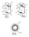
- convex inner region 22a is provided with annular grooves 23a shown in section AA1 in FIG.
- the convex outer region 22b of the deflector ring is provided with annular grooves 23b shown in section AA2 in FIG.
- one or both convex inner and outer regions are provided 23c not circular through holes from one convex region to another.
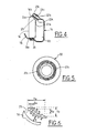
- the distribution of orifices 23c in the form of a ring is illustrated by FIG. 5.
- baffle shown in Figure 7 it is hollow.
- a gas injection process in the material still fluid plastic can be used for this type of embodiment.
- This solution also makes it possible to obtain a substantial gain in material.
- the hollow deflector ring can be made of two parts mechanically linked to one another, for example by thermo-welding, as shown in Figure 8.
- the holes may have shapes, diameters and / or different depths.
- the throats may have, intrinsically or in relation to one another, shapes, widths and / or different depths.
Landscapes
- Engineering & Computer Science (AREA)
- Mechanical Engineering (AREA)
- General Engineering & Computer Science (AREA)
- Structures Of Non-Positive Displacement Pumps (AREA)
Abstract
Description
- une volute, une zone à haute pression d'air étant définie dans la volute et une zone à basse pression d'air étant définie à l'extérieur de la volute,
- une turbine centrifuge montée tournante à l'intérieur de la volute et munie d'une pluralité de pales radiales réparties annulairement,
- un anneau déflecteur faisant partie de la volute pour former une virole, l'anneau déflecteur présentant une région intérieure profilée et une région extérieure, un entrefer étant aménagé entre ladite région intérieure profilée et l'extrémité aval des pales,
- le ratio Rw/Vw entre la largeur des gorges, ou le diamètre des orifices, et la largeur de l'anneau déflecteur est compris entre sensiblement 0,05 et 0,5 ;
- le ratio Rh/Vh entre la profondeur des gorges, ou des orifices, et la hauteur axiale de l'anneau déflecteur est compris entre sensiblement 0,01 et 0,95 ;
- la figure 1, une demi-vue partielle en coupe d'un pulseur conforme à l'invention,
- la figure 2, une demi-vue partielle en coupe d'une variante de réalisation de la figure 1,
- la figure 3, une vue en coupe de la figure 1 selon la ligne AA1 ou de la figure 2 selon la ligne AA2,
- la figure 4, une demi-vue en coupe d'une autre variante de réalisation du pulseur selon l'invention,
- la figure 5, une vue en coupe de la figure 4 selon la ligne AA3 ou AA4,
- la figure 6 une vue de détail de la figure 4,
- la figure 7, une demi-vue en coupe d'une autre variante de réalisation du pulseur selon l'invention, et
- la figure 8, une demi-vue en coupe d'une autre variante de réalisation du pulseur selon l'invention,
Claims (18)
- Pulseur (10) pour appareil de ventilation, de chauffage et/ou de climatisation d'habitacle de véhicule automobile comportant au moins :caractérisé en ce que l'épaisseur (E) de l'entrefer (25) est ajustée pour que les fuites par recirculation d'air de la zone haute pression vers la zone basse pression du pulseur soient sensiblement nulles.une volute (14), une zone à haute pression d'air étant définie dans la volute (14) et une zone à basse pression d'air étant définie à l'extérieur de la volute (14),une turbine centrifuge (12) montée tournante à l'intérieur de la volute (14) et munie d'une pluralité de pales radiales (16) réparties annulairement,un anneau déflecteur (22) faisant partie de la volute (14) pour former une virole, l'anneau déflecteur (22) présentant une région intérieure profilée (22a) et une région extérieure (22b), un entrefer (25) étant aménagé entre ladite région intérieure profilée (22a) et l'extrémité aval (16b) des pales (16),
- Pulseur selon la revendication 1, dans lequel la région intérieure profilée (22a) de la virole présente une courbure convexe orientée vers une extrémité aval (16b) des pales (16).
- Pulseur selon la revendication 1 ou 2, dans lequel l'épaisseur (E) de l'entrefer (25) est inférieure à 3 mm, de préférence comprise entre 2 et 3 mm.
- Pulseur selon l'une quelconque des revendications précédentes dans lequel la région intérieure à courbure convexe (22a) de l'anneau déflecteur (22) est localement dépourvue de matière.
- Pulseur selon la revendication 4, dans lequel les zones dépourvues de matières de la région intérieure à courbure convexe (22a) de l'anneau déflecteur (22) sont constituées par des gorges (23a) non traversantes en direction de la région extérieure (22b).
- Pulseur selon l'une quelconque des revendications précédentes, dans lequel la région extérieure (22b) de l'anneau déflecteur (22) présente un profil convexe orienté vers l'extérieur du pulseur (10).
- Pulseur selon la revendication 6, dans lequel la région extérieure à profil convexe (22b) de l'anneau déflecteur (22) est localement dépourvue de matière.
- Pulseur selon la revendication 7, dans lequel les zones dépourvues de matières de la région extérieure à profil convexe (22b) de l'anneau déflecteur (22) sont constituées par des gorges (23b) non traversantes en direction de la région intérieure (22a).
- Pulseur selon la revendication 5 ou 8, dans lequel les gorges (23a ; 23b) sont concentriques.
- Pulseur selon la revendication 9, dans lequel les gorges (23a ; 23b) sont régulièrement espacées les unes par rapport aux autres.
- Pulseur selon la revendication 4 ou 7, dans lequel la région extérieure et/ou intérieure convexe (22a ; 22b) de l'anneau déflecteur (22) est(sont) munie(s) d'orifices (23c) non débouchant d'une région à l'autre.
- Pulseur selon la revendication 11, dans lequel les orifices (23c) sont tous de même diamètre et sont répartis régulièrement sous forme d'un anneau.
- Pulseur selon l'une quelconque des revendications 5 à 12 dans lequel le ratio RwNw entre la largeur Rw des gorges (23a ; 23b), ou le diamètre des orifices (23c), et la largeur Vw de l'anneau déflecteur (22) est compris entre sensiblement 0,05 et 0,5.
- Pulseur selon l'une quelconque des revendications 5 à 13, dans lequel le ratio RhNh entre la profondeur Rh des gorges (23a ; 23b) , ou des orifices (23c), et la hauteur axiale Vh de l'anneau déflecteur (22) est compris entre sensiblement 0,01 et 0,95.
- Pulseur selon l'une quelconque des revendications 1 à 4, dans lequel l'anneau déflecteur (22) est creux.
- Pulseur selon la revendication 15, dans lequel l'anneau déflecteur (22) est réalisé en injection gaz de matière plastique.
- Pulseur selon la revendication 15, dans lequel l'anneau déflecteur (22) est réalisé en deux parties reliées mécaniquement entre elles, par exemple par thermo-soudage.
- Appareil de ventilation, de chauffage et/ou de climatisation pour habitacle de véhicule automobile comprenant un pulseur (10) selon l'une quelconque des revendications précédentes.
Applications Claiming Priority (2)
| Application Number | Priority Date | Filing Date | Title |
|---|---|---|---|
| FR0310596 | 2003-09-09 | ||
| FR0310596A FR2859508B1 (fr) | 2003-09-09 | 2003-09-09 | Pulseur pour appareil de ventilation, de chauffage et/ou de climatisation d'un habitacle de vehicule |
Publications (1)
| Publication Number | Publication Date |
|---|---|
| EP1515048A1 true EP1515048A1 (fr) | 2005-03-16 |
Family
ID=34130768
Family Applications (1)
| Application Number | Title | Priority Date | Filing Date |
|---|---|---|---|
| EP04019385A Withdrawn EP1515048A1 (fr) | 2003-09-09 | 2004-08-16 | Pulseur |
Country Status (2)
| Country | Link |
|---|---|
| EP (1) | EP1515048A1 (fr) |
| FR (1) | FR2859508B1 (fr) |
Citations (3)
| Publication number | Priority date | Publication date | Assignee | Title |
|---|---|---|---|---|
| DE804394C (de) * | 1949-02-11 | 1951-04-23 | Siemens Schuckertwerke A G | Labyrinthspaltdichtung |
| DE19852895A1 (de) * | 1998-11-17 | 2000-05-18 | Abb Research Ltd | Vorrichtung und Verfahren zur gezielten Unterdrückung mechanischer Schwingungsmoden bei einer Rotationsmaschine |
| DE10004279A1 (de) * | 1999-02-10 | 2000-08-17 | Valeo Climatisation | Heiz- und/oder Klimaanlage mit einem Zentrifugalgebläse |
-
2003
- 2003-09-09 FR FR0310596A patent/FR2859508B1/fr not_active Expired - Fee Related
-
2004
- 2004-08-16 EP EP04019385A patent/EP1515048A1/fr not_active Withdrawn
Patent Citations (3)
| Publication number | Priority date | Publication date | Assignee | Title |
|---|---|---|---|---|
| DE804394C (de) * | 1949-02-11 | 1951-04-23 | Siemens Schuckertwerke A G | Labyrinthspaltdichtung |
| DE19852895A1 (de) * | 1998-11-17 | 2000-05-18 | Abb Research Ltd | Vorrichtung und Verfahren zur gezielten Unterdrückung mechanischer Schwingungsmoden bei einer Rotationsmaschine |
| DE10004279A1 (de) * | 1999-02-10 | 2000-08-17 | Valeo Climatisation | Heiz- und/oder Klimaanlage mit einem Zentrifugalgebläse |
Also Published As
| Publication number | Publication date |
|---|---|
| FR2859508A1 (fr) | 2005-03-11 |
| FR2859508B1 (fr) | 2005-11-11 |
Similar Documents
| Publication | Publication Date | Title |
|---|---|---|
| EP2763892B1 (fr) | Procédé de fabrication d'un panneau d'absorption acoustique | |
| CA2503066C (fr) | Anneau de turbine | |
| FR2966868A1 (fr) | Systeme et procede de refroidissement des zones de plate-forme d'aubes rotatives de turbine | |
| EP1500787A1 (fr) | Dispositif de dégivrage pour aube de roue directrice d'entrée de turbomachine, aube dotée d'un tel dispositif de dégivrage, et moteur d'aéronef equipé de telles aubes | |
| FR2885645A1 (fr) | Aube creuse de rotor pour la turbine d'un moteur a turbine a gaz, equipee d'une baignoire | |
| FR2560287A1 (fr) | Tuyere de stator et moteur a turbine | |
| EP2058473B1 (fr) | Aube métallique fabriquée par moulage | |
| WO2016116686A1 (fr) | Dispositif d'étanchéité entre un système d'injection et un nez d'injecteur de carburant de turbomachine d'aéronef | |
| WO2015155043A1 (fr) | Moteur electrique, dispositif de pulsion d'air et systeme de ventilation de chauffage et/ou de climatisation equipes d'un tel moteur | |
| FR3063776A1 (fr) | Agencement de palier pour un arbre d'entrainement d'une turbomachine, et une turbomachine comportant un tel agencement de palier | |
| FR3119656A1 (fr) | Distributeur hydraulique rotatif a fabrication simplifiée | |
| EP2870011A1 (fr) | Climatiseur, notamment pour véhicule automobile | |
| FR2913479A1 (fr) | Joint tournant et rotor correspondant pour appareil a helices entrainees par l'ejection de gaz sous pression sur une pale et de l'helice, notamment pour helicoptere. | |
| FR2859508A1 (fr) | Pulseur pour appareil de ventilation, de chauffage et/ou de climatisation d'un habitacle de vehicule | |
| FR2859251A1 (fr) | Pulseur a haut rendement aeraulique pour appareil de ventilation, de chauffage et/ou de climatisation d'habitacle de vehicule automobile | |
| WO2013060963A1 (fr) | Vanne, notamment pour moteur de véhicule automobile | |
| EP3447271B1 (fr) | Système de chauffage pour tuyère secondaire convergente-divergente | |
| FR3063777A1 (fr) | Agencement de rouet a double etage pour un turbocompresseur centrifuge a double etage | |
| WO2021058908A1 (fr) | Dispositif de refroidissement par jets d'air d'un carter de turbine | |
| FR3074837B1 (fr) | Aube de rotor pour une turbomachine | |
| FR2739897A1 (fr) | Diffuseur annulaire de recyclage de gaz carbures, pour moteur a combustion interne | |
| CA3099889A1 (fr) | Dispositif de refroidissement d'un carter de turbomachine | |
| EP3935273B1 (fr) | Turbine à gaz contrarotative pour aéronef à double rotor | |
| FR2954419A1 (fr) | Helice de ventilateur et buse de ventilateur associee, en particulier pour vehicule automobile | |
| WO2025078769A1 (fr) | Distributeur hydraulique rotatif avec organe de guidage de fluide |
Legal Events
| Date | Code | Title | Description |
|---|---|---|---|
| PUAI | Public reference made under article 153(3) epc to a published international application that has entered the european phase |
Free format text: ORIGINAL CODE: 0009012 |
|
| AK | Designated contracting states |
Kind code of ref document: A1 Designated state(s): AT BE BG CH CY CZ DE DK EE ES FI FR GB GR HU IE IT LI LU MC NL PL PT RO SE SI SK TR |
|
| AX | Request for extension of the european patent |
Extension state: AL HR LT LV MK |
|
| RAP1 | Party data changed (applicant data changed or rights of an application transferred) |
Owner name: VALEO SYSTEMES THERMIQUES |
|
| 17P | Request for examination filed |
Effective date: 20050824 |
|
| AKX | Designation fees paid |
Designated state(s): AT BE BG CH CY CZ DE DK EE ES FI FR GB GR HU IE IT LI LU MC NL PL PT RO SE SI SK TR |
|
| STAA | Information on the status of an ep patent application or granted ep patent |
Free format text: STATUS: THE APPLICATION IS DEEMED TO BE WITHDRAWN |
|
| 18D | Application deemed to be withdrawn |
Effective date: 20070301 |