EP1514763A1 - Steering column module having a single displacement sensor - Google Patents
Steering column module having a single displacement sensor Download PDFInfo
- Publication number
- EP1514763A1 EP1514763A1 EP04292134A EP04292134A EP1514763A1 EP 1514763 A1 EP1514763 A1 EP 1514763A1 EP 04292134 A EP04292134 A EP 04292134A EP 04292134 A EP04292134 A EP 04292134A EP 1514763 A1 EP1514763 A1 EP 1514763A1
- Authority
- EP
- European Patent Office
- Prior art keywords
- steering column
- module
- axial
- adjustment
- motor
- Prior art date
- Legal status (The legal status is an assumption and is not a legal conclusion. Google has not performed a legal analysis and makes no representation as to the accuracy of the status listed.)
- Granted
Links
- 238000006073 displacement reaction Methods 0.000 title claims description 16
- 230000007246 mechanism Effects 0.000 claims description 11
- 238000013519 translation Methods 0.000 claims description 9
- 230000005540 biological transmission Effects 0.000 claims description 8
- 230000004913 activation Effects 0.000 claims description 5
- 230000005291 magnetic effect Effects 0.000 claims description 4
- 230000003287 optical effect Effects 0.000 claims description 4
- 230000006870 function Effects 0.000 claims description 3
- 230000001939 inductive effect Effects 0.000 claims description 3
- 230000005355 Hall effect Effects 0.000 claims 1
- 235000021183 entrée Nutrition 0.000 description 8
- 238000012986 modification Methods 0.000 description 3
- 230000004048 modification Effects 0.000 description 3
- 238000005259 measurement Methods 0.000 description 2
- 239000000523 sample Substances 0.000 description 2
- 238000012549 training Methods 0.000 description 2
- 101100218353 Talaromyces purpureogenus axeA gene Proteins 0.000 description 1
- 230000008901 benefit Effects 0.000 description 1
- 125000004122 cyclic group Chemical group 0.000 description 1
- 230000003247 decreasing effect Effects 0.000 description 1
- 238000013461 design Methods 0.000 description 1
- 230000000694 effects Effects 0.000 description 1
- 238000002513 implantation Methods 0.000 description 1
- 238000004519 manufacturing process Methods 0.000 description 1
- 238000012545 processing Methods 0.000 description 1
- 125000006850 spacer group Chemical group 0.000 description 1
Images


Classifications
-
- B—PERFORMING OPERATIONS; TRANSPORTING
- B62—LAND VEHICLES FOR TRAVELLING OTHERWISE THAN ON RAILS
- B62D—MOTOR VEHICLES; TRAILERS
- B62D1/00—Steering controls, i.e. means for initiating a change of direction of the vehicle
- B62D1/02—Steering controls, i.e. means for initiating a change of direction of the vehicle vehicle-mounted
- B62D1/16—Steering columns
- B62D1/18—Steering columns yieldable or adjustable, e.g. tiltable
- B62D1/181—Steering columns yieldable or adjustable, e.g. tiltable with power actuated adjustment, e.g. with position memory
Abstract
Description
La présente invention concerne le domaine des colonnes de direction destinées à des véhicules automobiles, et plus particulièrement des modules comprenant une colonne de direction et des moyens motorisés pour la commande de l'inclinaison et de la profondeur du volant. Une colonne de direction à réglage électrique permet le réglage de la position du volant selon deux axes :
- le réglage axial pour rapprocher ou en éloigner le volant du conducteur.
- le réglage radial pour régler la position du volant de haut en bas, ou, notamment pour les véhicules destinés au marché américain, pour régler l'inclinaison du volant entre une position plutôt horizontale et une position plutôt verticale.
- the axial adjustment to move the steering wheel away from or away from the driver.
- the radial adjustment to adjust the position of the steering wheel from top to bottom, or, especially for vehicles for the US market, to adjust the tilt of the steering wheel between a rather horizontal position and a rather vertical position.
Il est connu dans l'état de la technique de réduire le poids et le coût de tels modules par l'utilisation d'un moteur unique assurant à la fois le réglage axial et le réglage longitudinal. Un ou plusieurs mécanismes embrayables assurent la transmission entre un ou plusieurs axes de sortie du moteur unique, pour activer ou désactiver l'entraínement des parties mobiles assurant l'orientation du volant.It is known in the state of the art of reduce the weight and cost of such modules by the use of a single engine ensuring both the axial adjustment and longitudinal adjustment. One or more Engaging mechanisms ensure transmission between one or several single motor output axes, to activate or deactivate the drive of the moving parts ensuring the orientation of the steering wheel.
Le brevet DE10144476A1 concerne une unité de colonne de direction de véhicule automobile comprenant une colonne de direction de longueur et/ou inclinaison réglable par voie électromécanique. L'invention a pour objet de concevoir une unité de ce type qui peut être facilement adaptée à différents types de véhicules, qui peut être reconfigurée de manière variable vis-à-vis de sa fonctionnalité, dès le processus de fabrication, et qui est clairement délimitée des autres unités structurelles du véhicule automobile. A cet effet, l'unité de colonne de direction de véhicule automobile de l'invention comprend, en plus des éléments mécaniques et organes de réglage, nécessaires à la commande de direction et à la modification électrique de la position de la colonne de direction, au moins un système d'entraínement, une unité de commande électronique pour produire des signaux de commande destinés au(x) système(s) d'entraínement et aux organes électriques de réglage, ainsi que des connexions destinées à relier l'unité au réseau de bord.Patent DE10144476A1 relates to a unit of steering column of a motor vehicle comprising a steering column with adjustable length and / or tilt electromechanically. The object of the invention is to design a unit of this type that can be easily adapted to different types of vehicles, which can be reconfigured in a variable way vis-à-vis its functionality, right from the manufacturing process, and that is clearly delineated from the other structural units of the motor vehicle. For this purpose, the column unit of motor vehicle steering of the invention comprises, in addition to the mechanical elements and adjustment members, necessary for steering control and modification electrical position of the steering column, at less a drive system, a control unit to produce control signals for to the drive system (s) and electrical components of adjustment, as well as connections intended to connect the unit to the onboard network.
A titre d'exemple, le brevet allemand DE19641152 décrit une unité de colonne de direction pour véhicule automobile comportant un boítier de colonne de direction et un dispositif de réglage actionné électriquement, servant à réaliser le réglage longitudinal et le réglage d'inclinaison de la colonne de direction. Le dispositif de réglage porte une unité d'entraínement électrique pour entraíner en rotation une broche de réglage et pour déplacer longitudinalement et incliner au moins respectivement un mécanisme de réglage. Pour chaque direction de déplacement, un dispositif de commutation assure l'embrayage ou le débrayage d'un écrou de broche disposé au voisinage de ce dispositif.For example, the German patent DE19641152 discloses a steering column unit for motor vehicle comprising a column housing of direction and an actuating device electrically, used to perform the longitudinal adjustment and tilt adjustment of the steering column. The adjusting device carries a drive unit electrical to rotate a setting pin and to move longitudinally and tilt at least respectively a setting mechanism. For each direction of movement, a switching device ensures the clutching or disengagement of a spindle nut arranged in the vicinity of this device.
Le brevet européen EP0461025 décrit un dispositif motorisé de commande de réglage de la position d'une colonne de direction réglable en profondeur et inclinaison où la colonne de direction comprend un arbre fait d'un tronçon d'extrémité destiné à porter un volant et d'un tronçon intercalaire extensible ou rétractable constitué de deux parties assemblées par une jonction coulissante, des cardans de liaison réunissant ces tronçons. Ce dispositif de l'art antérieur comprend un corps fixe relié au véhicule et un corps mobile constitué d'un élément coulissant relativement au corps fixe et d'un élément basculant relativement à l'élément coulissant à l'aide d'une articulation d'axe (Y) orthogonal à l'axe (X) de la colonne, ainsi que des paliers supportant l'arbre dans le corps mobile. Une transmission associée à un moteur unique présente une entrée reliée au moteur et deux sorties de manière que l'une des sorties provoque la translation et l'autre sortie provoque l'inclinaison. Les deux sorties sont activées à des vitesses relatives appairées pour assurer le réglage en profondeur des deux éléments du corps mobile et des tronçons d'arbre qu'ils portent. Une seule des sorties est activée pour assurer le réglage en inclinaison de l'élément basculant et du tronçon d'arbre qu'il porte. Le corps fixe et le corps mobile constituent une gaine, le corps mobile coulissant dans le corps fixe dans le sens axial.European Patent EP0461025 discloses a motorized position adjustment control device a steering column adjustable in depth and tilt where the steering column includes a tree made of an end section intended to carry a steering wheel and an expandable or retractable spacer consisting of two parts assembled by a junction sliding gimbals, connecting gimbals sections. This device of the prior art comprises a fixed body connected to the vehicle and a movable body constituted sliding element relative to the fixed body and a tilting element relative to the sliding element using an articulation of axis (Y) orthogonal to the axis (X) of the column, as well as bearings supporting the shaft in the moving body. A transmission associated with an engine single has an input connected to the motor and two outputs so that one of the outputs causes the translation and the other output causes inclination. Both outputs are activated at related relative speeds for ensure the depth adjustment of the two body elements mobile and tree sections they carry. Only one outputs is activated to ensure the setting in Tilting tilting element and shaft section he wears. The fixed body and the mobile body constitute a sheath, the mobile body sliding in the fixed body in the axial direction.
Ces différents documents de l'art antérieur proposent des solutions au problème de la motorisation par un moteur unique des réglages de la colonne de direction. Pour qu'un tel module soit pleinement utilisable, il est souhaitable de pouvoir mémoriser une position axiale et longitudinale convenant à un conducteur du véhicule, et de pouvoir restituer cette position lorsque ce conducteur le souhaite.These different documents of the prior art propose solutions to the problem of motorization by a unique engine steering column settings. For such a module to be fully usable, it is desirable to be able to memorize an axial position and longitudinal axis suitable for a driver of the vehicle, and to be able to restore that position when that driver wish.
A cet effet le brevet PCT W003022657 de la société NACAM GmbH propose une unité de colonne de direction comprenant en plus des éléments mécaniques et organes de réglage, nécessaires à la commande de direction et à la modification électrique de la position de la colonne de direction, au moins un système d'entraínement, une unité de commande électronique pour produire des signaux de commande destinés au(x) système(s) d'entraínement et aux organes électriques de réglage, ainsi que des connexions destinées à relier l'unité au réseau de bord. For this purpose the PCT patent W003022657 of the NACAM GmbH offers a column unit of direction further comprising mechanical elements and adjusting elements, necessary for steering control and the electrical modification of the position of the steering column, at least one drive system, an electronic control unit to produce control signals for the system (s) drive and to the electrical control devices, as well as connections to connect the unit to the network of edge.
Cette solution implique une électronique de commande coûteuse, et met en oeuvre des capteurs de position qu'il convient d'intégrer dans les mécanismes respectifs de réglages longitudinal et axial.This solution involves an electronics of expensive control, and implements position sensors should be included in the respective mechanisms of longitudinal and axial adjustments.
On connaít encore le brevet allemand DE3311229 décrivant un dispositif de réglage utilisant un moteur pas à pas de type « brushless » commandé par des trains d'impulsions. Une telle solution n'est pas satisfaisante car en cas de déréglage mécanique du mécanisme d'entraínement, par exemple en raison de l'usure ou d'un dépassement de fin de course, la commande de positionnement est erronée.We still know the German patent DE3311229 describing a setting device using a motor not step by step brushless type controlled by trains pulse. Such a solution is not satisfactory because in the event of mechanical maladjustment of the mechanism of training, for example due to wear or limit overrun, positioning control is wrong.
Le but de la présente invention est de proposer une solution simplifiée d'acquisition des réglages et de commande de la mémorisation et de la restitution d'un réglage sélectionné par un conducteur.The purpose of the present invention is to propose a simplified solution for acquiring settings and control of the memorization and the restitution of a setting selected by a driver.
A cet effet, l'invention concerne selon son acception la plus générale un module de colonne de direction à commande de positionnement motorisée comportant un moteur unique de réglage de la position du volant selon un axe de pivotement transversal pour le réglage de l'inclinaison du volant d'une part, et selon un axe longitudinal pour le réglage de la profondeur d'autre part, ledit moteur entraínant le déplacement d'un premier élément de jonction fileté assurant un premier mécanisme de réglage selon l'un desdits axes, et d'un deuxième élément de jonction fileté entraínant un second mécanisme de réglage selon au moins l'autre desdits axe, ledit module comportant un contrôleur pour la mémorisation d'au moins une position de référence selon lesdits deux axes et pour la comparaison entre une position de référence et la position effective selon lesdits deux axes, caractérisé en ce que ledit moteur unique entraíne un capteur de position incrémental unique délivrant un signal de position audit contrôleur et en ce que ledit contrôleur reçoit en outre une information représentative de l'état de l'un au moins desdits éléments de jonction.For this purpose, the invention relates to most general meaning a column module of direction with motorized positioning control comprising a single motor for adjusting the steering wheel position a transverse pivot axis for the adjustment of the inclination of the steering wheel on the one hand, and along an axis longitudinal for the depth adjustment on the other hand, said motor causing the displacement of a first element threaded connection providing a first adjustment mechanism according to one of said axes, and a second element of threaded connection resulting in a second adjustment mechanism according to at least the other of said axis, said module comprising a controller for storing at least one position of reference along said two axes and for the comparison between a reference position and the actual position along said two axes, characterized in that said engine single drives a single incremental position sensor delivering a position signal to said controller and thereby that said controller receives further information representative of the state of at least one of said elements junction.
Ce capteur incrémental unique peut être soit directement sur le moteur, soit sur un élément quelconque de la transmission, soit même sur l'axe de sortie.This unique incremental sensor can be either directly on the engine, either on any element of the transmission, even on the output axis.
Cet état pourra être "embrayé" ou "débrayé" lorsque l'élément de jonction comporte un embrayage, ou "actif" ou "inactif" lorsqu'il s'agit d'un moteur à deux axes de sortie dont l'un ou l'autre est entraíné. L'information relative à l'état des éléments de jonction vient du circuit de commande qui contrôle le fonctionnement du mécanisme de réglage.This state can be "engaged" or "disengaged" when the joining element comprises a clutch, or "active" or "inactive" in the case of a two-engine output axes of which one or the other is driven. Information on the condition of the connecting elements comes from the control circuit that controls the operation of the adjustment mechanism.
L'avantage de ce système est de n'avoir qu'un seul capteur relatif nécessaire pour toutes les fonctions de positionnement de la colonne selon les deux axes. Ce capteur est en outre facilement intégrable dans le moteur ou sur un élément de la transmission qui actionne le réglage, diminuant ainsi le nombre de composants nécessaires sur la colonne et simplifiant aussi le câblage nécessaire.The advantage of this system is to have only one only relative sensor needed for all functions positioning the column along the two axes. This sensor is also easily integrated in the motor or on an element of the transmission that drives the setting, thus decreasing the number of components needed on the column and also simplifying the wiring necessary.
Selon une première variante, l'un des éléments de jonction entraíne le déplacement axial en translation de la colonne de direction par rapport à la partie fixe du module, et l'autre élément de jonction entraíne la rotation de la colonne de direction par rapport à un axe de pivotement transversal de la colonne de direction par rapport à la partie fixe du module, chacun desdits éléments de jonction coopérant avec une vis filetée unique entraínée par ledit moteur unique, le module comportant des moyens de commande de l'embrayage de l'un au moins des éléments de jonction avec ladite vis filetée, lesdits moyens de commande délivrant ladite information d'activation correspondant à l'état desdits embrayages.According to a first variant, one of the elements junction causes the axial displacement in translation of the steering column with respect to the fixed part of the module, and the other connecting element causes the rotation of the steering column with respect to an axis of transverse pivoting of the steering column by relative to the fixed part of the module, each of those elements junction cooperating with a single threaded screw driven by said single engine, the module comprising means for control of the clutch of at least one of the elements of junction with said threaded screw, said means for command delivering said activation information corresponding to the state of said clutches.
Selon une deuxième variante, l'un des éléments de jonction est en prise permanente avec ladite vis entraínée par le moteur unique. Le contrôleur comporte un premier registre de mémoire incrémenté en fonction des variations du capteur incrémental seulement lorsque l'embrayage du premier moyen de jonction est activé, et un deuxième registre de mémoire incrémenté en fonction des variations dudit capteur incrémental en permanence.According to a second variant, one of the elements junction is in permanent engagement with said screw driven by the single engine. The controller has a first memory register incremented according to the incremental sensor variations only when the clutch of the first joining means is activated, and a second memory register incremented according to the variations of said incremental sensor permanently.
Selon un mode de réalisation adapté pour commander principalement l'inclinaison du volant, ledit pivot est situé du côté de la colonne de direction et de la partie fixe la plus proche du volant.According to an embodiment adapted for mainly control the inclination of the steering wheel, said pivot is located on the side of the steering column and the fixed part closest to the steering wheel.
Selon un mode de réalisation adapté pour commander principalement la hauteur du volant, ledit pivot est situé du côté de la colonne de direction et de la partie fixe la plus éloignée du volant.According to an embodiment adapted for mainly controlling the height of the steering wheel, said pivot is located on the side of the steering column and the fixed part farthest from the steering wheel.
Quelle que soit la variante susvisée, le module comporte avantageusement des détecteurs de la position des éléments de jonction par rapport à une position de référence, délivrant un signal de réinitialisation desdits registres de mémoire. Ces détecteurs peuvent être par exemple des micro-switchs, un détecteur optique, magnétique, inductif ou capacitif, etc...Whatever the variant referred to above, the module advantageously comprises detectors of the position of the junction elements with respect to a position of reference, delivering a reset signal of said memory registers. These detectors can be example of micro-switches, an optical detector, magnetic, inductive or capacitive, etc.
Selon une variante, chacun des éléments de jonction est couplé par l'intermédiaire d'un embrayage avec ladite vis entraínée par le moteur unique et en ce que le contrôleur comporte un premier registre de mémoire incrémenté en fonction des variations du capteur incrémental lorsque l'embrayage du premier moyen de jonction est activé, et un deuxième registre de mémoire incrémenté en fonction des variations dudit capteur incrémental lorsque l'embrayage du deuxième moyen de jonction est activé.According to a variant, each of the elements of junction is coupled via a clutch with said screw driven by the single motor and in that the controller has a first memory register incremented according to sensor variations incremental when the clutch of the first means of junction is activated, and a second memory register incremented according to the variations of said sensor incremental when the clutch of the second means of junction is enabled.
Selon une autre variante, le module comporte des détecteurs de la position des éléments de jonction par rapport à une position de référence, chacun desdits capteurs délivrant un signal de réinitialisation de l'un desdits registres de mémoire.According to another variant, the module comprises detectors of the position of the connecting elements by referred to a reference position, each of those sensors delivering a reset signal of one said memory registers.
Selon un mode de réalisation particulier, le moteur unique comporte deux axes de sorties et un moyen de commutation assurant la sélection de l'une ou de l'autre des dits axes ou des deux axes simultanément.According to a particular embodiment, the single engine has two output axes and a means of switching ensuring the selection of one or the other said axes or both axes simultaneously.
L'un des éléments de jonction coopère par une liaison vis-écrou avec l'un des axes de sortie pour entraíner le déplacement axial en translation de la colonne de direction par rapport à la partie fixe du module, et l'autre des éléments de jonction coopérant par une liaison vis-écrou avec l'autre axe de sortie pour entraíner la rotation de la colonne de direction par rapport à un axe de pivotement transversal de la colonne de direction par rapport à la partie fixe du module, le module comportant des moyens de commutation délivrant ladite information d'activation correspondant à l'état desdits axes de sortie.One of the connecting elements cooperates with a screw-nut connection with one of the output pins for to cause the axial displacement in translation of the column direction relative to the fixed part of the module, and the other of the connecting elements cooperating by a connection screw-nut with the other output shaft to drive the rotation of the steering column with respect to an axis of transverse pivoting of the steering column by relative to the fixed part of the module, the module comprising switching means delivering said information activation corresponding to the state of said output axes.
L'invention concerne également un contrôleur pour un module conforme à l'une au moins des revendications précédentes caractérisé en ce qu'il comporte un premier registre incrémenté par les impulsions délivrées par ledit capteur incrémental entraíné par le moteur unique lorsqu'un réglage axial est sélectionné, et un deuxième registre incrémenté par les impulsions délivrées par ledit capteur incrémental entraíné par le moteur unique lorsqu'un réglage en inclinaison est sélectionné.The invention also relates to a controller for a module according to at least one of the claims preceding characterized in that it comprises a first register incremented by the pulses delivered by said incremental sensor driven by the single motor when axial adjustment is selected, and a second register incremented by the pulses delivered by said sensor incremental driven by the single motor when a setting tilt is selected.
Avantageusement le premier registre est réinitialisé par un signal délivré par un premier détecteur lorsque l'élément de jonction axial est dans une position de référence, et un deuxième registre est réinitialisé par un signal délivré par un deuxième détecteur lorsque l'élément de jonction radial est dans une position de référence.Advantageously, the first register is reset by a signal delivered by a first detector when the axial joining element is in a position reference, and a second register is reset by a signal delivered by a second detector when the radial joining element is in a position of reference.
Selon une variante, le contrôleur comporte un premier registre incrémenté par les impulsions délivrées par ledit capteur incrémental entraíné par le moteur unique lorsqu'un réglage selon l'un des modes de réglage est sélectionné, et un deuxième registre incrémenté par les impulsions délivrées par ledit capteur incrémental entraíné par le moteur unique.According to one variant, the controller comprises a first register incremented by the pulses delivered by said incremental sensor driven by the single motor when a setting according to one of the adjustment modes is selected, and a second register incremented by pulses delivered by said incremental sensor driven by the single engine.
Avantageusement, lesdits registres sont réinitialisés par deux signaux délivrés par des détecteurs lorsque les deux éléments de jonction sont chacun en position de référence. Ces détecteurs peuvent être par exemple des micro-switchs, un détecteur optique, magnétique, inductif ou capacitif, etc...Advantageously, said registers are reset by two signals delivered by detectors when the two connecting elements are each in reference position. These detectors can be example of micro-switches, an optical detector, magnetic, inductive or capacitive, etc.
L'invention sera mieux comprise à la lecture de
la description qui suit, se référant aux dessins annexés
correspondant à des exemples non limitatifs de réalisation,
où :
L'invention peut être mise en oeuvre sous différentes formes de réalisation, ayant comme caractéristique commune de motorisation par un moteur unique, avec un capteur incrémental unique sur le moteur ou un élément de la transmission. Le contrôle du réglage de position d'une colonne monomoteur fait appel à un seul capteur relatif cyclique par exemple une sonde à effet Hall, ou un capteur optique ou magnétique qui délivre une information de rotation du moteur qui entraíne la ou les vis de sortie sur laquelle ou lesquelles se déplacent les jonctions qui assurent le réglage axial ou angulaire.The invention can be implemented under different forms of common characteristic of motorization by an engine unique, with a single incremental sensor on the engine or an element of the transmission. The control of the setting of position of a single-engine column uses only one relative cyclic sensor for example an effect probe Hall, or an optical or magnetic sensor that delivers a information of rotation of the engine which drives the exit screw on which or which move the junctions that provide axial or angular adjustment.
Selon la transmission connectée au moteur et l'implantation du capteur relatif dans le système, le nombre de cycles donnés par ce capteur par tour moteur est variable d'une colonne à l'autre, et ce rapport de transmission doit être pris en compte dans la description ci-dessous.According to the transmission connected to the motor and the implantation of the relative sensor in the system, the number of cycles given by this sensor per motor revolution is variable from one column to another, and this report from transmission must be taken into account in the description below.
Le contrôleur comporte un système de comptage (C) des impulsions délivrées par ce capteur. Ces impulsions sont comptées dans un sens de rotation du moteur, décomptées dans l'autre sens de rotation. Selon l'axe de réglage sélectionné, ces impulsions sont à considérer soit pour la mesure de déplacement axial, soit pour la mesure de déplacement radial. The controller has a counting system (C) pulses delivered by this sensor. These impulses are counted in a direction of rotation of the motor, counted in the other direction of rotation. According to the axis of selected setting, these pulses are to be considered either for the measurement of axial displacement, ie for the measurement of radial displacement.
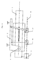
La figure 1 représente une vue schématique d'un exemple de module comportant des réglages axial et radial indépendants, avec un moteur et deux embrayages.FIG. 1 represents a schematic view of a example module with axial and radial settings independent, with one motor and two clutches.
Le module décrit en référence à la figure 1 comporte une colonne de direction (1) mobile selon deux axes par rapport à une partie fixe (2) destinée à assurer la liaison du module avec l'habitacle du véhicule automobile.The module described with reference to FIG. has a steering column (1) movable in two axes with respect to a fixed part (2) intended to ensure the connection of the module with the passenger compartment of the vehicle automobile.
La colonne de direction (1) est mobile en translation par rapport à un fourreau (3) solidaire de la partie fixe (2). Ce fourreau (3) est mobile en rotation autour d'un axe transversal (4) perpendiculaire au plan vertical passant par l'axe de la colonne de direction (1). Cet axe (4) est disposé du côté opposé à l'extrémité de la colonne sur laquelle est monté le volant. Le basculement du fourreau (3) par rapport à cet axe (4) assure le réglage en hauteur du volant, et une légère modification de l'inclinaison du volant.The steering column (1) is movable in translation with respect to a sleeve (3) integral with the fixed part (2). This sheath (3) is rotatable around a transverse axis (4) perpendicular to the plane vertical passing through the axis of the steering column (1). This axis (4) is arranged on the opposite side to the end of the column on which is mounted the steering wheel. The switchover sleeve (3) with respect to this axis (4) ensures the adjustment in height of the steering wheel, and a slight modification of the tilt of the steering wheel.
Le module comporte un moteur unique (5) entraínant une vis sans fin (6) parallèle à l'axe longitudinal de la colonne de direction (1).The module has a single motor (5) driving a worm (6) parallel to the axis longitudinal direction of the steering column (1).
Sur cette vis sans fin (6) sont montés deux éléments de jonction (7, 8).On this worm (6) are mounted two joining elements (7, 8).
Le premier élément de jonction (7) assure le mouvement de basculement du fourreau (3) par rapport à la partie fixe (2). Il comprend à cet effet une bielle (9) dont une extrémité est articulée sur l'élément de jonction (7) et l'autre extrémité est articulée par rapport à un axe de liaison avec la partie fixe (2).The first joining element (7) ensures the tilting movement of the sheath (3) relative to the fixed part (2). It includes for this purpose a connecting rod (9) one end of which is articulated on the joining element (7) and the other end is articulated with respect to an axis connecting with the fixed part (2).
Le déplacement du premier élément de jonction (7) le long de la vis sans fin (6) modifie l'angle formé par cette bielle (9) avec l'axe longitudinal, et donc l'écartement transversal du point de liaison (10) avec l'axe de la colonne de direction (1), et par conséquent l'angle que forme l'axe de la colonne de direction (1) avec la partie fixe (2), ainsi que la position en hauteur du volant.The displacement of the first joining element (7) along the worm (6) changes the formed angle by this rod (9) with the longitudinal axis, and therefore the transverse spacing of the connection point (10) with the axis of the steering column (1), and therefore the angle formed by the axis of the steering column (1) with the fixed part (2) and the height position of the wheel.
Le déplacement du premier élément de jonction (7) assure le déplacement angulaire de la colonne de direction (1), pour le réglage de hauteur du volant. Il n'est pas entraíné en permanence par la vis (6), mais coopère avec celle-ci par l'intermédiaire d'un embrayage. Lorsque l'élément de jonction (7) est en état embrayé, il assure le réglage angulaire de la colonne de direction (1) : chaque fois que le moteur tourne dans un sens ou dans l'autre, l'élément de jonction (7) est déplacé en translation dans un sens ou dans l'autre, et la position angulaire de la colonne de direction (1) est modifiée par rapport à la partie fixe (2). Lorsque l'élément de jonction (7) est en état débrayé, cet élément de jonction ne se déplace pas même si la vis (6) est en rotation.The displacement of the first joining element (7) ensures the angular displacement of the column of direction (1), for steering height adjustment. he is not driven permanently by the screw (6), but cooperates with it by means of a clutch. When the connecting element (7) is in engaged condition, it provides angular adjustment of the steering column (1): whenever the engine is running in one direction or in the other, the connecting element (7) is moved in translation in one direction or the other, and the position angle of the steering column (1) is modified by relative to the fixed part (2). When the joining element (7) is in disengaged state, this connecting element does not not move even if the screw (6) is rotating.
Le déplacement du deuxième élément de jonction (8) assure le déplacement axial de la colonne de direction (1), pour le réglage en profondeur du volant. Il n'est pas entraíné en permanence par la vis (6), mais coopère avec celle-ci par l'intermédiaire d'un embrayage. Lorsque l'élément de jonction (8) est en état embrayé, il assure le réglage axial de la colonne de direction (1) : chaque fois que le moteur tourne dans un sens ou dans l'autre, l'élément de jonction (8) est déplacé en translation dans un sens ou dans l'autre, et la position axiale de la colonne de direction (1) est modifiée. Lorsque l'élément de jonction (8) est en état débrayé, cet élément de jonction ne se déplace pas même si la vis (6) est en rotation.The displacement of the second joining element (8) ensures the axial displacement of the steering column (1), for the depth adjustment of the steering wheel. He is not driven permanently by the screw (6), but cooperates with this one by means of a clutch. When the connecting element (8) is in engaged condition, it ensures the axial adjustment of the steering column (1): each time that the engine turns in one direction or the other, the joining element (8) is displaced in translation in one way or the other, and the axial position of the steering column (1) is amended. When the element of junction (8) is in disengaged state, this joining element does not move even if the screw (6) is rotating.
Le moteur (5) est accouplé directement ou indirectement à un capteur relatif à sonde de Hall délivrant une impulsion à chaque pas de rotation.The motor (5) is coupled directly or indirectly to a sensor relative to Hall Probe delivering a pulse at each rotation step.
Dans l'exemple de réalisation décrit en figure 1, le contrôleur comprend deux compteurs. Un premier compteur reçoit les impulsions provenant du capteur relatif, et est incrémenté ou décrémenté en fonction du signal de sens de rotation chaque fois que le moteur entraíne la vis (6) et que le second élément de jonction (8) est embrayé. L'état de ce premier compteur correspond à la position axiale de la colonne de direction.In the exemplary embodiment described in FIG. 1, the controller includes two counters. A first counter receives pulses from the sensor relative, and is incremented or decremented according to the signal of direction of rotation whenever the engine drives the screw (6) and that the second joining element (8) is engaged. The state of this first counter corresponds to the axial position of the steering column.
Le deuxième compteur reçoit également les impulsions provenant du capteur relatif, et est incrémenté ou décrémenté en fonction du signal de sens de rotation chaque fois que le moteur entraíne la vis (6) et que le premier élément de jonction (7) est dans l'état embrayé. L'état de ce deuxième compteur correspond à la position angulaire de la colonne de direction.The second meter also receives the pulses from the relative sensor, and is incremented or decremented according to the direction of rotation signal each time the motor drives the screw (6) and that the first joining element (7) is in the engaged state. The state of this second counter corresponds to the position angular of the steering column.
La figure 2 représente une vue schématique d'un contrôleur. Il comprend un premier compteur (20) de position axiale recevant :
- sur une première entrée un signal correspondant à l'état de l'embrayage du deuxième élément de jonction (8). Cette information provient du circuit de commande logique.
- sur une deuxième entrée les impulsions provenant du capteur relatif
- sur une troisième entrée un signal correspondant au sens de rotation du moteur. Cette information provient du circuit de commande logique.
- sur une quatrième entrée un signal de réinitialisation.
- on a first input a signal corresponding to the state of the clutch of the second connecting element (8). This information comes from the logic control circuit.
- on a second input the pulses coming from the relative sensor
- on a third input a signal corresponding to the direction of rotation of the motor. This information comes from the logic control circuit.
- on a fourth input a reset signal.
Ce compteur (20) est incrémenté à chaque impulsion reçue sur la deuxième entrée, lorsque la première entrée reçoit un signal correspondant à l'état embrayé, et lorsque la troisième entrée reçoit un signal correspondant à un premier sens de rotation.This counter (20) is incremented at each impulse received on the second input, when the first input receives a signal corresponding to the engaged state, and when the third input receives a corresponding signal at a first direction of rotation.
Ce compteur (20) est décrémenté à chaque impulsion reçue sur la deuxième entrée, lorsque la première entrée reçoit un signal correspondant à l'état embrayé, et lorsque la troisième entrée reçoit un signal correspondant à un sens de rotation inverse.This counter (20) is decremented at each impulse received on the second input, when the first input receives a signal corresponding to the engaged state, and when the third input receives a corresponding signal to a reverse direction of rotation.
Ce compteur (20) est maintenu dans son état antérieur dans les autres cas.This counter (20) is maintained in its state previous in other cases.
Le contrôleur comprend un deuxième compteur (30) de position radiale qui reçoit :
- sur une première entrée un signal correspondant à l'état de l'embrayage du premier élément de jonction (7). Cette information provient du circuit de commande logique.
- sur une deuxième entrée les impulsions provenant du capteur relatif
- sur une troisième entrée un signal correspondant au sens de rotation du moteur
- sur une quatrième entrée un signal de réinitialisation.
- on a first input a signal corresponding to the state of the clutch of the first connecting element (7). This information comes from the logic control circuit.
- on a second input the pulses coming from the relative sensor
- on a third input a signal corresponding to the direction of rotation of the motor
- on a fourth input a reset signal.
Ce compteur (30) est incrémenté à chaque impulsion reçue sur la deuxième entrée, lorsque la première entrée reçoit un signal correspondant à l'état embrayé, et lorsque la troisième entrée reçoit un signal correspondant à un premier sens de rotation.This counter (30) is incremented at each impulse received on the second input, when the first input receives a signal corresponding to the engaged state, and when the third input receives a corresponding signal at a first direction of rotation.
Ce compteur (30) est décrémenté à chaque impulsion reçue sur la deuxième entrée, lorsque la première entrée reçoit un signal correspondant à l'état embrayé, et lorsque la troisième entrée reçoit un signal correspondant à un sens de rotation inverse.This counter (30) is decremented at each impulse received on the second input, when the first input receives a signal corresponding to the engaged state, and when the third input receives a corresponding signal to a reverse direction of rotation.
Ce compteur (30) est maintenu dans son état antérieur dans les autres cas.This counter (30) is maintained in its state previous in other cases.
Le circuit comporte en outre, pour chacun des deux compteurs, comme variante une entrée recevant l'information correspondant à l'axe de sortie moteur sélectionné (à la place des entrées de chacun des entrées recevant un signal correspondant à l'état de l'embrayage). The circuit also includes, for each of the two counters, as a variant a receiving input the information corresponding to the motor output axis selected (instead of the inputs of each of the inputs receiving a signal corresponding to the state of the clutch).
Enfin, lorsque les deux éléments de jonction viennent dans une position de référence où sont placés des détecteurs de position, un signal de remise à zéro réinitialise les compteurs (20, 30). Les deux remises à zéro ne sont pas simultanées.Finally, when the two joining elements come in a reference position where are placed position detectors, a reset signal resets the counters (20, 30). The two discounts to zero are not simultaneous.
Chacun des compteurs (20, 30) est relié à un registre de mémoire (21, 31) pour l'enregistrement de couples de positions par un conducteur. Ces couples de positions permettent au conducteur qui les a enregistrés de retrouver sa position favorite. La restitution d'une position pré-enregistrée s'effectue à l'aide de deux comparateurs (22, 32), le premier commandant l'embrayage du second élément de jonction (8) lorsque la position axiale mesurée par le premier compteur (20) correspond à la position préenregistrée dans le premier registre (21), et le deuxième comparateur commandant l'embrayage du premier élément de jonction (7) lorsque la position radiale mesurée par le second compteur (30) correspond à la position préenregistrée dans le second registre (31).Each of the counters (20, 30) is connected to a memory register (21, 31) for the recording of pairs of positions by a driver. These couples of positions allow the driver who registered them to regain your favorite position. The return of a pre-registered position is done using two comparators (22, 32), the first controlling the clutch of the second joining element (8) when the axial position measured by the first counter (20) corresponds to the prerecorded position in the first register (21), and the second comparator controlling the clutch of the first joining element (7) when the measured radial position by the second counter (30) corresponds to the position prerecorded in the second register (31).
Le traitement des informations par le calculateur peut donner lieu à diverses variantes.The processing of information by the calculator can give rise to various variants.
La figure 3 représente une vue schématique d'un exemple de module comportant des réglages axial et radial indépendants, avec un moteur à deux axes de sortie dont un seul est en rotation à la fois.FIG. 3 represents a schematic view of a example module with axial and radial settings independent, with a motor with two output axes, one of which only one is rotating at a time.
Il s'agit d'une variante de réalisation de la solution précédente. Le moteur (5) entraíne deux vis (27, 28) par l'intermédiaire d'un mécanisme de commutation assurant l'entraínement de la vis (27) ou (exclusif) de la vis (28). Le moteur (5) est accouplé directement ou indirectement à un capteur relatif unique délivrant un signal transmis au contrôleur. Le compteur de position radiale est incrémenté ou décrémenté selon le sens de rotation du moteur (5) lorsque la vis (27) entraínant l'élément de jonction (17) est active. This is an alternative embodiment of the previous solution. The motor (5) drives two screws (27, 28) via a switching mechanism ensuring the drive of the screw (27) or (exclusive) of the screw (28). The motor (5) is coupled directly or indirectly to a single relative sensor delivering a signal transmitted to the controller. The position counter radial is incremented or decremented in the sense of rotation of the motor (5) when the screw (27) the joining element (17) is active.
Lorsque la vis (28) entraínant l'élément de jonction (18) est active, c'est le compteur de position axiale qui est incrémenté ou décrémenté selon le sens de rotation du moteur (5). Par ailleurs, des détecteurs de position de référence délivrent un signal de réinitialisation des compteurs.When the screw (28) causing the element of junction (18) is active, it is the position counter axial which is incremented or decremented in the sense of rotation of the motor (5). Moreover, detectors reference position deliver a signal of reset the counters.
La figure 4 représente une vue schématique d'un deuxième exemple de module comportant des réglages axial et radial indépendant, avec un moteur mobile, un embrayage fixe et un écrou permanent. Dans cet exemple de mise en oeuvre, le moteur unique (5) n'est pas fixe par rapport à l'habitacle, mais solidaire de la colonne mobile (1) avec laquelle il se déplace.FIG. 4 represents a schematic view of a second example module with axial and independent radial, with a movable motor, a clutch fixed and a permanent nut. In this example of setting the single motor (5) is not fixed with respect to the cockpit, but secured to the mobile column (1) with which he moves.
Le moteur (5) entraíne une vis (36) parallèle à la colonne de direction (1) entraínant par une liaison vis-écrou permanente un premier élément de jonction (37) actionnant une bielle dont l'extrémité opposée est liée à la partie fixe (2) par une articulation transversale. Il assure le réglage en pivotement du volant.The motor (5) drives a screw (36) parallel to the steering column (1) driving by a screw-nut connection permanently a first joining element (37) actuating a connecting rod whose opposite end is connected to the fixed part (2) by a transverse articulation. he provides pivoting adjustment of the steering wheel.
Cette vis (36) entraíne également par une liaison vis-écrou débrayable un deuxième élément de jonction (38) lié à la partie fixe (2). Il assure le réglage de profondeur du volant. De la même façon, un capteur relatif unique est accouplé directement ou indirectement au moteur et délivre des impulsions à deux compteurs dont l'un incrémenté et décrémenté à chaque rotation du moteur, et l'autre lorsque le deuxième élément de jonction (38) est embrayé.This screw (36) also results in a disengageable screw-nut connection a second element of junction (38) connected to the fixed part (2). It ensures the depth adjustment of the steering wheel. In the same way, a single relative sensor is coupled directly or indirectly to the motor and delivers impulses to two counters, one incremented and decremented at each rotation of the motor, and the other when the second element junction (38) is engaged.
La figure 5 représente une vue schématique d'un exemple de module comportant des réglages axial et radial interdépendant avec un moteur, un embrayage et un écrou permanent. La colonne de direction (1) présente à son extrémité la plus proche du volant un pivot (52) permettant l'inclinaison d'une platine (51) qui comporte la partie supérieure de l'axe de la colonne de direction sur laquelle sera monté le volant. La colonne de direction (1) est coulissante axialement par rapport à un fourreau (50). Un moteur électrique unique (5) assure l'entraínement d'une vis avec laquelle coopèrent un premier élément de jonction (54) débrayable assurant le déplacement axial de la colonne de direction (1) par rapport au fourreau fixe (50), et un deuxième élément de jonction (55) en prise permanente par une liaison vis-écrou. Ce deuxième élément de jonction (55) actionne une bielle (56) coopérant avec la platine (51) par l'intermédiaire d'une articulation.FIG. 5 represents a schematic view of a example module with axial and radial settings interdependent with motor, clutch and nut permanent. The steering column (1) presents to its end nearest the steering wheel pivot (52) allowing the inclination of a plate (51) which comprises the part upper axis of the steering column on which will be mounted the steering wheel. The steering column (1) is sliding axially relative to a sheath (50). A single electric motor (5) ensures the training of a screw with which cooperate a first connecting element (54) disengageable ensuring the axial displacement of the column direction (1) relative to the fixed sheath (50), and a second joining element (55) permanently engaged by a screw-nut connection. This second connecting element (55) actuates a connecting rod (56) cooperating with the plate (51) by through a joint.
Comme dans les solutions précédentes, un capteur relatif unique est accouplé directement ou indirectement avec le moteur, pour délivrer des impulsions à un premier compteur de position axiale incrémenté ou décrémenté seulement lorsque l'élément de jonction (54) est embrayé et à un deuxième compteur de position incrémenté ou décrémenté en permanence.As in previous solutions, a single relative sensor is coupled directly or indirectly with the motor, to deliver impulses to a first incremented axial position counter or decremented only when the joining element (54) is engaged and to a second incremented position counter or decremented permanently.
Le premier compteur reçoit les impulsions provenant du capteur relatif, et est incrémenté ou décrémenté en fonction du signal de sens de rotation chaque fois que le moteur entraíne la vis (56) et que le premier élément de jonction (54) est dans l'état embrayé. L'état de ce premier compteur correspond à la position axiale de la colonne de direction.The first counter receives the pulses from the relative sensor, and is incremented or decremented according to the direction of rotation signal each the motor drives the screw (56) and that the first junction element (54) is in the engaged state. The state of this first counter corresponds to the axial position of the steering column.
Le deuxième compteur reçoit également les impulsions provenant du capteur relatif, et est incrémenté ou décrémenté en fonction du signal de sens de rotation chaque fois que le moteur entraíne la vis (56). La position angulaire de la colonne correspond à l'état de ce second compteur auquel on soustrait le premier compteur.The second meter also receives the pulses from the relative sensor, and is incremented or decremented according to the direction of rotation signal each time the motor drives the screw (56). The position angular of the column corresponds to the state of this second counter to which the first counter is subtracted.
Comme dans les autres exemples, la réinitialisation des compteurs est effectuée à l'aide de détecteurs de position de référence.As in the other examples, the resetting of the counters is done using reference position detectors.
La figure 6 représente une vue schématique d'un deuxième exemple de module comportant des réglages axial et radial interdépendant avec un moteur à deux axes de sortie (soit seul l'axe (65) tourne pour le réglage radial, soit les deux tournent à la même vitesse pour le réglage axial). Cette version correspond à une réalisation mettant en oeuvre un moteur unique (5) entraínant deux axes de sortie (64, 65). Le premier axe (64) entraíne l'élément de jonction (54) assurant le déplacement axial de la colonne de direction (1). Le deuxième axe (65) entraíne l'élément de jonction (55) assurant l'orientation de la platine (51).Figure 6 shows a schematic view of a second example module with axial and interdependent radial with a motor with two output axes (or only the axis (65) rotates for radial adjustment, or both rotate at the same speed for axial adjustment). This version corresponds to a realization implementing a single motor (5) driving two output shafts (64, 65). The first axis (64) causes the joining element (54) ensuring the axial displacement of the column of direction (1). The second axis (65) causes the element of junction (55) ensuring the orientation of the plate (51).
Le contrôleur associé à ces différents
mécanismes présentant tous la caractéristique de comporter:
Les compteurs peuvent délivrer soit une image respectivement de la position axiale et de la position radiale, soit respectivement une image de l'une de ses deux positions et une image de la combinaison des deux positions. Dans ce dernier cas, l'information correspondant à l'autre position est déterminée par soustraction entre le contenu des deux compteurs. Counters can deliver either an image respectively of the axial position and the position radial, respectively an image of one of its two positions and a picture of the combination of the two positions. In the latter case, the corresponding information at the other position is determined by subtraction between the content of the two meters.
Les différents modes de comptage peuvent se présenter de la façon suivante.The different counting modes can be present as follows.
Dans le cas de deux vis de sorties, l'un étant
la vis "radiale" pour l'entraínement du moyen de jonction
assurant le réglage en pivotement, et l'autre étant la vis
"axiale" pour l'entraínement du moyen de jonction assurant
le réglage en translation :
Dans le cas d'une vis de sortie unique :
Claims (13)
Applications Claiming Priority (2)
| Application Number | Priority Date | Filing Date | Title |
|---|---|---|---|
| FR0310602A FR2859438B1 (en) | 2003-09-09 | 2003-09-09 | STEERING COLUMNS FOR MOTOR VEHICLES |
| FR0310602 | 2003-09-09 |
Publications (2)
| Publication Number | Publication Date |
|---|---|
| EP1514763A1 true EP1514763A1 (en) | 2005-03-16 |
| EP1514763B1 EP1514763B1 (en) | 2006-11-22 |
Family
ID=34130770
Family Applications (1)
| Application Number | Title | Priority Date | Filing Date |
|---|---|---|---|
| EP04292134A Active EP1514763B1 (en) | 2003-09-09 | 2004-09-03 | Steering column module having a single displacement sensor |
Country Status (7)
| Country | Link |
|---|---|
| US (1) | US20050050979A1 (en) |
| EP (1) | EP1514763B1 (en) |
| JP (1) | JP4901084B2 (en) |
| AT (1) | ATE345966T1 (en) |
| AU (1) | AU2004205177B2 (en) |
| DE (1) | DE602004003314T2 (en) |
| FR (1) | FR2859438B1 (en) |
Families Citing this family (10)
| Publication number | Priority date | Publication date | Assignee | Title |
|---|---|---|---|---|
| US7216562B2 (en) * | 2004-06-07 | 2007-05-15 | Thyssenkrupp Presta Ag | Electrically adjustable steering column and operating method thereof |
| US20060283281A1 (en) * | 2005-06-20 | 2006-12-21 | Xiaoyu Li | Synchronized screw driven power telescoping and tilt mechanism for steering column |
| JP5125253B2 (en) * | 2007-06-26 | 2013-01-23 | アイシン精機株式会社 | Vehicle steering device |
| DE102012101375A1 (en) * | 2012-02-21 | 2013-08-22 | Zf Lenksysteme Gmbh | Steering column i.e. manual vertically adjustable steering column for use in steering system for adjusting length of steering wheel of vehicle, has clamping bolt moved in oblong hole that is provided parallel to longitudinal axis of bolt |
| DE102018212738A1 (en) * | 2018-07-31 | 2020-02-06 | Brose Fahrzeugteile Gmbh & Co. Kommanditgesellschaft, Coburg | Steering device adjustable by electric motor |
| DE102019201390A1 (en) | 2019-02-04 | 2020-08-06 | Thyssenkrupp Ag | Steering column for a motor vehicle |
| DE102019004840A1 (en) * | 2019-07-12 | 2021-01-14 | Thyssenkrupp Ag | Method for operating a motor-adjustable steering column and a motor-adjustable steering column for a motor vehicle |
| FR3099455B1 (en) | 2019-07-31 | 2021-07-16 | Psa Automobiles Sa | WIRE STEERING DEVICE WITH RETRACTABLE WHEEL FOR MOTOR VEHICLES |
| KR102474860B1 (en) * | 2021-04-20 | 2022-12-06 | 디와이씨스 주식회사 | Steering wheel control apparatus and method |
| CN114435284A (en) * | 2022-02-14 | 2022-05-06 | 苏州迪非电子有限公司 | New forms of energy passenger train steering wheel moving mechanism with automatic memory function |
Citations (5)
| Publication number | Priority date | Publication date | Assignee | Title |
|---|---|---|---|---|
| DE3311229A1 (en) * | 1983-03-28 | 1984-10-04 | Vdo Adolf Schindling Ag, 6000 Frankfurt | Device for adjusting an object in vehicles, in particular a rearview mirror |
| EP0461025A1 (en) * | 1990-06-07 | 1991-12-11 | Nacam | Position adjusting device for an adjustable steering column |
| DE4217664A1 (en) * | 1991-06-03 | 1992-12-10 | Mccord Winn Textron Inc | Force drive for adjustable mechanism esp. adjustable steering column or driver's seat - uses brushless electric drive motor whose current is controlled according to detected shaft position |
| WO2001081149A2 (en) * | 2000-04-20 | 2001-11-01 | Thyssenkrupp Presta Aktiengesellschaft | Adjusting and fixing device for a steering shaft, whose height and/or length can be adjusted |
| WO2003022657A2 (en) * | 2001-09-10 | 2003-03-20 | Nacam Deutschland Gmbh | Motor vehicle steering column unit with an adjustable steering column |
Family Cites Families (5)
| Publication number | Priority date | Publication date | Assignee | Title |
|---|---|---|---|---|
| GB1362156A (en) * | 1972-07-12 | 1974-07-30 | Furuno Electric Co | Digitally controlled recording device |
| JPS5675224A (en) * | 1979-11-21 | 1981-06-22 | Nissan Motor Co Ltd | Automatic selector for sheet position |
| US4698569A (en) * | 1985-06-13 | 1987-10-06 | Yoshikazu Kimura | Apparatus for locating a carrier at a desired position |
| JPH03262756A (en) * | 1990-03-14 | 1991-11-22 | Mitsubishi Motors Corp | Operation instrument for vehicle with interlock function |
| JP3579589B2 (en) * | 1998-06-30 | 2004-10-20 | シャープ株式会社 | Staple device |
-
2003
- 2003-09-09 FR FR0310602A patent/FR2859438B1/en not_active Expired - Lifetime
-
2004
- 2004-08-23 AU AU2004205177A patent/AU2004205177B2/en not_active Ceased
- 2004-08-23 US US10/923,912 patent/US20050050979A1/en not_active Abandoned
- 2004-09-03 EP EP04292134A patent/EP1514763B1/en active Active
- 2004-09-03 AT AT04292134T patent/ATE345966T1/en not_active IP Right Cessation
- 2004-09-03 DE DE602004003314T patent/DE602004003314T2/en active Active
- 2004-09-08 JP JP2004260703A patent/JP4901084B2/en not_active Expired - Fee Related
Patent Citations (5)
| Publication number | Priority date | Publication date | Assignee | Title |
|---|---|---|---|---|
| DE3311229A1 (en) * | 1983-03-28 | 1984-10-04 | Vdo Adolf Schindling Ag, 6000 Frankfurt | Device for adjusting an object in vehicles, in particular a rearview mirror |
| EP0461025A1 (en) * | 1990-06-07 | 1991-12-11 | Nacam | Position adjusting device for an adjustable steering column |
| DE4217664A1 (en) * | 1991-06-03 | 1992-12-10 | Mccord Winn Textron Inc | Force drive for adjustable mechanism esp. adjustable steering column or driver's seat - uses brushless electric drive motor whose current is controlled according to detected shaft position |
| WO2001081149A2 (en) * | 2000-04-20 | 2001-11-01 | Thyssenkrupp Presta Aktiengesellschaft | Adjusting and fixing device for a steering shaft, whose height and/or length can be adjusted |
| WO2003022657A2 (en) * | 2001-09-10 | 2003-03-20 | Nacam Deutschland Gmbh | Motor vehicle steering column unit with an adjustable steering column |
Also Published As
| Publication number | Publication date |
|---|---|
| AU2004205177A1 (en) | 2005-03-24 |
| JP4901084B2 (en) | 2012-03-21 |
| FR2859438A1 (en) | 2005-03-11 |
| EP1514763B1 (en) | 2006-11-22 |
| DE602004003314D1 (en) | 2007-01-04 |
| FR2859438B1 (en) | 2006-02-03 |
| US20050050979A1 (en) | 2005-03-10 |
| DE602004003314T2 (en) | 2007-07-05 |
| JP2005082148A (en) | 2005-03-31 |
| ATE345966T1 (en) | 2006-12-15 |
| AU2004205177B2 (en) | 2010-11-04 |
Similar Documents
| Publication | Publication Date | Title |
|---|---|---|
| FR2635491A1 (en) | EXTERIOR MIRROR FOR VEHICLE | |
| EP1514763B1 (en) | Steering column module having a single displacement sensor | |
| EP1000332B1 (en) | Device for measuring torque on a rotating shaft | |
| EP2112406B1 (en) | Device for detecting the position of an automobile gearbox control stick | |
| FR3074769A1 (en) | USING AN ASSISTED STEERING SYSTEM ASSISTED ENGINE TO GENERATE TEST CYCLES ACCORDING TO A SPEED RUNNING CYCLE | |
| EP3744904B1 (en) | Anti-collision system for a construction machine and construction machine provided with such an anti-collision system | |
| EP1772649B1 (en) | Gear shift lever | |
| EP0816795B1 (en) | Instrument for measuring lengths or angles | |
| WO2007101955A2 (en) | Rear-view device for a motor vehicle | |
| EP1205133B1 (en) | Actuating device of a seat element and seat comprising the same | |
| WO2013140093A1 (en) | Device for detecting the p, r, n, d, m+, m and m- positions of a gear lever of a gearbox of a motor vehicle | |
| FR2500988A1 (en) | VEHICLE GUIDING DEVICE, IN PARTICULAR AGRICULTURAL ENGINE | |
| EP0522924A1 (en) | Rotary actuator for generating a resistive torque having an adaptive response characteristic on the steering wheel of a control system | |
| EP0490734A1 (en) | Method and device for the automatic adjustment of a reflective surface | |
| FR3073472A1 (en) | DEVICE FOR DETECTING POSITION OF A SEAT IN RELATION TO THE CHASSIS OF A VEHICLE | |
| FR2866843A1 (en) | Seat system for motor vehicle e.g. car, has two accelerometers to provide signal representing back rest inclination and floor pan`s inclination, and comparator to provide value of inclination of backrest with respect to pan | |
| FR3043048A1 (en) | ERGONOMIC STEERING WHEEL FOR A MOTOR VEHICLE AND STEERING CONTROL SYSTEM COMPRISING SUCH A WHEEL | |
| FR3091215A1 (en) | SYNCHRONIZED ACTUATOR SYSTEM FOR VEHICLE SEAT | |
| FR2884778A3 (en) | Auto-adjusting electric rear-view mirror for car, has servo circuit comparing feed back signal with signal from entry port of circuit to transmit control signal towards corresponding driving mechanisms, and keys with master control circuit | |
| EP3418852B1 (en) | Control device and steering wheel equipped with such a device, in particular for motor vehicle | |
| FR2578046A1 (en) | Device and method for measuring the angle formed between the two parts of an articulated vehicle, and its application to automatically directing an outside rear view mirror | |
| FR2898973A1 (en) | Rotating shaft`s e.g. steering column, absolute angular position measuring sensor for motor vehicle, has processing unit calculating absolute angular position of shaft based on relative angular position and positions of distributed segments | |
| FR2643441A1 (en) | Movable filming platform | |
| FR3107483A1 (en) | VEHICLE WITH DIGITAL RETROVISION WITH ADJUSTABLE DISPLAY | |
| FR3110237A1 (en) | STEERING COLUMN EQUIPPED WITH A DEVICE FOR DETECTION OF THE EFFORTS APPLIED TO THE STEERING WHEEL |
Legal Events
| Date | Code | Title | Description |
|---|---|---|---|
| PUAI | Public reference made under article 153(3) epc to a published international application that has entered the european phase |
Free format text: ORIGINAL CODE: 0009012 |
|
| AK | Designated contracting states |
Kind code of ref document: A1 Designated state(s): AT BE BG CH CY CZ DE DK EE ES FI FR GB GR HU IE IT LI LU MC NL PL PT RO SE SI SK TR |
|
| AX | Request for extension of the european patent |
Extension state: AL HR LT LV MK |
|
| 17P | Request for examination filed |
Effective date: 20050420 |
|
| AKX | Designation fees paid |
Designated state(s): AT BE BG CH CY CZ DE DK EE ES FI FR GB GR HU IE IT LI LU MC NL PL PT RO SE SI SK TR |
|
| GRAP | Despatch of communication of intention to grant a patent |
Free format text: ORIGINAL CODE: EPIDOSNIGR1 |
|
| GRAS | Grant fee paid |
Free format text: ORIGINAL CODE: EPIDOSNIGR3 |
|
| GRAA | (expected) grant |
Free format text: ORIGINAL CODE: 0009210 |
|
| AK | Designated contracting states |
Kind code of ref document: B1 Designated state(s): AT BE BG CH CY CZ DE DK EE ES FI FR GB GR HU IE IT LI LU MC NL PL PT RO SE SI SK TR |
|
| PG25 | Lapsed in a contracting state [announced via postgrant information from national office to epo] |
Ref country code: RO Free format text: LAPSE BECAUSE OF FAILURE TO SUBMIT A TRANSLATION OF THE DESCRIPTION OR TO PAY THE FEE WITHIN THE PRESCRIBED TIME-LIMIT Effective date: 20061122 Ref country code: PL Free format text: LAPSE BECAUSE OF FAILURE TO SUBMIT A TRANSLATION OF THE DESCRIPTION OR TO PAY THE FEE WITHIN THE PRESCRIBED TIME-LIMIT Effective date: 20061122 Ref country code: FI Free format text: LAPSE BECAUSE OF FAILURE TO SUBMIT A TRANSLATION OF THE DESCRIPTION OR TO PAY THE FEE WITHIN THE PRESCRIBED TIME-LIMIT Effective date: 20061122 Ref country code: AT Free format text: LAPSE BECAUSE OF FAILURE TO SUBMIT A TRANSLATION OF THE DESCRIPTION OR TO PAY THE FEE WITHIN THE PRESCRIBED TIME-LIMIT Effective date: 20061122 Ref country code: IT Free format text: LAPSE BECAUSE OF FAILURE TO SUBMIT A TRANSLATION OF THE DESCRIPTION OR TO PAY THE FEE WITHIN THE PRESCRIBED TIME-LIMIT;WARNING: LAPSES OF ITALIAN PATENTS WITH EFFECTIVE DATE BEFORE 2007 MAY HAVE OCCURRED AT ANY TIME BEFORE 2007. THE CORRECT EFFECTIVE DATE MAY BE DIFFERENT FROM THE ONE RECORDED. Effective date: 20061122 Ref country code: CZ Free format text: LAPSE BECAUSE OF FAILURE TO SUBMIT A TRANSLATION OF THE DESCRIPTION OR TO PAY THE FEE WITHIN THE PRESCRIBED TIME-LIMIT Effective date: 20061122 Ref country code: NL Free format text: LAPSE BECAUSE OF FAILURE TO SUBMIT A TRANSLATION OF THE DESCRIPTION OR TO PAY THE FEE WITHIN THE PRESCRIBED TIME-LIMIT Effective date: 20061122 Ref country code: IE Free format text: LAPSE BECAUSE OF FAILURE TO SUBMIT A TRANSLATION OF THE DESCRIPTION OR TO PAY THE FEE WITHIN THE PRESCRIBED TIME-LIMIT Effective date: 20061122 Ref country code: SK Free format text: LAPSE BECAUSE OF FAILURE TO SUBMIT A TRANSLATION OF THE DESCRIPTION OR TO PAY THE FEE WITHIN THE PRESCRIBED TIME-LIMIT Effective date: 20061122 Ref country code: SI Free format text: LAPSE BECAUSE OF FAILURE TO SUBMIT A TRANSLATION OF THE DESCRIPTION OR TO PAY THE FEE WITHIN THE PRESCRIBED TIME-LIMIT Effective date: 20061122 |
|
| REG | Reference to a national code |
Ref country code: GB Ref legal event code: FG4D Free format text: NOT ENGLISH |
|
| REG | Reference to a national code |
Ref country code: CH Ref legal event code: EP |
|
| REG | Reference to a national code |
Ref country code: IE Ref legal event code: FG4D Free format text: LANGUAGE OF EP DOCUMENT: FRENCH |
|
| REF | Corresponds to: |
Ref document number: 602004003314 Country of ref document: DE Date of ref document: 20070104 Kind code of ref document: P |
|
| PG25 | Lapsed in a contracting state [announced via postgrant information from national office to epo] |
Ref country code: BG Free format text: LAPSE BECAUSE OF FAILURE TO SUBMIT A TRANSLATION OF THE DESCRIPTION OR TO PAY THE FEE WITHIN THE PRESCRIBED TIME-LIMIT Effective date: 20070222 Ref country code: SE Free format text: LAPSE BECAUSE OF FAILURE TO SUBMIT A TRANSLATION OF THE DESCRIPTION OR TO PAY THE FEE WITHIN THE PRESCRIBED TIME-LIMIT Effective date: 20070222 Ref country code: DK Free format text: LAPSE BECAUSE OF FAILURE TO SUBMIT A TRANSLATION OF THE DESCRIPTION OR TO PAY THE FEE WITHIN THE PRESCRIBED TIME-LIMIT Effective date: 20070222 |
|
| PG25 | Lapsed in a contracting state [announced via postgrant information from national office to epo] |
Ref country code: ES Free format text: LAPSE BECAUSE OF FAILURE TO SUBMIT A TRANSLATION OF THE DESCRIPTION OR TO PAY THE FEE WITHIN THE PRESCRIBED TIME-LIMIT Effective date: 20070305 |
|
| GBT | Gb: translation of ep patent filed (gb section 77(6)(a)/1977) |
Effective date: 20070228 |
|
| PG25 | Lapsed in a contracting state [announced via postgrant information from national office to epo] |
Ref country code: PT Free format text: LAPSE BECAUSE OF FAILURE TO SUBMIT A TRANSLATION OF THE DESCRIPTION OR TO PAY THE FEE WITHIN THE PRESCRIBED TIME-LIMIT Effective date: 20070423 |
|
| NLV1 | Nl: lapsed or annulled due to failure to fulfill the requirements of art. 29p and 29m of the patents act | ||
| REG | Reference to a national code |
Ref country code: IE Ref legal event code: FD4D |
|
| PLBE | No opposition filed within time limit |
Free format text: ORIGINAL CODE: 0009261 |
|
| STAA | Information on the status of an ep patent application or granted ep patent |
Free format text: STATUS: NO OPPOSITION FILED WITHIN TIME LIMIT |
|
| 26N | No opposition filed |
Effective date: 20070823 |
|
| BERE | Be: lapsed |
Owner name: NACAM FRANCE SAS Effective date: 20070930 |
|
| PG25 | Lapsed in a contracting state [announced via postgrant information from national office to epo] |
Ref country code: GR Free format text: LAPSE BECAUSE OF FAILURE TO SUBMIT A TRANSLATION OF THE DESCRIPTION OR TO PAY THE FEE WITHIN THE PRESCRIBED TIME-LIMIT Effective date: 20070223 Ref country code: MC Free format text: LAPSE BECAUSE OF NON-PAYMENT OF DUE FEES Effective date: 20070930 |
|
| PG25 | Lapsed in a contracting state [announced via postgrant information from national office to epo] |
Ref country code: BE Free format text: LAPSE BECAUSE OF NON-PAYMENT OF DUE FEES Effective date: 20070930 |
|
| PG25 | Lapsed in a contracting state [announced via postgrant information from national office to epo] |
Ref country code: EE Free format text: LAPSE BECAUSE OF FAILURE TO SUBMIT A TRANSLATION OF THE DESCRIPTION OR TO PAY THE FEE WITHIN THE PRESCRIBED TIME-LIMIT Effective date: 20061122 |
|
| REG | Reference to a national code |
Ref country code: CH Ref legal event code: PL |
|
| PG25 | Lapsed in a contracting state [announced via postgrant information from national office to epo] |
Ref country code: LI Free format text: LAPSE BECAUSE OF NON-PAYMENT OF DUE FEES Effective date: 20070930 Ref country code: CH Free format text: LAPSE BECAUSE OF NON-PAYMENT OF DUE FEES Effective date: 20070930 |
|
| PG25 | Lapsed in a contracting state [announced via postgrant information from national office to epo] |
Ref country code: LU Free format text: LAPSE BECAUSE OF NON-PAYMENT OF DUE FEES Effective date: 20070903 Ref country code: CY Free format text: LAPSE BECAUSE OF FAILURE TO SUBMIT A TRANSLATION OF THE DESCRIPTION OR TO PAY THE FEE WITHIN THE PRESCRIBED TIME-LIMIT Effective date: 20061122 |
|
| PG25 | Lapsed in a contracting state [announced via postgrant information from national office to epo] |
Ref country code: TR Free format text: LAPSE BECAUSE OF FAILURE TO SUBMIT A TRANSLATION OF THE DESCRIPTION OR TO PAY THE FEE WITHIN THE PRESCRIBED TIME-LIMIT Effective date: 20061122 Ref country code: HU Free format text: LAPSE BECAUSE OF FAILURE TO SUBMIT A TRANSLATION OF THE DESCRIPTION OR TO PAY THE FEE WITHIN THE PRESCRIBED TIME-LIMIT Effective date: 20070523 |
|
| PG25 | Lapsed in a contracting state [announced via postgrant information from national office to epo] |
Ref country code: CH Free format text: LAPSE BECAUSE OF NON-PAYMENT OF DUE FEES Effective date: 20080930 Ref country code: LI Free format text: LAPSE BECAUSE OF NON-PAYMENT OF DUE FEES Effective date: 20080930 |
|
| PGFP | Annual fee paid to national office [announced via postgrant information from national office to epo] |
Ref country code: GB Payment date: 20140903 Year of fee payment: 11 |
|
| REG | Reference to a national code |
Ref country code: FR Ref legal event code: PLFP Year of fee payment: 13 |
|
| GBPC | Gb: european patent ceased through non-payment of renewal fee |
Effective date: 20150903 |
|
| PG25 | Lapsed in a contracting state [announced via postgrant information from national office to epo] |
Ref country code: GB Free format text: LAPSE BECAUSE OF NON-PAYMENT OF DUE FEES Effective date: 20150903 |
|
| REG | Reference to a national code |
Ref country code: FR Ref legal event code: PLFP Year of fee payment: 14 |
|
| REG | Reference to a national code |
Ref country code: DE Ref legal event code: R082 Ref document number: 602004003314 Country of ref document: DE Representative=s name: GRUENECKER PATENT- UND RECHTSANWAELTE PARTG MB, DE Ref country code: DE Ref legal event code: R081 Ref document number: 602004003314 Country of ref document: DE Owner name: ROBERT BOSCH AUTOMOTIVE STEERING VENDOME SAS, FR Free format text: FORMER OWNER: NACAM FRANCE S.A.S., VENDOME, FR |
|
| REG | Reference to a national code |
Ref country code: FR Ref legal event code: CD Owner name: A REMPLACER PAR : ROBERT BOSCH AUTOMOTIVE STEE, FR Effective date: 20170727 |
|
| REG | Reference to a national code |
Ref country code: FR Ref legal event code: PLFP Year of fee payment: 15 |
|
| PGFP | Annual fee paid to national office [announced via postgrant information from national office to epo] |
Ref country code: FR Payment date: 20220920 Year of fee payment: 19 |
|
| PGFP | Annual fee paid to national office [announced via postgrant information from national office to epo] |
Ref country code: DE Payment date: 20221125 Year of fee payment: 19 |