EP1514758A1 - Apparatus for connection of a caliper and a pump for hydraulic brakes - Google Patents
Apparatus for connection of a caliper and a pump for hydraulic brakes Download PDFInfo
- Publication number
- EP1514758A1 EP1514758A1 EP20040425659 EP04425659A EP1514758A1 EP 1514758 A1 EP1514758 A1 EP 1514758A1 EP 20040425659 EP20040425659 EP 20040425659 EP 04425659 A EP04425659 A EP 04425659A EP 1514758 A1 EP1514758 A1 EP 1514758A1
- Authority
- EP
- European Patent Office
- Prior art keywords
- caliper
- pump
- elastic member
- hose
- ports
- Prior art date
- Legal status (The legal status is an assumption and is not a legal conclusion. Google has not performed a legal analysis and makes no representation as to the accuracy of the status listed.)
- Withdrawn
Links
- 230000008878 coupling Effects 0.000 claims abstract description 11
- 238000010168 coupling process Methods 0.000 claims abstract description 11
- 238000005859 coupling reaction Methods 0.000 claims abstract description 11
- 239000012530 fluid Substances 0.000 claims abstract description 6
- 230000002441 reversible effect Effects 0.000 claims abstract description 4
- 230000001747 exhibiting effect Effects 0.000 claims description 2
- 238000012423 maintenance Methods 0.000 description 2
- 230000001419 dependent effect Effects 0.000 description 1
- 230000002035 prolonged effect Effects 0.000 description 1
Images


Classifications
-
- F—MECHANICAL ENGINEERING; LIGHTING; HEATING; WEAPONS; BLASTING
- F16—ENGINEERING ELEMENTS AND UNITS; GENERAL MEASURES FOR PRODUCING AND MAINTAINING EFFECTIVE FUNCTIONING OF MACHINES OR INSTALLATIONS; THERMAL INSULATION IN GENERAL
- F16L—PIPES; JOINTS OR FITTINGS FOR PIPES; SUPPORTS FOR PIPES, CABLES OR PROTECTIVE TUBING; MEANS FOR THERMAL INSULATION IN GENERAL
- F16L37/00—Couplings of the quick-acting type
- F16L37/28—Couplings of the quick-acting type with fluid cut-off means
- F16L37/30—Couplings of the quick-acting type with fluid cut-off means with fluid cut-off means in each of two pipe-end fittings
- F16L37/32—Couplings of the quick-acting type with fluid cut-off means with fluid cut-off means in each of two pipe-end fittings at least one of two lift valves being opened automatically when the coupling is applied
- F16L37/35—Couplings of the quick-acting type with fluid cut-off means with fluid cut-off means in each of two pipe-end fittings at least one of two lift valves being opened automatically when the coupling is applied at least one of the valves having an axial bore communicating with lateral apertures
-
- B—PERFORMING OPERATIONS; TRANSPORTING
- B60—VEHICLES IN GENERAL
- B60T—VEHICLE BRAKE CONTROL SYSTEMS OR PARTS THEREOF; BRAKE CONTROL SYSTEMS OR PARTS THEREOF, IN GENERAL; ARRANGEMENT OF BRAKING ELEMENTS ON VEHICLES IN GENERAL; PORTABLE DEVICES FOR PREVENTING UNWANTED MOVEMENT OF VEHICLES; VEHICLE MODIFICATIONS TO FACILITATE COOLING OF BRAKES
- B60T17/00—Component parts, details, or accessories of power brake systems not covered by groups B60T8/00, B60T13/00 or B60T15/00, or presenting other characteristic features
- B60T17/04—Arrangements of piping, valves in the piping, e.g. cut-off valves, couplings or air hoses
- B60T17/043—Brake line couplings, air hoses and stopcocks
-
- Y—GENERAL TAGGING OF NEW TECHNOLOGICAL DEVELOPMENTS; GENERAL TAGGING OF CROSS-SECTIONAL TECHNOLOGIES SPANNING OVER SEVERAL SECTIONS OF THE IPC; TECHNICAL SUBJECTS COVERED BY FORMER USPC CROSS-REFERENCE ART COLLECTIONS [XRACs] AND DIGESTS
- Y10—TECHNICAL SUBJECTS COVERED BY FORMER USPC
- Y10T—TECHNICAL SUBJECTS COVERED BY FORMER US CLASSIFICATION
- Y10T137/00—Fluid handling
- Y10T137/8593—Systems
- Y10T137/87917—Flow path with serial valves and/or closures
- Y10T137/87925—Separable flow path section, valve or closure in each
- Y10T137/87941—Each valve and/or closure operated by coupling motion
- Y10T137/87949—Linear motion of flow path sections operates both
- Y10T137/87957—Valves actuate each other
Definitions
- the present invention relates to an apparatus for connection of a caliper and a pump for hydraulic brakes.
- connection between a caliper and a pump of a hydraulic brake is known to be made up of a hose acting as a means for transmitting the braking-activation command from the pump to the caliper. It is also known that, in case of novel assembly of the braking system on a vehicle, either for maintenance or replacement of a component of the system, a draining operation is performed to ensure that no air bubbles are present in the circuit of the hydraulic fluid which are likely to cause drawbacks when the system is started. Accordingly, every time a system's assembly or service operation is carried out, or a component is replaced, such operation takes a relatively long time and is to be entrusted to qualified personnel, so that the incidence of the cost of labour is cause for a rise in the cost of the whole operation.
- the main object of the present invention is to eliminate, or at least greatly reduce, the above drawbacks.
- the present invention makes it possible to drastically reduce the times for assembly or for maintenance of braking systems of the type above mentioned, by eliminating the need of providing each time for a drainage of the system and, at the same time, ensuring a higher efficiency in storing, handling and transporting the individual components.
- an apparatus according to the present invention is relatively easy to make, cost-effective and reliable even after a prolonged service life.
- an apparatus comprises a hose (1), preferably flexible, able to be filled with fluid for hydraulic brakes and provided, in correspondence of both ends, with a hermetic-seal reversible coupling (2) to allow a tight-seal, reversible connection, on one side, with a body (4) connecting with a pump for hydraulic brakes and, on the other side, with a body (5) connecting with a caliper of a hydraulic brake.
- a hose (1) preferably flexible, able to be filled with fluid for hydraulic brakes and provided, in correspondence of both ends, with a hermetic-seal reversible coupling (2) to allow a tight-seal, reversible connection, on one side, with a body (4) connecting with a pump for hydraulic brakes and, on the other side, with a body (5) connecting with a caliper of a hydraulic brake.
- each coupling (2) located at both ends of hose (1) are identical with each other and, structurally identical to each other are also the said connectors (4) and (5).
- each coupling (2) comprises a substantially cylindrical body (6) which has a drilled shank (60) to be fitted into the hose (1) and is located inside a ring nut (7) having internal threading and whose inner diameter (dg) is larger than the outer diameter (dc) of the cylindrical body (6), so that a cylindrical space (3) results between the body (6) and the ring nut (7).
- a spring (8) disposed along the longitudinal axis of body (6) and to which a piston (9) is associated.
- the body of the latter has a substantially spherical shape, with a rear appendix (92) on which an end portion of said spring (8) is fitted, and with four radial appendixes (91) which, in cooperation with the internal wall of said body (6), define four ports (90).
- the said appendixes (91) of the piston (9) are orthogonal to the longitudinal axis of the cylinder (6), and the said ports (90) are parallel to said axis; the spring (8) results between the piston (9) and the base (61) of cylinder (6) from which the shank (60) extends to fit into the hose (1).
- a collar (10) Mounted in correspondence of the other base (62) of cylinder (6) is a collar (10) and, between the latter and the piston (9) there is interposed a multilobe O-ring (101).
- the said collar (10) and the said O-ring (101) are disposed coaxial to each other and inside the cylinder (6).
- the inner diameter of the O-ring (101) is smaller than that of the piston with spherical head (9), so that the same piston results suitable for closing the port thereof.
- the piston with spherical head (9) results between the spring (8) and the O-ring (101) which, in turn, results between the piston with spherical head (9) and the collar (10).
- each of said connectors (4, 5) comprises a body (11) exhibiting an internal cavity which communicates, through a corresponding port (12, 13), with a pump or respectively with a caliper of the braking system.
- the said body (11) has a front portion (14) with external threading on which a ring nut (7) of a coupling (2) is to be screwed and whose inner diameter (da) is equal to the internal diameter (dg) of the ring nut (7), so that the cavity (140) delimited by said portion (14) of body (11) will result suitable for receiving the portion of body (6) which results inside the ring nut (7).
- the length (Ia) of said portion (14) of body (11) is such that when screwing the ring nut (7) all the way in onto the threaded portion (14) of body (11), the front base (62) of body (6) belonging to the coupling (2) will result in abutment with an internal base (141) of the said cavity (140).
- a hollow pin (15) associated with a spring (16) positioned between the rear base of the same pin (15) and the said port (12), that is, positioned within a second cavity (17) of body (11) and communicating with the first cavity (140) coaxially thereto.
- the said pin (15) exhibits a front port (150) and a perimetral rear port (151), and can slide freely within the ports of a collar (18) and a multilobe O-ring (19) fitted on the same pin on the back of said internal base (141).
- the operational and constructional structure is substantially equal to that of the example shown in Figs. 1A-1E, except that the bodies (6) and (11) are not provided with threading and their mutual attachment is carried out by screw means acting through a hole (110) formed in the body (11) of connector (4, 5) and interesting the internal surface of the body (6) of each coupling (2) in correspondence of an annular groove (600).
Landscapes
- Engineering & Computer Science (AREA)
- Mechanical Engineering (AREA)
- General Engineering & Computer Science (AREA)
- Transportation (AREA)
- Braking Arrangements (AREA)
- Valves And Accessory Devices For Braking Systems (AREA)
Abstract
Description
- The present invention relates to an apparatus for connection of a caliper and a pump for hydraulic brakes.
- The connection between a caliper and a pump of a hydraulic brake is known to be made up of a hose acting as a means for transmitting the braking-activation command from the pump to the caliper.
It is also known that, in case of novel assembly of the braking system on a vehicle, either for maintenance or replacement of a component of the system, a draining operation is performed to ensure that no air bubbles are present in the circuit of the hydraulic fluid which are likely to cause drawbacks when the system is started. Accordingly, every time a system's assembly or service operation is carried out, or a component is replaced, such operation takes a relatively long time and is to be entrusted to qualified personnel, so that the incidence of the cost of labour is cause for a rise in the cost of the whole operation. - The main object of the present invention is to eliminate, or at least greatly reduce, the above drawbacks.
- This result has been achieved, according to the invention, by adopting the idea of making an apparatus having the characteristics disclosed in the
claim 1. Further characteristics being set forth in the dependent claims. - The present invention makes it possible to drastically reduce the times for assembly or for maintenance of braking systems of the type above mentioned, by eliminating the need of providing each time for a drainage of the system and, at the same time, ensuring a higher efficiency in storing, handling and transporting the individual components. In addition to this, an apparatus according to the present invention is relatively easy to make, cost-effective and reliable even after a prolonged service life.
- These and other advantages and characteristics of the invention will be best understood by anyone skilled in the art from a reading of the following description in conjunction with the attached drawings given as a practical exemplification of the invention, but not to be considered in a limitative sense, wherein:
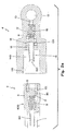
- Fig. 1A shows a schematic view in longitudinal section of an apparatus according to the invention, in a first embodiment thereof;
- Figs. 1B and 1C show enlarged details of Fig. 1A;
- Figs. 1D and 1E are a side view and a front view of the piston (9);
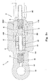
- Fig. 2A is a schematic view in longitudinal section of an apparatus according to the invention, in a further embodiment thereof;
- Figs. 2B and 2C show enlarged details of Fig. 2A.
- Reduced to its basic structure and reference being made to Figs. 1A-1C of the accompanying drawings, an apparatus according to the present invention comprises a hose (1), preferably flexible, able to be filled with fluid for hydraulic brakes and provided, in correspondence of both ends, with a hermetic-seal reversible coupling (2) to allow a tight-seal, reversible connection, on one side, with a body (4) connecting with a pump for hydraulic brakes and, on the other side, with a body (5) connecting with a caliper of a hydraulic brake.
- According to the example illustrated in Figs. 1A-1C of the accompanying drawings, the said couplings (2) located at both ends of hose (1) are identical with each other and, structurally identical to each other are also the said connectors (4) and (5). More precisely, each coupling (2) comprises a substantially cylindrical body (6) which has a drilled shank (60) to be fitted into the hose (1) and is located inside a ring nut (7) having internal threading and whose inner diameter (dg) is larger than the outer diameter (dc) of the cylindrical body (6), so that a cylindrical space (3) results between the body (6) and the ring nut (7). Inside said body (6) is a spring (8) disposed along the longitudinal axis of body (6) and to which a piston (9) is associated.
The body of the latter has a substantially spherical shape, with a rear appendix (92) on which an end portion of said spring (8) is fitted, and with four radial appendixes (91) which, in cooperation with the internal wall of said body (6), define four ports (90). - In practice, the said appendixes (91) of the piston (9) are orthogonal to the longitudinal axis of the cylinder (6), and the said ports (90) are parallel to said axis; the spring (8) results between the piston (9) and the base (61) of cylinder (6) from which the shank (60) extends to fit into the hose (1).
- Mounted in correspondence of the other base (62) of cylinder (6) is a collar (10) and, between the latter and the piston (9) there is interposed a multilobe O-ring (101). The said collar (10) and the said O-ring (101) are disposed coaxial to each other and inside the cylinder (6). The inner diameter of the O-ring (101) is smaller than that of the piston with spherical head (9), so that the same piston results suitable for closing the port thereof.
- In practice, the piston with spherical head (9) results between the spring (8) and the O-ring (101) which, in turn, results between the piston with spherical head (9) and the collar (10).
- Again with reference to the example shown in Figs. 1A-1E of the accompanying drawings, each of said connectors (4, 5) comprises a body (11) exhibiting an internal cavity which communicates, through a corresponding port (12, 13), with a pump or respectively with a caliper of the braking system.
The said body (11) has a front portion (14) with external threading on which a ring nut (7) of a coupling (2) is to be screwed and whose inner diameter (da) is equal to the internal diameter (dg) of the ring nut (7), so that the cavity (140) delimited by said portion (14) of body (11) will result suitable for receiving the portion of body (6) which results inside the ring nut (7). The length (Ia) of said portion (14) of body (11) is such that when screwing the ring nut (7) all the way in onto the threaded portion (14) of body (11), the front base (62) of body (6) belonging to the coupling (2) will result in abutment with an internal base (141) of the said cavity (140). - Positioned inside the said cavity (140) of body (6) is a hollow pin (15) associated with a spring (16) positioned between the rear base of the same pin (15) and the said port (12), that is, positioned within a second cavity (17) of body (11) and communicating with the first cavity (140) coaxially thereto.
The said pin (15) exhibits a front port (150) and a perimetral rear port (151), and can slide freely within the ports of a collar (18) and a multilobe O-ring (19) fitted on the same pin on the back of said internal base (141).
When the ring nut (7) is screwed all the way in onto the threaded portion (14) of body (11) - as illustrated in the bottom part of Fig. 1A and in Fig. 1C - both the piston with spherical head (9) and the hollow pin (15) move back, so that the port of the O-ring (101) and the port (151) of pin (15) become exposed. In relation to this, the hydraulic fluid is free to flow through the ports (12) and (13), cavity (17), port (151), port (150), ports (90) and shank (60), or vice versa. - When, instead, any of the couplings (2) is not connected, as above mentioned, to a connector (4, 5), no circulation of fluid can occur within the braking system which results sealed (as represented in the top part of Fig. 1A and in Fig. 1B).
- With reference to the example illustrated in Figs. 2A-2C of the accompanying drawings, the operational and constructional structure is substantially equal to that of the example shown in Figs. 1A-1E, except that the bodies (6) and (11) are not provided with threading and their mutual attachment is carried out by screw means acting through a hole (110) formed in the body (11) of connector (4, 5) and interesting the internal surface of the body (6) of each coupling (2) in correspondence of an annular groove (600).
- In the drawings of Figs. 2A-2C, the individual components are numbered like in Figs. 1A-1E, as they exhibit the same constructional structure and interact likewise.
Claims (6)
- Apparatus for connecting a pump and a caliper of a hydraulic brake, comprising a hose (1) within which a fluid for hydraulic brakes can flow, characterized in that the said hose (1) is provided, in correspondence of its ends, with a hermetic-seal reversible coupling (2) connectable to a connector (4, 5) of the pump and, respectively, of the caliper.
- Apparatus according to claim 1, characterized in that the said couplings (2) are identical to each other.
- Apparatus according to claim 1, characterized in that the said connectors (4; 5) are identical to each other.
- Apparatus according to claim 1, characterized in that each coupling (2) comprises a substantially cylindrical body (6) inside of which a piston (9) with spherical head is positioned, said piston being associated with an elastic member (8) and delimiting, in cooperation with the internal wall of said body (6), a plurality of axial ports (90) which are occluded when the elastic member (8) is extended, and are open when the elastic member (8) is compressed: the said ports (90) being in communication with said hose (1).
- Apparatus according to claims 1 and 4, characterized in that the said elastic member (8) is compressed when the said body (6) is connected with one of said connectors (4; 5).
- Apparatus according to claim 1, characterized in that each of said connectors (4; 5) comprises a body (11) exhibiting an internal cavity which communicates, through a corresponding port (12, 13), with a pump or respectively with a caliper, and inside which a hollow pin (15) is positioned, associated with an elastic member (16) and having perimetral ports (151) which are occluded when the elastic member (16) is extended and are open when the elastic member (16) is compressed: the said ports (151) being in communication with said hose (1).
Applications Claiming Priority (2)
| Application Number | Priority Date | Filing Date | Title |
|---|---|---|---|
| ITFI20030240 | 2003-09-12 | ||
| ITFI20030240 ITFI20030240A1 (en) | 2003-09-12 | 2003-09-12 | DEVICE FOR CONNECTING A CLAMP AND A HYDRAULIC BRAKE PUMP |
Publications (1)
| Publication Number | Publication Date |
|---|---|
| EP1514758A1 true EP1514758A1 (en) | 2005-03-16 |
Family
ID=34131185
Family Applications (1)
| Application Number | Title | Priority Date | Filing Date |
|---|---|---|---|
| EP20040425659 Withdrawn EP1514758A1 (en) | 2003-09-12 | 2004-09-01 | Apparatus for connection of a caliper and a pump for hydraulic brakes |
Country Status (3)
| Country | Link |
|---|---|
| US (1) | US20050056325A1 (en) |
| EP (1) | EP1514758A1 (en) |
| IT (1) | ITFI20030240A1 (en) |
Cited By (5)
| Publication number | Priority date | Publication date | Assignee | Title |
|---|---|---|---|---|
| EP2410197A1 (en) * | 2010-07-20 | 2012-01-25 | Hansen Industrial Transmissions | Brake system for an industrial gearbox |
| US9827968B2 (en) | 2015-01-12 | 2017-11-28 | Sram, Llc | Hydraulic bicycle system |
| WO2019081247A1 (en) * | 2017-10-25 | 2019-05-02 | Continental Teves Ag & Co. Ohg | FLUID CONTAINER WITH A LOCK VALVE |
| EP3756961A2 (en) | 2019-06-03 | 2020-12-30 | Gustav Magenwirth GmbH & Co. KG | Hydraulic line clutch, in particular for a hydraulic brake or clutch of handle bars-guided vehicles |
| WO2022137160A1 (en) * | 2020-12-22 | 2022-06-30 | Danfoss Power Solutions Ii Technology A/S | Secure brake fluid coupler |
Families Citing this family (2)
| Publication number | Priority date | Publication date | Assignee | Title |
|---|---|---|---|---|
| JP2008084809A (en) * | 2006-08-29 | 2008-04-10 | Yamaha Motor Co Ltd | Connection structure for piping for hydrogen supply |
| ITMI20130522A1 (en) * | 2013-04-05 | 2014-10-06 | Alfa Gomma S P A | HYDRAULIC OR HYDRAULIC QUICK COUPLING FOR FLUID IN PRESSURE |
Citations (6)
| Publication number | Priority date | Publication date | Assignee | Title |
|---|---|---|---|---|
| US2108714A (en) * | 1935-09-28 | 1938-02-15 | Hirsch Peter | Pipe coupling |
| DE953856C (en) * | 1953-07-01 | 1956-12-06 | Vogel Willy Fa | Plug-in and breakaway coupling for connecting lines, especially between vehicles |
| GB870822A (en) * | 1958-10-20 | 1961-06-21 | Spembly Ltd | Improvements in or relating to pipe line couplings |
| GB968522A (en) * | 1960-01-22 | 1964-09-02 | Plessey Co Ltd | Improvements in or relating to mounting arrangements including fluid couplings |
| JPH03153991A (en) * | 1989-11-10 | 1991-07-01 | Hitachi Cable Ltd | brake hose |
| JPH10220671A (en) * | 1997-02-07 | 1998-08-21 | Aisan Ind Co Ltd | Tube joint |
Family Cites Families (3)
| Publication number | Priority date | Publication date | Assignee | Title |
|---|---|---|---|---|
| US4607670A (en) * | 1983-11-28 | 1986-08-26 | Automotive Products Plc | Modular prefilled hydraulic control apparatus |
| US4624291A (en) * | 1984-04-30 | 1986-11-25 | Automotive Products Plc | Method of prefilling modular hydraulic control apparatus |
| FR2614371B1 (en) * | 1987-04-23 | 1993-04-09 | Bennes Marrel | CONTROL VALVE, ESPECIALLY FOR HYDRAULIC BRAKES OF A VEHICLE |
-
2003
- 2003-09-12 IT ITFI20030240 patent/ITFI20030240A1/en unknown
-
2004
- 2004-08-24 US US10/925,266 patent/US20050056325A1/en not_active Abandoned
- 2004-09-01 EP EP20040425659 patent/EP1514758A1/en not_active Withdrawn
Patent Citations (6)
| Publication number | Priority date | Publication date | Assignee | Title |
|---|---|---|---|---|
| US2108714A (en) * | 1935-09-28 | 1938-02-15 | Hirsch Peter | Pipe coupling |
| DE953856C (en) * | 1953-07-01 | 1956-12-06 | Vogel Willy Fa | Plug-in and breakaway coupling for connecting lines, especially between vehicles |
| GB870822A (en) * | 1958-10-20 | 1961-06-21 | Spembly Ltd | Improvements in or relating to pipe line couplings |
| GB968522A (en) * | 1960-01-22 | 1964-09-02 | Plessey Co Ltd | Improvements in or relating to mounting arrangements including fluid couplings |
| JPH03153991A (en) * | 1989-11-10 | 1991-07-01 | Hitachi Cable Ltd | brake hose |
| JPH10220671A (en) * | 1997-02-07 | 1998-08-21 | Aisan Ind Co Ltd | Tube joint |
Non-Patent Citations (3)
| Title |
|---|
| ALFRED TEVES GMBH: "Bremsen-Handbuch Berechnung, Funktion, Wartung und Instandsetzung", 1988, AUTOHAUS VERLAG GMBH, OTTOBRUNN, XP002308211 * |
| PATENT ABSTRACTS OF JAPAN vol. 015, no. 381 (M - 1162) 26 September 1991 (1991-09-26) * |
| PATENT ABSTRACTS OF JAPAN vol. 1998, no. 13 30 November 1998 (1998-11-30) * |
Cited By (14)
| Publication number | Priority date | Publication date | Assignee | Title |
|---|---|---|---|---|
| WO2012010586A1 (en) * | 2010-07-20 | 2012-01-26 | Hansen Industrial Transmissions | Brake system for an industrial gearbox |
| EP2410197A1 (en) * | 2010-07-20 | 2012-01-25 | Hansen Industrial Transmissions | Brake system for an industrial gearbox |
| US10407043B2 (en) | 2015-01-12 | 2019-09-10 | Sram, Llc | Hydraulic bicycle system |
| US9827968B2 (en) | 2015-01-12 | 2017-11-28 | Sram, Llc | Hydraulic bicycle system |
| US10086813B2 (en) | 2015-01-12 | 2018-10-02 | Sram, Llc | Hydraulic bicycle system |
| US11590948B2 (en) | 2017-10-25 | 2023-02-28 | Continental Teves Ag & Co. Ohg | Fluid reservoir with a stop valve |
| WO2019081247A1 (en) * | 2017-10-25 | 2019-05-02 | Continental Teves Ag & Co. Ohg | FLUID CONTAINER WITH A LOCK VALVE |
| EP3756961A2 (en) | 2019-06-03 | 2020-12-30 | Gustav Magenwirth GmbH & Co. KG | Hydraulic line clutch, in particular for a hydraulic brake or clutch of handle bars-guided vehicles |
| EP3756961A3 (en) * | 2019-06-03 | 2021-04-28 | Gustav Magenwirth GmbH & Co. KG | Hydraulic line clutch, in particular for a hydraulic brake or clutch of handle bars-guided vehicles |
| US11802644B2 (en) | 2019-06-03 | 2023-10-31 | Gustav Magenwirth Gmbh & Co. Kg | Hydraulic line coupling for a hydraulic brake or clutch of handlebar-operated vehicles and hydraulic brake of a handlebar-operated vehicle |
| EP4407224A2 (en) | 2019-06-03 | 2024-07-31 | Gustav Magenwirth GmbH & Co. KG | Hydraulic line clutch, in particular for a hydraulic brake or clutch of handle bars-guided vehicles |
| EP4407224A3 (en) * | 2019-06-03 | 2024-08-07 | Gustav Magenwirth GmbH & Co. KG | Hydraulic line clutch, in particular for a hydraulic brake or clutch of handle bars-guided vehicles |
| WO2022137160A1 (en) * | 2020-12-22 | 2022-06-30 | Danfoss Power Solutions Ii Technology A/S | Secure brake fluid coupler |
| US12624785B2 (en) | 2020-12-22 | 2026-05-12 | Danfoss A/S | Secure brake fluid coupler |
Also Published As
| Publication number | Publication date |
|---|---|
| ITFI20030240A1 (en) | 2005-03-13 |
| US20050056325A1 (en) | 2005-03-17 |
Similar Documents
| Publication | Publication Date | Title |
|---|---|---|
| US5385060A (en) | Device for the assembly or disassembly of probes in process pipes, tanks, etc. | |
| US9073516B2 (en) | Leveling jack for vehicle | |
| JP7075483B2 (en) | Hydraulic block for hydraulically assisted vehicle braking equipment | |
| BR112012027010B1 (en) | electro-hydraulic actuator group for automotive servo-assisted mechanical transmission and automotive servo-assisted mechanical transmission | |
| US20050056325A1 (en) | Apparatus for connection of a caliper and a pump for hydraulic brakes | |
| CN110576414A (en) | Sealing washer cup joints device and equipment thereof | |
| GB2088504A (en) | Flexible tubular joint | |
| US2557498A (en) | Swing joint | |
| CN201152330Y (en) | Allterrain vehicle hydraulic braking system three-piston brake cylinder | |
| EP2312169B1 (en) | Valve for controlling oil flow to a single acting cylinder | |
| AU2010246537B2 (en) | Leveling jack for vehicle | |
| CN208474224U (en) | A kind of hydraulic switch valve | |
| ES2927858T3 (en) | Braking system for a rail vehicle | |
| US6997523B1 (en) | Brake system | |
| US7543824B2 (en) | Hydraulic suspension unit | |
| JPH0248761B2 (en) | ||
| CN201082710Y (en) | Brake master cylinder | |
| CN100523522C (en) | Universal hydraulic coupler | |
| CN104763708B (en) | A kind of alpha contamination indicator | |
| CN114837590B (en) | Hydraulic pushing nipple of cable logging tractor | |
| CN207212812U (en) | integrated multi-cylinder synchronous hydraulic oil cylinder | |
| CN106956671B (en) | A kind of manual double spool brake valve | |
| CN110285310A (en) | A kind of hydraulic automatic switching control equipment | |
| CN224106503U (en) | A quick-change connector with integrated internal oil circuit | |
| CN213654783U (en) | Dry type flexible short joint |
Legal Events
| Date | Code | Title | Description |
|---|---|---|---|
| PUAI | Public reference made under article 153(3) epc to a published international application that has entered the european phase |
Free format text: ORIGINAL CODE: 0009012 |
|
| AK | Designated contracting states |
Kind code of ref document: A1 Designated state(s): AT BE BG CH CY CZ DE DK EE ES FI FR GB GR HU IE IT LI LU MC NL PL PT RO SE SI SK TR |
|
| AX | Request for extension of the european patent |
Extension state: AL HR LT LV MK |
|
| 17P | Request for examination filed |
Effective date: 20050325 |
|
| AKX | Designation fees paid |
Designated state(s): AT BE BG CH CY CZ DE DK EE ES FI FR GB GR HU IE IT LI LU MC NL PL PT RO SE SI SK TR |
|
| 17Q | First examination report despatched |
Effective date: 20060626 |
|
| STAA | Information on the status of an ep patent application or granted ep patent |
Free format text: STATUS: THE APPLICATION IS DEEMED TO BE WITHDRAWN |
|
| 18D | Application deemed to be withdrawn |
Effective date: 20061107 |