EP1514753A1 - Sensoranordnung zur Erfassung des Aggregatzustandes einer Flüssigkeit - Google Patents
Sensoranordnung zur Erfassung des Aggregatzustandes einer Flüssigkeit Download PDFInfo
- Publication number
- EP1514753A1 EP1514753A1 EP03020610A EP03020610A EP1514753A1 EP 1514753 A1 EP1514753 A1 EP 1514753A1 EP 03020610 A EP03020610 A EP 03020610A EP 03020610 A EP03020610 A EP 03020610A EP 1514753 A1 EP1514753 A1 EP 1514753A1
- Authority
- EP
- European Patent Office
- Prior art keywords
- liquid
- viscosity
- sensor arrangement
- movement
- detecting
- Prior art date
- Legal status (The legal status is an assumption and is not a legal conclusion. Google has not performed a legal analysis and makes no representation as to the accuracy of the status listed.)
- Granted
Links
Images

Classifications
-
- G—PHYSICS
- G01—MEASURING; TESTING
- G01N—INVESTIGATING OR ANALYSING MATERIALS BY DETERMINING THEIR CHEMICAL OR PHYSICAL PROPERTIES
- G01N25/00—Investigating or analyzing materials by the use of thermal means
- G01N25/02—Investigating or analyzing materials by the use of thermal means by investigating changes of state or changes of phase; by investigating sintering
- G01N25/04—Investigating or analyzing materials by the use of thermal means by investigating changes of state or changes of phase; by investigating sintering of melting point; of freezing point; of softening point
-
- B—PERFORMING OPERATIONS; TRANSPORTING
- B60—VEHICLES IN GENERAL
- B60S—SERVICING, CLEANING, REPAIRING, SUPPORTING, LIFTING, OR MANOEUVRING OF VEHICLES, NOT OTHERWISE PROVIDED FOR
- B60S1/00—Cleaning of vehicles
- B60S1/02—Cleaning windscreens, windows or optical devices
- B60S1/46—Cleaning windscreens, windows or optical devices using liquid; Windscreen washers
- B60S1/48—Liquid supply therefor
- B60S1/481—Liquid supply therefor the operation of at least part of the liquid supply being controlled by electric means
-
- B—PERFORMING OPERATIONS; TRANSPORTING
- B60—VEHICLES IN GENERAL
- B60S—SERVICING, CLEANING, REPAIRING, SUPPORTING, LIFTING, OR MANOEUVRING OF VEHICLES, NOT OTHERWISE PROVIDED FOR
- B60S1/00—Cleaning of vehicles
- B60S1/02—Cleaning windscreens, windows or optical devices
- B60S1/46—Cleaning windscreens, windows or optical devices using liquid; Windscreen washers
- B60S1/48—Liquid supply therefor
- B60S1/487—Liquid supply therefor the liquid being heated
- B60S1/488—Liquid supply therefor the liquid being heated electrically
-
- B—PERFORMING OPERATIONS; TRANSPORTING
- B60—VEHICLES IN GENERAL
- B60S—SERVICING, CLEANING, REPAIRING, SUPPORTING, LIFTING, OR MANOEUVRING OF VEHICLES, NOT OTHERWISE PROVIDED FOR
- B60S1/00—Cleaning of vehicles
- B60S1/02—Cleaning windscreens, windows or optical devices
- B60S1/46—Cleaning windscreens, windows or optical devices using liquid; Windscreen washers
- B60S1/48—Liquid supply therefor
- B60S1/50—Arrangement of reservoir
-
- G—PHYSICS
- G01—MEASURING; TESTING
- G01N—INVESTIGATING OR ANALYSING MATERIALS BY DETERMINING THEIR CHEMICAL OR PHYSICAL PROPERTIES
- G01N11/00—Investigating flow properties of materials, e.g. viscosity, plasticity; Analysing materials by determining flow properties
- G01N11/10—Investigating flow properties of materials, e.g. viscosity, plasticity; Analysing materials by determining flow properties by moving a body within the material
Definitions
- the invention relates to an arrangement for detecting a state variable of a liquid in a container, such as the temperature or state of matter of the liquid, in particular of water or an aqueous solution in a container in vehicles.
- a sensor detecting the state variable of the liquid gives a message signal which causes the switching on of a heater to heat in to bring in the container.
- the solidification temperature of the washing liquid depends on the mixing ratio Antifreeze off. Furthermore, the washing liquid at different points in the Passenger cars will be affected by the cooling to varying degrees, leaving parts in the plant already frozen, while others are still liquid.
- Another starting point of the invention are additional containers for water or for aqueous Solutions that control the combustion process and / or the effectiveness of a catalyst support.
- the reduction of nitrogen oxide by means of catalytic exhaust aftertreatment is particularly effective according to the SCR procedure.
- This is an aqueous solution of Ammonia, better still of urea directly into the catalyst (not in the combustion chamber) injected.
- 32% urea solutions are used in SCR systems used in diesel engines.
- This solution has a freezing point of -11 ° C. Therefore, there must be devices that prevent freezing (Heaters) and / or devices that monitor the temperature
- Vehicles must therefore carry an additional tank, which in a truck up to 50 liters Can have volume.
- the known arrangements have the disadvantage that the exact solidification temperature may vary depending on the amount of admixture to the water content, the heater but still set to a specific temperature switching point. Either starts the heating, although no liquid has solidified, or sets the heating not a, because the setting of the temperature-switching point does not match the concentration of antifreeze is tuned. Then solidified scrubbing liquid would not be heated become.
- the invention has for its object to propose an arrangement which the determination of the solidification or the beginning change of the state of aggregation without the aid of a thermal sensor allows.
- the gist of the invention is first a viscosity sensor for the determination of solidification or the beginning of solidification.
- the viscosity-detecting message signal activated the heater, when the determined viscosity of the viscosity of the fluid Condition of the liquid deviates.
- the viscosity of a suitable as a washing liquid Liquid changes in the temperature range between +10 ° C and its solidification point in the negative Celsius range only little. After the onset of ice formation changes the viscosity clearly, so that the viscosity is a very suitable state variable, the Beginning of solidification or to detect the solidified state itself.
- the viscosity sensor is preferably designed as a mechanical sensor.
- a movement element may be displaceable in a linear or rotational movement. It is preferably movable by electromechanical means.
- the size of the motion element should be such that there is sufficient flow resistance in the fluid experiences. According to this measurement principle is proposed, a movable To introduce element into the liquid, which electromechanically acted upon is, and that a motion sensor is present, the position or the movement of the movement element.
- the movement of the moving element in the liquid occurs when ice particles appear delayed.
- the processing of the signal of the motion sensor is predetermined such that a distinction is made between unhindered and delayed movement.
- the delay dependent signaling signal activates the heater when the determined viscosity of the viscosity of the liquid deviates in the fully fluid state.
- the heater takes the heating and thawing of the solidified liquid before, whereby the heating power from 0 to 100% are made changeable can, depending on the size of the motion signal.
- the movement element can be arranged to be rotatable about an axis.
- Here would be for example to provide an impeller which is drivable by an electric motor. Of the Electric motor is switched so that it generates a fixed speed. The power consumption to generate the specified speed is measured with a Wattmeter and depends on the viscosity of the liquid.
- the movement element can also be linearly movable in a linear guide, wherein analog detection elements are used for the determination of the viscosity.
- the movement can also be done by activating an electromagnet, which comes with a cooperates in the moving element arranged permanent magnet.
- the Time delay between activation of the electromagnet and start of movement is taken as a measure of the existing viscosity.
- the motion sensor may consist of a reed contact, that of one in the motion element arranged and the reed contact associated permanent magnet is addressed.
- Another, particularly preferred embodiment of this Art is shown in detail in the description of the figure.
- the moving element attached to a rocker whose arms each carry a permanent magnet, wherein the first arm in the area of an electromagnet and the second arm in the area of a Reed switch is arranged.
- a second embodiment of the invention is claimed, with the specific Volume, or the density of the liquid is monitored. It includes a fixed volume the liquid receiving chamber to which a pressure measuring arrangement arranged is, which emits a message signal depending on the measured pressure, wherein the message signal of the pressure measuring arrangement is processed in an electronics such that the heat to be introduced by the heater depends on the deviation of the measured Pressure from the pressure in the fully fluid state Liquid is measured.
- the liquid enters the closed chamber fixed volume. Depending on the temperature, on the composition and the state of aggregation changes the density, or the specific volume, which is taken as a measured variable.
- the chamber can be flowed through for flushing with liquid.
- the inflow and outflow channels can be closed with a valve be.
- the occurring capillary forces are sufficient to a defined Keep fluid volume inside the chamber.
- a wall of the chamber is designed as a pressure membrane, which in Actual connection with a pressure-receiving element is.
- a pressure membrane which in Actual connection with a pressure-receiving element is.
- a piezoelectric element can be used.
- a mechanical transducer such.
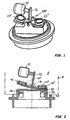
- Figures 1 and 2 show the arrangement 100, the essential parts of a rocker 12th and a movement element 10 designed as a floating or buoyant body, which is attached to an approximately vertically upstanding web of the rocker 12.
- This arrangement is located in an indicated container 8 for a washing liquid 5.
- the assembly could be located at the bottom of the container.
- a groove 40 indicated that for receiving a cylindrical wall a container is suitable.
- the container can be sealed liquid-tight in the groove be.
- Other arbitrary arrangements are of course possible. For example, too the arrangement of FIG. 2 are placed upside down from above in the container. The buoyancy force directed the other way round must be in the training and the angle design the rocker be considered. The expert can easily after the Description of the invention corresponding modifications of the construction while maintaining of the principle.
- the rocker has two at an obtuse angle to each other standing arms 16 ', 16 ", each one Permanent magnet 20 ', 20 "wear
- the neutral position of the rocker in the liquid is balanced so that the float is raised and the left arm 16 'from Permanent magnet 20 'away.
- the left arm 16 ' is in the region of an electromagnet 34 arranged.
- In the neutral position is the second, right permanent magnet 20 "near a reed contact 32.
- Reference numeral 30 is a circuit board indicated that both the electromagnet 34 and the reed contact and possibly other electrical components, lines and contacts or a carries integrated electronics.
- the rocker When current flows through the coil of the electromagnet 34, the rocker is about the axis 14th turning left to move. The right arm 16 "away from the reed contact 32.
- An electronics not shown, the time delay between current flow by the electromagnet 34 and the opening or closing of the reed contact detected. As a result, the message signal comes off depending on the length of the Time delay, which is the greater, the stronger the movement of the float 10 is hindered by ice in the washing liquid 5.
- the scale is a time delay, which is measurable in a completely liquid fluid state in a washing liquid.
- the (not shown) heater in the Washing liquid switched on when the message signal a different, namely larger Time delay reports.
- the time delay is a measure of the viscosity.
- the Heating capacity can be adjusted accordingly variable, so that the dosage of introduced heat energy depending on the viscosity is feasible.
- Fig. 3 shows schematically the other arrangement 200 in section.
- She can, like the first Arrangement in the corresponding additional container of the motor vehicle or by communicating Tubes communicate with the liquid in the container.
- the core of Arrangement is a liquid 5 'receiving chamber 52.
- the chamber is cone-shaped formed and in a stable, preferably made of plastic housing 50 housed.
- a pressure membrane 54 In the lower area is a pressure membrane 54, at her is the consisting of a piezoelectric element 62 pressure measuring arrangement, which in a mounting flange 61 is included, arranged.
- a pestle which is connected to a switch, be provided as a transducer.
- the pressure membrane 54 is on the side facing away from the liquid Membrane side provided a membrane expansion volume 55.
- the composition and the state of matter changes the density, or the specific volume of the liquid 5 ', the change of the Physical state here particularly interested.
- the change of the state quantity becomes taken at the contact point 56 to the piezoelectric element as pressure.
- the piezoelectric element inputs via an electrical contact 64 Signal from.
- the message signal is processed in a manner not shown electronics, that the heat to be introduced by the heater from the deviation the measured pressure of the pressure in the fully fluid state Liquid is measured.
- the chamber 52 has inlet and outlet channels (51 ', 51 "), each with a valve (53', 53") are closable. However, the inflow and outflow channels 51 ', 51 "can also be unlocked remain, because due to the capillary forces normally a sufficiently defined Liquid volume is held in the chamber 52. If necessary, the chamber 52 are flushed with liquid 5 '.
Landscapes
- Engineering & Computer Science (AREA)
- Mechanical Engineering (AREA)
- Water Supply & Treatment (AREA)
- General Health & Medical Sciences (AREA)
- Analytical Chemistry (AREA)
- Biochemistry (AREA)
- Physics & Mathematics (AREA)
- General Physics & Mathematics (AREA)
- Immunology (AREA)
- Pathology (AREA)
- Chemical & Material Sciences (AREA)
- Life Sciences & Earth Sciences (AREA)
- Health & Medical Sciences (AREA)
- Investigating Or Analyzing Materials Using Thermal Means (AREA)
Abstract
Description
- FIG. 1
- eine perspektivische Darstellung einer Anordnung mit rotativem Bewegungselement,
- FIG. 2
- eine Schnittdarstellung der ersten Anordnung und
- FIG. 3
- eine Schnittdarstellung einer Druckmessanordnung.
- 100
- erste Anordnung
- 5, 5'
- Flüssigkeit
- 8
- Behälter
- 10
- Bewegungselement
- 12
- Wippe
- 14
- Achse
- 16', 16"
- Arme
- 20', 20"
- Permanentmagnete
- 30
- Platine
- 32
- Bewegungssensor = Reed-Kontakt
- 34
- Elektromagnet (Spule)
- 40
- Nut
- 200
- zweite Anordnung
- 50
- Isolierkörper
- 51', 51"
- Zugangsröhrchen
- 52
- Kammer
- 53', 53"
- Ventile
- 54
- Membran
- 55
- Membranausdehnungsvolumen
- 56
- Berührungsfläche
- 61
- Befestigungsflansch für Stößel mit Schalter oder Piezoelement
- 62
- Piezoelement
- 64
- elektrischer Kontakt
Claims (12)
- Sensoranordnung zur Erfassung einer Zustandsgröße einer Flüssigkeit in einem Behälter, insbesondere von Wasser oder einer wässrigen Lösung in einem Behälter in Fahrzeugen, wobei ein die Zustandsgröße der Flüssigkeit (5, 5') erfassender Aufnehmer ein Meldesignal abgibt, welches eine Heizeinrichtung veranlasst, Wärme in den Behälter (8) einzubringen,
dadurch gekennzeichnet, dass ein die Viskosität oder das spezifische Volumen der Flüssigkeit (5, 5') erfassender Aufnehmer (10,12,32,62) eingesetzt wird, dessen Meldesignal die Heizeinrichtung aktiviert, wenn die ermittelte Viskosität von der Viskosität des fluiden Zustandes der Flüssigkeit (5, 5') oder das spezifische Volumen vom spezifischen Volumen des fluiden Zustandes der Flüssigkeit (5, 5') abweicht. - Sensoranordnung zur Erfassung der Viskosität nach Anspruch 1, dadurch gekennzeichnet, dass die Anordnung aus einem in Bewegung versetzbaren Element (10,12) und einem Bewegungssensor (32) besteht, der die Bewegung des Bewegungselements (10,12) erfasst, und abhängig von der Bewegung ein Meldesignal abgibt, wobei das Meldesignal des Aufnehmers (32) in einer Elektronik derart verarbeitet wird, dass die von der Heizeinrichtung einzubringende Wärme von der Abweichung der Bewegung des Bewegungselements (10,12) von seiner Bewegung in der vollständig im fluiden Zustand befindlichen Flüssigkeit bemessen wird.
- Sensoranordnung zur Erfassung der Viskosität nach einem der vorhergehenden Ansprüche, dadurch gekennzeichnet, dass das Bewegungselement (10,12) in lineare oder in rotative Bewegung versetzbar ist.
- Sensoranordnung zur Erfassung der Viskosität nach einem der vorhergehenden Ansprüche, dadurch gekennzeichnet, dass das Bewegungselement (10,12) auf elektromechanischem Wege bewegbar ist.
- Sensoranordnung nach Anspruch 3 oder 4, dadurch gekennzeichnet, dass das Bewegungselement (10,12) nach dem Prinzip des Elektromotors bewegt und die Leistungsaufnahme des Elektromotors als Maß für die vorhandene Viskosität genommen wird.
- Sensoranordnung nach einem der Ansprüche 3 oder 4, dadurch gekennzeichnet, dass die Bewegung durch Aktivierung eines Elektromagneten (34) erfolgt, der mit einem im Bewegungselement (10,12) angeordneten Permanentmagneten (20') zusammen wirkt und die Zeitverzögerung zwischen Aktivierung des Elektromagneten (34) und Beginn der Bewegung als Maß für die vorhandene Viskosität genommen wird.
- Sensoranordnung zur Erfassung der Viskosität nach einem der vorhergehenden Ansprüche, dadurch gekennzeichnet, dass der Bewegungssensor (32) aus einem Reed-Kontakt (32) besteht, der von einem im Bewegungselement (10,14) angeordneten Permanentmagneten (20) angesprochen wird.
- Sensoranordnung zur Erfassung der Viskosität nach einem der Ansprüche 6 oder 7, dadurch gekennzeichnet, dass das Bewegungselement (10) an einer Wippe (12) befestigt ist, deren Arme (16'; 16") je einen Permanentmagneten (20',20") tragen, wobei ein erster Arm (16') im Bereich eines Elektromagneten (34) und ein zweiter Arm (16") im Bereich eines Reed-Kontakts (32) angeordnet ist.
- Sensoranordnung zur Erfassung des spezifischen Volumens nach Anspruch 1, dadurch gekennzeichnet, dass der Aufnehmer (200) aus einer ein festes Volumen der Flüssigkeit (5') aufnehmenden Kammer (52) besteht, an der eine Druckmessanordnung (54,62) angeordnet ist, welche in Abhängigkeit vom gemessenen Druck ein Meldesignal abgibt, wobei das Meldesignal in einer Elektronik derart verarbeitet wird, dass die von der Heizeinrichtung einzubringende Wärme von der Abweichung des gemessenen Drucks von dem Druck in der vollständig im fluiden Zustand befindlichen Flüssigkeit (5') bemessen wird.
- Sensoranordnung nach Anspruch 9, dadurch gekennzeichnet, dass die Kammer (52) zum Durchspülen mit Flüssigkeit (5') durchströmbar ist.
- Sensoranordnung nach Anspruch 9 oder 10, dadurch gekennzeichnet, dass eine Wand der Kammer (52) als Druckmembran (54) ausgebildet ist, die in Wirkverbindung (56) mit einem druckaufnehmenden Element (62) steht.
- Sensoranordnung nach Anspruch 11, dadurch gekennzeichnet, dass das druckaufnehmende Element (62) ein Piezoelement ist.
Priority Applications (2)
| Application Number | Priority Date | Filing Date | Title |
|---|---|---|---|
| DE50302322T DE50302322D1 (de) | 2003-09-10 | 2003-09-10 | Sensoranordnung zur Erfassung des Aggregatzustandes einer Flüssigkeit |
| EP20030020610 EP1514753B1 (de) | 2003-09-10 | 2003-09-10 | Sensoranordnung zur Erfassung des Aggregatzustandes einer Flüssigkeit |
Applications Claiming Priority (1)
| Application Number | Priority Date | Filing Date | Title |
|---|---|---|---|
| EP20030020610 EP1514753B1 (de) | 2003-09-10 | 2003-09-10 | Sensoranordnung zur Erfassung des Aggregatzustandes einer Flüssigkeit |
Publications (2)
| Publication Number | Publication Date |
|---|---|
| EP1514753A1 true EP1514753A1 (de) | 2005-03-16 |
| EP1514753B1 EP1514753B1 (de) | 2006-02-01 |
Family
ID=34130181
Family Applications (1)
| Application Number | Title | Priority Date | Filing Date |
|---|---|---|---|
| EP20030020610 Expired - Lifetime EP1514753B1 (de) | 2003-09-10 | 2003-09-10 | Sensoranordnung zur Erfassung des Aggregatzustandes einer Flüssigkeit |
Country Status (2)
| Country | Link |
|---|---|
| EP (1) | EP1514753B1 (de) |
| DE (1) | DE50302322D1 (de) |
Cited By (1)
| Publication number | Priority date | Publication date | Assignee | Title |
|---|---|---|---|---|
| FR3040948A1 (fr) * | 2015-09-15 | 2017-03-17 | Valeo Systemes Dessuyage | Procede et dispositif de degivrage d’une vitre de vehicule |
Citations (5)
| Publication number | Priority date | Publication date | Assignee | Title |
|---|---|---|---|---|
| US4252097A (en) * | 1978-06-26 | 1981-02-24 | The Bendix Corporation | Viscosity compensated fuel injection system |
| EP0116419A2 (de) * | 1983-01-26 | 1984-08-22 | Wallis, Brian | Einrichtung zur Aufheizung von Dieselkraftstoff |
| DE4426179A1 (de) | 1994-07-23 | 1996-01-25 | Vdo Schindling | Vorrichtung zum Beheizen von Reinigungsflüssigkeit für eine Scheiben-Waschanlage |
| US5706780A (en) * | 1995-10-31 | 1998-01-13 | Nissan Motor Co., Ltd. | Diesel engine fuel property determining device and controller |
| US6266842B1 (en) * | 1998-05-06 | 2001-07-31 | MüLLER HERMANN-FRANK | Windshield cleaning device with liquid collection |
-
2003
- 2003-09-10 EP EP20030020610 patent/EP1514753B1/de not_active Expired - Lifetime
- 2003-09-10 DE DE50302322T patent/DE50302322D1/de not_active Expired - Lifetime
Patent Citations (5)
| Publication number | Priority date | Publication date | Assignee | Title |
|---|---|---|---|---|
| US4252097A (en) * | 1978-06-26 | 1981-02-24 | The Bendix Corporation | Viscosity compensated fuel injection system |
| EP0116419A2 (de) * | 1983-01-26 | 1984-08-22 | Wallis, Brian | Einrichtung zur Aufheizung von Dieselkraftstoff |
| DE4426179A1 (de) | 1994-07-23 | 1996-01-25 | Vdo Schindling | Vorrichtung zum Beheizen von Reinigungsflüssigkeit für eine Scheiben-Waschanlage |
| US5706780A (en) * | 1995-10-31 | 1998-01-13 | Nissan Motor Co., Ltd. | Diesel engine fuel property determining device and controller |
| US6266842B1 (en) * | 1998-05-06 | 2001-07-31 | MüLLER HERMANN-FRANK | Windshield cleaning device with liquid collection |
Cited By (2)
| Publication number | Priority date | Publication date | Assignee | Title |
|---|---|---|---|---|
| FR3040948A1 (fr) * | 2015-09-15 | 2017-03-17 | Valeo Systemes Dessuyage | Procede et dispositif de degivrage d’une vitre de vehicule |
| EP3144190A1 (de) * | 2015-09-15 | 2017-03-22 | Valeo Systèmes d'Essuyage | Verfahren und vorrichtung zur enteisung einer fahrzeugscheibe |
Also Published As
| Publication number | Publication date |
|---|---|
| EP1514753B1 (de) | 2006-02-01 |
| DE50302322D1 (de) | 2006-04-13 |
Similar Documents
| Publication | Publication Date | Title |
|---|---|---|
| EP1252492B1 (de) | Drucksensor zum erfassen des druckes einer flüssigkeit | |
| WO2002025075A1 (de) | Vorrichtung zur dosierung eines reduktionsmittels | |
| EP2215435B1 (de) | Sensoranordnung zur bestimmung eines tankfüllstands | |
| DE112007002598T5 (de) | Behandlungssystem für abgetrenntes Wasser für Dieselmotor | |
| WO2011032709A1 (de) | Heizungsanordnung | |
| EP2863215B1 (de) | Sensorvorrichtung zur Erfassung von Eigenschaften fluider Medien | |
| DE102013001237A1 (de) | Filtervorrichtung für einen Flüssigkeitsbehälter, insbesondere für wässrige Harnstofflösung | |
| EP2145083B1 (de) | Scr-vorrichtung zur selektiven katalytischen reduktion des abgases einer brennkraftmaschine | |
| WO2013030066A2 (de) | Vorrichtung zur bereitstellung von flüssigem reduktionsmittel | |
| DE102009038744A1 (de) | Anordnung zur Füllstandsmessung | |
| EP1514753B1 (de) | Sensoranordnung zur Erfassung des Aggregatzustandes einer Flüssigkeit | |
| CH698633B1 (de) | Vorrichtung zur Durchflussmessung. | |
| DE19920370C1 (de) | Verfahren zur Bestimmung der Gefriertemperatur einer Flüssigkeit und eine hierfür bestimmte Vorrichtung | |
| EP1626936B1 (de) | Vorrichtung für die wasserenthärtung | |
| EP2215436B1 (de) | Sensoranordnung zur bestimmung eines tankfüllstands und tank mit sensoranordnung | |
| DE102008042954A1 (de) | Dosiersystem für ein flüssiges Medium, insbesondere Harnstoff-Wasser-Lösung | |
| DE102017218755A1 (de) | Messvorrichtung zum Bestimmen der Qualität eines flüssigen Reduktionsmittels | |
| DE102019215060B3 (de) | Flüssigkeitsfilter und Tankfiltersystem mit einem Flüssigkeitsfilter | |
| DE202014103537U1 (de) | Sensorvorrichtung zur Erfassung von Eigenschaften fluider Medien | |
| DE102021106331A1 (de) | Filtereinsatz zum Einsetzen in ein Filtergehäuse eines Fluidfilters | |
| DE102023203819B4 (de) | Versorgungsmodul für ein Reinigungssystem | |
| DE102016110637B4 (de) | Drucksensorvorrichtung und Formelement für die Drucksensorvorrichtung | |
| EP3755976B1 (de) | Schallführungseinheit und tank zur speicherung fluiden reduktionsmittels | |
| DE102017218756A1 (de) | Messvorrichtung zum Bestimmen der Qualität eines flüssigen Reduktionsmittels | |
| DE102019125072B4 (de) | Kältekreislauf und Fahrzeug |
Legal Events
| Date | Code | Title | Description |
|---|---|---|---|
| PUAI | Public reference made under article 153(3) epc to a published international application that has entered the european phase |
Free format text: ORIGINAL CODE: 0009012 |
|
| 17P | Request for examination filed |
Effective date: 20040304 |
|
| AK | Designated contracting states |
Kind code of ref document: A1 Designated state(s): AT BE BG CH CY CZ DE DK EE ES FI FR GB GR HU IE IT LI LU MC NL PT RO SE SI SK TR |
|
| AX | Request for extension of the european patent |
Extension state: AL LT LV MK |
|
| GRAP | Despatch of communication of intention to grant a patent |
Free format text: ORIGINAL CODE: EPIDOSNIGR1 |
|
| RAP1 | Party data changed (applicant data changed or rights of an application transferred) |
Owner name: DBK DAVID + BAADER GMBH |
|
| GRAS | Grant fee paid |
Free format text: ORIGINAL CODE: EPIDOSNIGR3 |
|
| RBV | Designated contracting states (corrected) |
Designated state(s): DE |
|
| AKX | Designation fees paid |
Designated state(s): DE |
|
| GRAA | (expected) grant |
Free format text: ORIGINAL CODE: 0009210 |
|
| AK | Designated contracting states |
Kind code of ref document: B1 Designated state(s): DE |
|
| REF | Corresponds to: |
Ref document number: 50302322 Country of ref document: DE Date of ref document: 20060413 Kind code of ref document: P |
|
| PLBE | No opposition filed within time limit |
Free format text: ORIGINAL CODE: 0009261 |
|
| STAA | Information on the status of an ep patent application or granted ep patent |
Free format text: STATUS: NO OPPOSITION FILED WITHIN TIME LIMIT |
|
| 26N | No opposition filed |
Effective date: 20061103 |
|
| PGFP | Annual fee paid to national office [announced via postgrant information from national office to epo] |
Ref country code: DE Payment date: 20100909 Year of fee payment: 8 |
|
| PG25 | Lapsed in a contracting state [announced via postgrant information from national office to epo] |
Ref country code: DE Free format text: LAPSE BECAUSE OF NON-PAYMENT OF DUE FEES Effective date: 20130403 |
|
| REG | Reference to a national code |
Ref country code: DE Ref legal event code: R119 Ref document number: 50302322 Country of ref document: DE Effective date: 20130403 |